System For Inducing Desirable Temperature Effects On Body Tissue
Stone; Corbett W. ; et al.
U.S. patent application number 16/524359 was filed with the patent office on 2020-01-02 for system for inducing desirable temperature effects on body tissue. The applicant listed for this patent is Boston Scientific Scimed, Inc.. Invention is credited to Arthur G. Blanck, Len Briggs, Rolfe Tyson Gustus, Michael F. Hoey, Mike Perry, Corbett W. Stone.
| Application Number | 20200000519 16/524359 |
| Document ID | / |
| Family ID | 39314847 |
| Filed Date | 2020-01-02 |


View All Diagrams
| United States Patent Application | 20200000519 |
| Kind Code | A1 |
| Stone; Corbett W. ; et al. | January 2, 2020 |
SYSTEM FOR INDUCING DESIRABLE TEMPERATURE EFFECTS ON BODY TISSUE
Abstract
A catheter and catheter system may be used to treat disease tissue by gentle heating in combination with gentle or standard dilation. An elongate flexible catheter body with a radially expandable balloon having a plurality of electrodes engage tissue including diseased tissue when the structure expands.
| Inventors: | Stone; Corbett W.; (San Diego, CA) ; Hoey; Michael F.; (Shoreview, MA) ; Blanck; Arthur G.; (Ramona, CA) ; Briggs; Len; (Carlsbad, CA) ; Perry; Mike; (Los Altos, CA) ; Gustus; Rolfe Tyson; (San Diego, CA) | ||||||||||
| Applicant: |
|
||||||||||
|---|---|---|---|---|---|---|---|---|---|---|---|
| Family ID: | 39314847 | ||||||||||
| Appl. No.: | 16/524359 | ||||||||||
| Filed: | July 29, 2019 |
Related U.S. Patent Documents
| Application Number | Filing Date | Patent Number | ||
|---|---|---|---|---|
| 13385555 | Feb 24, 2012 | 10413356 | ||
| 16524359 | ||||
| 11975383 | Oct 18, 2007 | 9125667 | ||
| 13385555 | ||||
| 60976733 | Oct 1, 2007 | |||
| 60921973 | Apr 4, 2007 | |||
| 60852787 | Oct 18, 2006 | |||
| Current U.S. Class: | 1/1 |
| Current CPC Class: | A61B 2018/00702 20130101; A61B 2018/00214 20130101; A61F 2007/126 20130101; A61B 18/1492 20130101; A61B 2018/00875 20130101; A61F 7/123 20130101; A61F 7/12 20130101; A61B 2018/0022 20130101 |
| International Class: | A61B 18/14 20060101 A61B018/14; A61F 7/12 20060101 A61F007/12 |
Claims
1. A system, comprising: a catheter body having a proximal end and a distal end with an axis therebetween; a radially expandable member having a low profile insertion configuration and a larger profile configuration; and a plurality of electrode pairs included on a plurality of flexible circuits, the flexible circuits distributed about an outer surface of the expandable member, so as to define a plurality of remodeling zones extending circumferentially about a wall of a body lumen when the expandable member is in the larger profile configuration; and wherein the plurality of electrode pairs is configured to transmit a tissue remodeling energy to each of the plurality of remodeling zones such that the tissue remodeling energy transmitted to remodeling zones including both a target tissue and a collateral tissue heats the target tissue sufficiently to efficaciously alter the target tissue without causing thermal damage to the collateral tissue.
2. The system of claim 1, wherein each of the flexible circuits includes an associated bipolar electrode pair.
3. The system of claim 2, wherein the electrodes of each bipolar electrode pair are disposed on its associated flexible circuit so as to have a predetermined bipolar pair separation distance therebetween when the expandable member is in the larger profile configuration.
4. The system of claim 2, wherein the bipolar electrode pairs are configured to be energized with RF energy, and wherein the electrodes of the electrode pairs are circumferentially separated.
5. The system of claim 4, wherein a circumferential distance between the electrodes of the electrode pairs is within a range from about 0.25 to 2.5 mm.
6. The system of claim 4, wherein a spacing between the electrodes of the bipolar electrode pairs is such that the remodeling zones substantially circumscribe the circumference of the balloon.
7. The system of claim 1, wherein the electrodes are configured so that the remodeling energy is applied at a frequency at which the target tissue is more conductive than the collateral tissue.
8. The system of claim 1, further comprising: a controller electrically coupling a power source to the plurality of electrode pairs for heating each of the remodeling zones with the remodeling energy so that a temperature of the target tissue ranges from about 50.degree. C. to about 90.degree. C. while a temperature of the collateral tissue is limited to less than about 50.degree. C.-65.degree. C.
9. The system of claim 8, wherein the power source comprises an RF generator and the controller is configured to selectively direct RF energy to the plurality of electrode pairs.
10. The system of claim 8, wherein the controller is configured to use temperature information from the target tissue as feedback for delivering remodeling energy to the plurality of electrode pairs.
11. The system of claim 8, wherein the controller is configured to energize the plurality of electrode pairs according to a duty cycle.
12. A system, comprising: a catheter body having a proximal end and a distal end with an axis therebetween; a balloon supported by the distal end of the catheter body, the balloon having a low profile insertion configuration and a larger profile configuration; a plurality of flex circuits defining a plurality of remodeling zones that extend about a circumference of a body lumen when the balloon is in the larger profile configuration, each flex circuit comprising a pair of electrodes mounted thereto, the flexible circuits being sufficiently flexible to allow folding and inflation of the balloon; and a power source configured to electrically couple with the electrodes of the flex circuits, and to transmit a tissue remodeling energy between the electrodes of the pairs, wherein the power source is further configured to transmit the tissue remodeling energy to each of the plurality of remodeling zones such that the tissue remodeling energy transmitted to remodeling zones including both a target tissue and a collateral tissue heats the target tissue sufficiently to efficaciously alter the target tissue without causing thermal damage to the collateral tissue.
13. The system of claim 12, wherein the power source is configured to energize the pairs of electrodes with about 0.25 to 20 Watts average power for a duration between 1 to 180 seconds.
14. The system of claim 12, wherein the power source s configured to energize the pairs of electrodes so as to deliver 8 to 45 Joules of energy in a treatment.
15. The system of claim 12, wherein the system is configured to affect controlled delivery of the tissue remodeling energy using a characteristic of the target tissue measured with one or more of the pairs of electrodes.
16. The system of claim 15, wherein the characteristic comprises a load impedance.
17. A method for treating target tissue disposed about a body lumen of a patient, comprising: positioning a radially expandable member, having a plurality of flexible circuits disposed on an outer surface thereof and supported by a distal end of a catheter body, within the body lumen adjacent the target tissue to be treated, the expandable member having a low profile insertion configuration and a larger profile configuration and each flexible circuit comprising a pair of electrodes that collectively define a plurality of electrodes; expanding the expandable member to the larger profile configuration so as to engage the plurality of electrodes against the body lumen, the pairs of electrodes defining a plurality of remodeling zones in the target tissue that extend about a circumference of the body lumen; energizing the plurality of electrodes to transmit a remodeling energy to each of the plurality of remodeling zones; and treating the target tissue and collateral tissue with the remodeling energy in the plurality of remodeling zones including the target tissue so as to efficaciously alter the target tissue while inhibiting damage to the collateral tissue.
18. The method of claim 17, wherein energy is controlled by selectively firing the pairs of electrodes of the plurality of electrodes.
19. The method of claim 17, wherein the pairs of electrodes are selectively fired according to a duty cycle.
20. The method of claim 17, wherein the plurality of remodeling zones are circumferentially and axially offset.
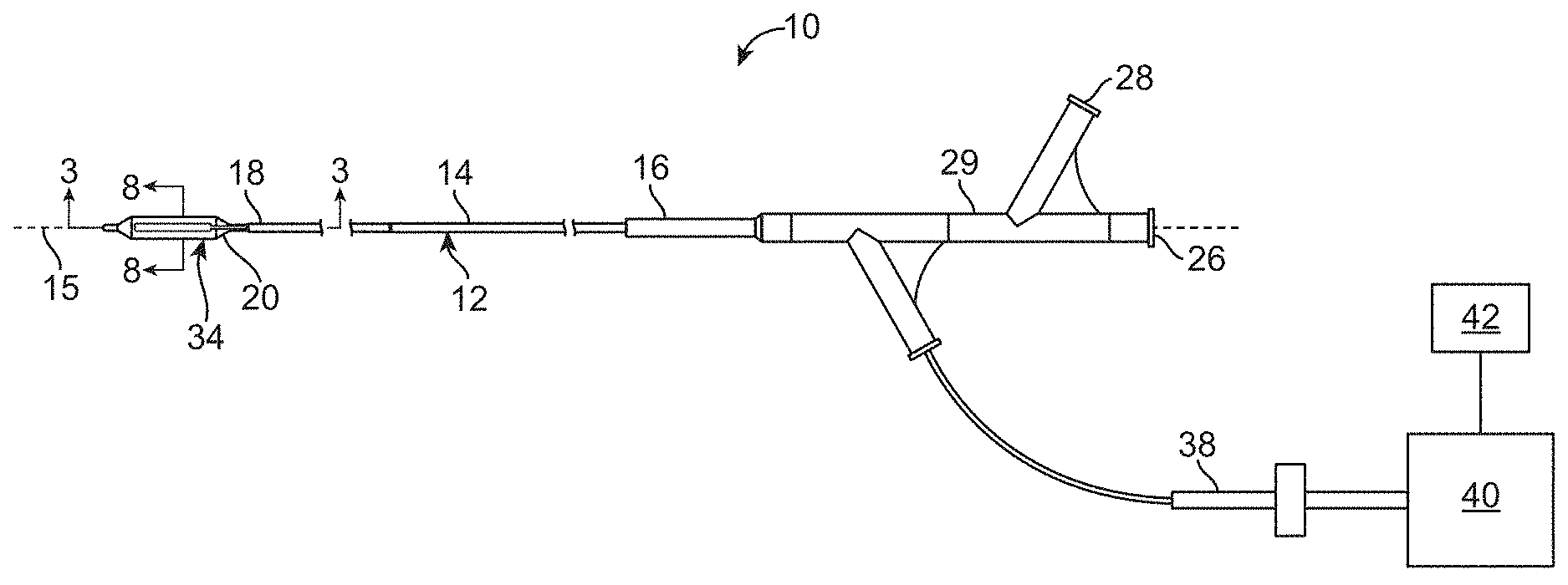
Description
CROSS-REFERENCES TO RELATED APPLICATIONS
[0001] This application is a continuation of U.S. patent application Ser. No. 13/385,555, filed Feb. 24, 2012, which is a continuation of and claims the benefit of U.S. patent application Ser. No. 11/975,383 filed Oct. 18, 2007, which claims the benefit under 35 USC 119(e) of U.S. Provisional Application No. 60/852,787, filed on Oct. 18, 2006, and entitled "Tuned RF Energy And Electrical Tissue Characterization For Selective Treatment Of Target Tissues"; U.S. Provisional Application No. 60/921,973, filed on Apr. 4, 2007, and entitled "Tuned RF Energy And Electrical Tissue Characterization For Selective Treatment Of Target Tissues", and U.S. Provisional Application No. 60/976,733, filed on Oct. 1, 2007, entitled "System for Inducing Desirable Temperature Effects On Body Tissue", the full disclosures of which are incorporated herein by reference.
[0002] This application is related to U.S. patent application Ser. No. 11/392,231, filed on Mar. 28, 2006, entitled "Tuned RF Energy for Selective Treatment of Atheroma and Other Target Tissues and/or Structures"; U.S. patent application Ser. No. 10/938,138, filed on Sep. 10, 2004, and entitled "Selectable Eccentric Remodeling and/or Ablation of Atherosclerotic Material"; U.S. Patent Application No. 60/852,787, filed on Oct. 18, 2006, entitled "Tuned RF Energy And Electrical Tissue Characterization For Selective Treatment Of Target Tissues"; U.S. Provisional Application No. 60/921,973, filed on Apr. 4, 2007, entitled "Tuned RF Energy And Electrical Tissue Characterization For Selective Treatment Of Target Tissues", and U.S. Provisional Application No. 60/976,752, filed on Oct. 1, 2007, entitled "Inducing Desirable Temperature Effects on Body Tissue" the full disclosures of which are incorporated herein by reference.
BACKGROUND OF THE INVENTION
1. Field of the Invention
[0003] The present invention is generally related to medical devices, systems, and methods. In exemplary embodiments, the invention provides catheter-based treatment for luminal diseases, particularly for atherosclerotic plaque, vulnerable or "hot" plaque, and the like. The structures of the invention allow remodeling body tissue using heat.
[0004] Physicians use catheters to gain access to and repair interior tissues of the body, particularly within the lumens of the body such as blood vessels. For example, balloon angioplasty and other catheters often are used to open arteries that have been narrowed due to atherosclerotic disease.
[0005] Balloon angioplasty is often effective at opening an occluded blood vessel, but the trauma associated with balloon dilation can impose significant injury, so that the benefits of balloon dilation may be limited in time. Stents are commonly used to extend the beneficial opening of the blood vessel.
[0006] Stenting, in conjunction with balloon dilation, is often the preferred treatment for atherosclerosis. In stenting, a collapsed metal framework is mounted on a balloon catheter which is introduced into the body. The stent is manipulated into the site of occlusion and expanded in place by the dilation of the underlying balloon. Stenting has gained widespread acceptance, and produces generally acceptable results in many cases. Along with treatment of blood vessels (particularly the coronary arteries), stents can also be used in treating many other tubular obstructions within the body, such as for treatment of reproductive, gastrointestinal, and pulmonary obstructions.
[0007] Restenosis or a subsequent narrowing of the body lumen after stenting has occurred in a significant number of cases. More recently, drug coated stents (such as Johnson and Johnson's Cypher.TM. stent, the associated drug comprising Sirolimus.TM.) have demonstrated a markedly reduced restenosis rate, and others are developing and commercializing alternative drug eluting stents. In addition, work has also been initiated with systemic drug delivery (intravenous or oral) which may also improve the procedural angioplasty success rates.
[0008] While drug eluting stents appear to offer significant promise for treatment of atherosclerosis in many patients, there remain many cases where stents either cannot be used or present significant disadvantages. Generally, stenting leaves an implant in the body. Such implants can present risks, including mechanical fatigue, corrosion, and the like, particularly when removal of the implant is difficult and involves invasive surgery. Stenting may have additional disadvantages for treating diffuse artery disease, for treating bifurcations, for treating areas of the body susceptible to crush, and for treating arteries subject to torsion, elongation, and shortening.
[0009] A variety of modified restenosis treatments or restenosis-inhibiting occlusion treatment modalities have also been proposed, including intravascular radiation, cryogenic treatments, ultrasound energy, and the like, often in combination with balloon angioplasty and/or stenting. While these and different approaches show varying degrees of promise for decreasing the subsequent degradation in blood flow following angioplasty and stenting, the trauma initially imposed on the tissues by angioplasty remains problematic.
[0010] A number of alternatives to stenting and balloon angioplasty so as to open stenosed arteries have also been proposed. For example, a wide variety of atherectomy devices and techniques have been disclosed and attempted. Despite the disadvantages and limitations of angioplasty and stenting, atherectomy has not gained the widespread use and success rates of dilation-based approaches. More recently, still further disadvantages of dilation have come to light. These include the existence of vulnerable plaque, which can rupture and release materials that may cause myocardial infarction or heart attack.
[0011] In light of the above, it would be advantageous to provide new devices, systems, and methods for remodeling of the lumens of the body, and particularly of the blood vessels. It would further be desirable to avoid significant cost or complexity while providing structures which could remodel body lumens without having to resort to the trauma of extreme dilation, and to allow the opening of blood vessels and other body lumens which are not suitable for stenting.
BRIEF SUMMARY OF THE INVENTION
[0012] The present invention generally provides improved devices, systems, and methods for treating diseased and other target tissues, optionally for treatment of diseases of body lumens. Embodiments of the invention allow heating the body lumens. By radially expanding a balloon with electrodes, plaque, fibrous vulnerable or "hot" plaques, along with healthy tissues are heated by the energized electrodes using RF energy, microwave energy, ultrasound energy, and/or the like.
[0013] In one embodiment, a system is disclosed for inducing desirable temperature effects on body tissue disposed about a lumen. The system includes a catheter body having a proximal end and a distal end, with a radially expandable member on the distal end. The expandable member has a low profile insertion configuration and a larger profile configuration. A plurality of electrodes are disposed about the expandable member so as to define a plurality of tissue volumes ("remodeling zones") when the expandable member is in the large profile configuration within the lumen. The electrodes are radially coupled with the tissue, and energy intended to remodel the tissue ("tissue remodeling energy") is transmitted between the electrodes and the tissue, the electrodes configured to inhibit vaporization along the lumen while the remodeling energy inhibits both acute and long-term occlusion of the lumen.
[0014] In another embodiment, a method for using a catheter system is disclosed for inducing desirable temperature effects on desired body tissue disposed about a lumen of a patient. The method includes positioning a radially expandable member supported by a distal end of a catheter body within the lumen adjacent the desired tissue to be heated, the expandable member having a low profile insertion configuration and a larger profile configuration. Expanding the expandable member to the larger profile configuration within the lumen so as to engage a plurality of electrodes against the desired tissue, the plurality of electrodes defining a plurality of remodeling zones in the tissue. Energizing the plurality of electrodes with a controller having a power source electrically coupled to the plurality of electrodes and heating the remodeling zones in the tissue with the energized electrodes.
BRIEF DESCRIPTION OF THE DRAWINGS
[0015] The patent or application file contains at least one drawing executed in color. Copies of this patent or patent application publication with color drawing(s) will be provided by the Office upon request and payment of the necessary fee.
[0016] FIG. 1A illustrates diffuse atherosclerotic disease in which a substantial length of multiple blood vessels has limited effective diameters.
[0017] FIG. 1B illustrates vulnerable plaque within a blood vessel.
[0018] FIG. 1C illustrates the sharp bends or tortuosity of some blood vessels.
[0019] FIG. 1D illustrates atherosclerotic disease at a bifurcation.
[0020] FIG. 1E illustrates a lesion associated with atherosclerotic disease of the extremities.
[0021] FIG. 1F is an illustration of a stent fracture or corrosion.
[0022] FIG. 1G illustrates a dissection within a blood vessel.
[0023] FIG. 1H illustrates an artery wall around a healthy artery.
[0024] FIG. 1I illustrates a restenosed artery.
[0025] FIG. 2 schematically illustrates a balloon catheter system according to the present invention.
[0026] FIG. 3 schematically illustrates one embodiment of an inflatable balloon for use in the catheter system of FIG. 2.
[0027] FIGS. 4A and 4B show an exemplary balloon catheter supporting electrodes and an exemplary RF generator structure, respectively, for use in the systems and methods described herein.
[0028] FIG. 5A schematically illustrates one embodiment of electrodes in a circumferential array mounting to a balloon.
[0029] FIGS. 5B and 5C schematically illustrates electrodes in flexible circuit/circuitry.
[0030] FIGS. 6A and 6B schematically illustrate one embodiment of electrodes having an electroplated balloon portion with an internal electrode base.
[0031] FIGS. 7A and 7B schematically illustrate one embodiment of balloon catheter system for use for monopolar energy treatment.
[0032] FIGS. 8A-8D schematically illustrate placement of electrode pairs for use in bipolar energy treatment.
[0033] FIGS. 9A-9C illustrate a method of using a balloon catheter system treating artery tissue.
[0034] FIG. 10 illustrates frequency targeting of tissues.
[0035] FIG. 11 illustrates various electrode energy settings to achieve temperatures between 50.degree. C. and 65.degree. C.
[0036] FIG. 12A schematically illustrates a mono-polar configuration.
[0037] FIG. 12B schematically illustrates a bipolar configuration.
[0038] FIG. 13 schematically illustrates electrodes arranged on a balloon in a radial topology.
[0039] FIG. 14 schematically illustrates electrodes arranged on a balloon in a longitudinal topology.
[0040] FIG. 15A schematically illustrates diseased tissue that is concentric about the entire circumference of an artery.
[0041] FIG. 15B schematically illustrates diseased tissue that is eccentric about a portion of an artery along with healthy tissue.
[0042] FIG. 16 graphically illustrates advantageous treatment power and time ranges for different electrode geometries, for use in embodiments of the invention.
DETAILED DESCRIPTION OF THE INVENTION
[0043] The present invention provides devices, systems, and methods to treat luminal tissue. The invention will be particularly useful for remodeling materials along a partially occluded artery in order to open the artery lumen and increase blood flow. The devices, systems, and methods disclosed herein may be used in any artery, for example, the femoral, popliteal, coronary and/or carotid arteries.
[0044] While the disclosure focuses on the use of the technology in the vasculature, the technology would also be useful for any luminal obstruction. Other anatomical structures in which the present invention may be used are the esophagus, the oral cavity, the nasopharyngeal cavity, the auditory tube and tympanic cavity, the sinus of the brain, the arterial system, the venous system, the heart, the larynx, the trachea, the bronchus, the stomach, the duodenum, the ileum, the colon, the rectum, the bladder, the ureter, the ejaculatory duct, the vas deferens, the urethra, the uterine cavity, the vaginal canal, and the cervical canal.
[0045] Some embodiments of the vascular treatment devices, systems, and methods described herein may be used to treat atherosclerotic disease by gentle heating in combination with gentle or standard dilation. For example, an angioplasty balloon catheter structure having electrodes disposed thereon might apply electrical potentials to the vessel wall before, during, and/or after dilation, optionally in combination with dilation pressures which are at or significantly lower than standard, unheated angioplasty dilation pressures. Where balloon inflation pressures of 10-16 atmospheres may, for example, be appropriate for standard angioplasty dilation of a particular lesion, modified dilation treatments combined with appropriate electrical potentials (through flexible circuit electrodes on the balloon, electrodes deposited directly on the balloon structure, or the like) described herein may employ from 10-16 atmospheres or may be effected with pressures of 6 atmospheres or less, and possibly as low as 1 to 2 atmospheres. Such moderate dilations pressures may (or may not) be combined with one or more aspects of the tissue characterization, tuned energy, eccentric treatments, and other treatment aspects described herein for treatment of diseases of the peripheral vasculature.
[0046] In many embodiments, gentle heating energy added before, during, and or after dilation of a blood vessel may increase dilation effectiveness while lowering complications. In some embodiments, such controlled heating with balloon may exhibit a reduction in recoil, providing at least some of the benefits of a stent-like expansion without the disadvantages of an implant. Benefits of the heating may be enhanced (and/or complications inhibited) by limiting heating of the adventitial layer below a deleterious response threshold. In many cases, such heating of the intima and/or media may be provided using heating times of less than about 10 seconds, often being less than 3 (or even 2) seconds. In other cases, very low power may be used for longer durations. Efficient coupling of the energy to the target tissue by matching the driving potential of the circuit to the target tissue phase angle may enhance desirable heating efficiency, effectively maximizing the area under the electrical power curve. The matching of the phase angle need not be absolute, and while complete phase matching to a characterized target tissue may have benefits, alternative systems may pre-set appropriate potentials to substantially match typical target tissues; though the actual phase angles may not be matched precisely, heating localization within the target tissues may be significantly better than using a standard power form.
[0047] Remodeling may involve the application of energy, typically in the form of RF, microwave and/or ultrasound energy to electrodes, and the like. This energy will be controlled so as to limit a temperature of target and/or collateral tissues, for example, limiting the heating of a fibrous cap of a vulnerable plaque or the intimal layer of an artery structure. In some embodiments, the surface temperature range is from about 50.degree. C. to about 90.degree. C. For gentle heating, the surface temperature may range from about 50.degree. C. to about 65.degree. C., while for more aggressive heating, the surface temperature may range from about 65.degree. C. to about 90.degree. C. Limiting heating of a lipid-rich pool of a vulnerable plaque sufficiently to induce melting of the lipid pool while inhibiting heating of other tissues (such as an intimal layer or fibrous cap) to less than a surface temperature in a range from about 50.degree. C. to about 65.degree. C., such that the bulk tissue temperature remains mostly below 50.degree. C.-55.degree. C. may inhibit an immune response that might otherwise lead to restenosis, or the like. Relatively mild surface temperatures between 50.degree. C. and 65.degree. C. may be sufficient to denature and break protein bonds during treatment, immediately after treatment, and/or more than one hour, more than one day, more than one week, or even more than one month after the treatment through a healing response of the tissue to the treatment so as to provide a bigger vessel lumen and improved blood flow.
[0048] While the methods and devices described herein are not selective in tissue treatment of the blood vessel, the devices can be used for treatment of both concentric and eccentric atherosclerosis. This non selective treatment is a particular advantage because atherosclerosis may be eccentric relative to an axis of the blood vessel over 50% of the time, possibly in as much as (or even more than) 75% of cases.
[0049] Hence, remodeling of atherosclerotic materials may comprise shrinkage, melting, and the like of atherosclerotic and other plaques. Atherosclerotic material within the layers of an artery may be denatured, melted and/or the treatment may involve a shrinking of atherosclerotic materials within the artery layers so as to improve blood flow. The invention may also provide particular advantages for treatment of vulnerable plaques or blood vessels in which vulnerable plaque is a concern, which may comprise eccentric lesions. The invention will also find applications for mild heating of the cap structure (to induce thickening of the cap and make the plaque less vulnerable to rupture) and/or heating of the lipid-rich pool of the vulnerable plaque (so as to remodel, denature, melt, shrink, and/or redistribute the lipid-rich pool).
[0050] While the present invention may be used in combination with stenting, the present invention is particularly well suited for increasing the open diameter of blood vessels in which stenting is not a viable option. Potential applications include treatment of diffuse disease, in which atherosclerosis is spread along a significant length of an artery rather than being localized in one area. The invention may also find advantageous use for treatment of tortuous, sharply-curved vessels, as no stent need be advanced into or expanded within the sharp bends of many blood vessel. Still further advantageous applications include treatment along bifurcations (where side branch blockage may be an issue) and in the peripheral extremities such as the legs, feet, and arms (where crushing and/or stent fracture failure may be problematic).
[0051] In some instances, it may be desirable to obtain baseline measurements of the tissues to be treated (which may be characterized via intravascular ultrasound, optical coherence tomography, or the like) may be taken to help differentiate adjacent tissues, as the tissue signatures and/or signature profiles may differ from person to person. Additionally, the tissue signatures and/or signature profile curves may be normalized to facilitate identification of the relevant slopes, offsets, and the like between different tissues. Any of the techniques disclosed in U.S. Patent Application No. 60/852,787, entitled "Tuned RF Energy And Electrical Tissue Characterization For Selective Treatment Of Target Tissues"; and U.S. Provisional Application No. 60/921,973, filed on Apr. 4, 2007, entitled "Tuned RF Energy And Electrical Tissue Characterization For Selective Treatment Of Target Tissues", the full disclosures of which are incorporated herein by reference, may be combined with the present invention.
[0052] Diffuse disease and vulnerable plaque are illustrated in FIGS. 1A and 1B, respectively. FIG. 1C illustrates vascular tortuosity. FIG. 1D illustrates atherosclerotic material at a bifurcation, while FIG. 1E illustrates a lesion which can result from atherosclerotic disease of the extremities.
[0053] FIG. 1F illustrates a stent structural member fracture which may result from corrosion and/or fatigue. Stents may, for example, be designed for a ten-year implant life. As the population of stent recipients lives longer, it becomes increasingly likely that at least some of these stents will remain implanted for times longer than their designed life. As with any metal in a corrosive body environment, material degradation may occur. As the metal weakens from corrosion, the stent may fracture. As metal stents corrode, they may also generate foreign body reaction and byproducts which may irritate adjoining body tissue. Such scar tissue may, for example, result in eventual reclosure or restenosis of the artery.
[0054] Arterial dissection and restenosis may be understood with reference to FIGS. 1G through 1I. The artery comprises three layers, an endothelial layer, a medial layer, and an adventitial layer. During traditional angioplasty, the inside layer may delaminate or detach partially from the wall so as to form a dissection as illustrated in FIG. 1G. Such dissections divert and may obstruct blood flow. FIG. 1H illustrates an artery wall around a healthy artery and FIG. 1I illustrates a restenosed artery. As can be understood by comparing FIGS. 1H and 1I, traditional angioplasty is a relatively aggressive procedure which may injure the tissue of the blood vessel. In response to this injury, in response to the presence of a stent, and/or in the continuing progression of the original atherosclerotic disease, the opened artery may restenose or subsequently decrease in diameter as illustrated in FIG. 1I. While drug eluting stents have been shown to reduce restenosis, the efficacy of these new structures several years after implantation has not be fully studied, and such drug eluting stents are not applicable in many blood vessels.
[0055] In general, the present invention provides a catheter system which is relatively quick and easy to use by the physician. The catheter system of the present invention uses mild heat to provide tissue surface temperatures in a range between about 50.degree. C. and 65.degree. C. to gently remodel the tissue, that may allow arteries to be opened.
[0056] FIG. 2 shows one embodiment of a catheter system 10 for inducing desirable temperature effects on artery tissue. The catheter system 10 includes a balloon catheter 12 having a catheter body 14 with a proximal end 16 and a distal end 18. Catheter body 14 is flexible and defines a catheter axis 15, and may include one or more lumens, such as a guidewire lumen 22 and an inflation lumen 24 (see FIG. 3). Still further lumens may be provided if desired for other treatments or applications, such as perfusion, fluid delivery, imaging, or the like. Catheter 12 includes an inflatable balloon 20 adjacent distal end 18 and a housing 29 adjacent proximal end 16. Housing 29 includes a first connector 26 in communication with guidewire lumen 22 and a second connector 28 in fluid communication with inflation lumen 24. Inflation lumen 24 extends between balloon 20 and second connector 28. Both first and second connectors 26, 28 may optionally comprise a standard connector, such as a Luer-Loc.TM. connector. A distal tip may include an integral tip valve to allow passage of guidewires, and the like.
[0057] Housing 29 also accommodates an electrical connector 38. Connector 38 includes a plurality of electrical connections, each electrically coupled to electrodes 34 via conductors 36. This allows electrodes 34 to be easily energized, the electrodes often being energized by a controller 40 and power source 42, such as bipolar or monopolar RF energy, microwave energy, ultrasound energy, or other suitable energy sources. In one embodiment, electrical connector 38 is coupled to an RF generator via a controller 40, with controller 40 allowing energy to be selectively directed to electrodes 38. When monopolar RF energy is employed, patient ground may (for example) be provided by an external electrode or an electrode on catheter body 14.
[0058] In some embodiments, controller 40 may include a processor or be coupled to a processor to control or record treatment. The processor will typically comprise computer hardware and/or software, often including one or more programmable processor unit running machine readable program instructions or code for implementing some or all of one or more of the methods described herein. The code will often be embodied in a tangible media such as a memory (optionally a read only memory, a random access memory, a non-volatile memory, or the like) and/or a recording media (such as a floppy disk, a hard drive, a CD, a DVD, a non-volatile solid-state memory card, or the like). The code and/or associated data and signals may also be transmitted to or from the processor via a network connection (such as a wireless network, an Ethernet, an internet, an intranet, or the like), and some or all of the code may also be transmitted between components of catheter system 10 and within processor via one or more bus, and appropriate standard or proprietary communications cards, connectors, cables, and the like will often be included in the processor. Processor will often be configured to perform the calculations and signal transmission steps described herein at least in part by programming the processor with the software code, which may be written as a single program, a series of separate subroutines or related programs, or the like. The processor may comprise standard or proprietary digital and/or analog signal processing hardware, software, and/or firmware, and will typically have sufficient processing power to perform the calculations described herein during treatment of the patient, the processor optionally comprising a personal computer, a notebook computer, a tablet computer, a proprietary processing unit, or a combination thereof. Standard or proprietary input devices (such as a mouse, keyboard, touchscreen, joystick, etc.) and output devices (such as a printer, speakers, display, etc.) associated with modem computer systems may also be included, and processors having a plurality of processing units (or even separate computers) may be employed in a wide range of centralized or distributed data processing architectures.
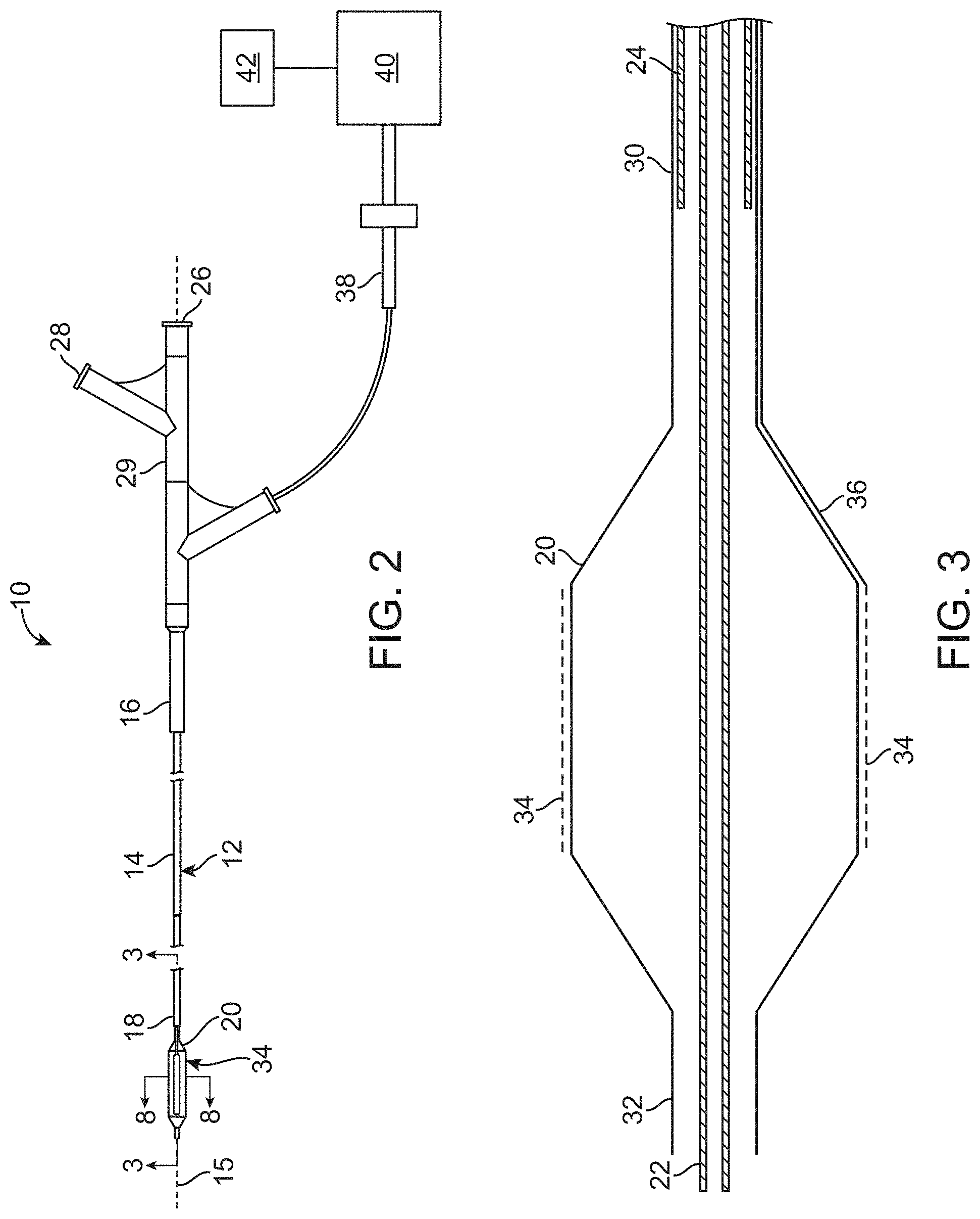
[0059] Balloon 20 is illustrated in more detail in FIG. 3. Balloon 20 generally includes a proximal portion 30 coupled to inflation lumen 24 and a distal portion 32 coupled to guidewire lumen 22. Balloon 20 expands radially when inflated with a fluid or a gas. In some embodiments, the fluid or gas may be non-conductive and/cooled. In some embodiments, balloon 20 may be a low pressure balloon pressurized to contact the artery tissue. In other embodiments, balloon 20 is an angioplasty balloon capable of higher pressure to both heat the artery tissue and expand the artery lumen. Balloon 20 may comprise a compliant or non-compliant balloon having helical folds to facilitate reconfiguring the balloon from a radially expanded, inflated configuration to a low profile configuration, particularly for removal after use.
[0060] Electrodes 34 are mounted on a surface of balloon 20, with associated conductors 36 extending proximally from the electrodes. Electrodes 34 may be arranged in many different patterns or arrays on balloon 20. The system may be used for monopolar or bipolar application of energy. For delivery of monopolar energy, a ground electrode is used, either on the catheter shaft, or on the patients skin, such as a ground electrode pad. For delivery of bipolar energy, adjacent electrodes are axially offset to allow bipolar energy to be directed between adjacent circumferential (axially offset) electrodes. In other embodiments, electrodes may be arranged in bands around the balloon to allow bipolar energy to be directed between adjacent distal and proximal electrodes.
[0061] Referring now to FIG. 4A, an exemplary balloon catheter structure having an array of electrodes thereon can be seen. FIG. 4B illustrates an exemplary RF generator for energizing the electrodes of the balloon catheter of FIG. 4A. The balloon catheter and RF generator of FIGS. 4A and 4B were used in a series of experiments on animal models, with the balloons having diameter sizes ranging from about 3 mm to about 8 mm. The test subjects comprised Healthy domestic swine and Yucatan Mini-Swine. Atherosclerotic disease was induced (Injury & HFHC diet), to demonstrate the ability of a system including the balloon catheter and RF generator of FIGS. 4A and 4B to deliver controlled therapy to artery walls. Histology was obtained at post-treatment endpoints to determine the extent of tissue damage and the appropriate treatment dose ranges.
[0062] Electrodes 34 may be mounted on balloon 20 using any suitable attachment. In the embodiment shown in FIG. 5A, electrodes 34 are mounted or made on a flexible substrate or "flexible circuit" 35 that is attached to the balloon 20 with a suitable adhesive. The associated conductors 36 are attached to the catheter body 14. The flexible circuit 35 should be flexible to allow folding and inflation of the balloon. Each flexible circuit 35 includes multiple pads 34, for example, a preferred embodiment includes sixteen pads arranged in a linear array electrode.
[0063] Referring now to FIG. 5B, a flexible circuit panel 110 having flexible circuits 112, 114, and 116 is shown. Each of the flexible circuits include electrically conductive leads 118 that extend between proximal electrical contacts 120 and distal electrodes 122. Leads 118 are supported by a flexible polymer substrate 124, and the flexible circuits may be used in catheter 12 (see FIG. 1), for example, by cutting the substrate around and/or between the electrical components of the circuit, mounting the electrodes to balloon 20, and extending leads 118 toward and/or along catheter body 14 for electrical coupling to controller or processor 40 and energy source 42. One or more flexible circuits may be mounted to balloon 20, with the electrodes of each flexible circuit optionally providing a grouping or sub-array of electrodes for treating a plurality of remodeling zones in the target tissue. Alternative sub-arrays may be provided among electrodes of different flexible circuits, may be defined by programmable logic of the processor, and/or may comprise any of a wide variety of alternative electrode circuit structures, with the sub-arrays often being employed for multiplexing or treating the region of target tissue with a plurality of differing electrical energy paths through the tissue.
[0064] Still referring to FIG. 5B, multiplexing between selected electrodes of an array or sub-array can be effected by selectively energizing electrode pairs, with the remodeling zones for the sub-array being disposed between the electrodes of the pairs so that the energy passes therethrough. For example, a pair of electrodes selected from electrodes 1, 2, 3, 4, 5, and 6 of flexible circuit 112 (with the selected electrodes optionally being positioned opposite each other) may be energized and then turned off, with another pair then being energized, and so forth. The firing order might be 1 and 4, then 2 and 5, then 3 and 6. Bipolar potentials between the electrodes of the pair can induce current paths in the same general tissue region, with the power dissipated into the tissue optionally remaining substantially constant. This provides a duty cycle of about 1/3 with respect to heat and/or losses at each electrode surface. The four electrode configurations of flexible circuits 114 and 116 could be used in a similar manner. Monopolar energy might also be applied using a larger ground pad on the skin of the patient or the like.
[0065] FIG. 5C shows flexible circuit panels 128 having flexible circuits 35 for use in FIG. 5A. Each of the flexible circuits 35 include electrically conductive leads 36 that extend between proximal electrical contacts 132 and distal electrodes 34. In the embodiment shown, each leg of flexible circuit 35 contains 16 electrodes 34 connected with one contact 132. This minimized the number of wires needed for conductive leads 36. The electrode pad may be 0.5 mm wide with 0.2 mm spacing between electrodes 34. The length and width of the electrode pad and number of electrodes may be changed for a desired impedance, for example, to match the impedance of the controller or generator. Leads 36 are supported by a flexible polymer substrate 134, and the flexible circuits may be used in catheter 12 (see FIG. 1), for example, by cutting the substrate around and/or between the electrical components of the circuit, mounting the electrodes to balloon 20, and extending leads 36 toward and/or along catheter body 14 for electrical coupling to controller or processor 40 and energy source 42. One or more flexible circuits may be mounted to balloon 20, with the electrodes of each flexible circuit optionally providing a grouping or sub-array of electrodes for treating a plurality of remodeling zones in the target tissue (See FIGS. 8A-8D). Alternative sub-arrays may be provided among electrodes of different flexible circuits, may be defined by programmable logic of the processor, and/or may comprise any of a wide variety of alternative electrode circuit structures, with the sub-arrays often being employed for multiplexing or treating the region of target tissue with a plurality of differing electrical energy paths through the tissue.
[0066] In one embodiment, a solid insulated wire of suitable size is flattened on a distal end, for example being coined or rolled, squashing the wire to create a shape appropriate for an electrode 34. The insulation along the coined surface is removed. In some embodiments, the wire is made of platinum, while in other embodiments, the coined surface is electroplated with gold. The wire and electrode are then placed in the correct position and adhered to the balloon 20.
[0067] FIG. 6A shows one embodiment in which electroplated portions 50 of a balloon 20 act as the electrodes 34 with an electrode base 52 placed on the inside of the balloon 20. In this embodiment, a portion of a balloon is electroplated so it may conduct electricity through its wall. Electroless plating or metal deposition may also be used. The wire-electrode 52 is adhered to the inside of the balloon with conductive epoxy 54, the balloon becomes the surface of the electrode 34. To minimize the current density within the wall of the balloon, the wire electrode may be in the same pattern as that electroplated on the balloon. The wire-electrodes may be manufactured from a wire 56 in a forging process similar to that used in the making of nails, shown in FIG. 6B. An end of a magnetic wire 56 is placed into a forging mold 58 so that a length of wire whose volume is equal to that of the desired electrode is extended into the mold and forged into the electrode base 52. The wire-electrode, with the exception of the electrode base, may be insulated, so that the electrodes are isolated from one another and from the fluid used for balloon inflation. This method will encapsulate the assembly, minimize the risk of electrode delamination, increase the manufacturing yield, and is adaptable to any desirable electrode shape and patterning.
[0068] In another embodiment, electrodes 34 contain materials of differing specific resistivity cured on the balloon 20. One example is using an excimer laser to selectively cure photocurable ink on the balloon. Thus, electrode pads and traces may bye directly mounted on the balloon. This process starts by covering the balloon with photocurable or photoimageable conductive ink. A laser is then used to direct write the traces and electrode pads (UV cure) The uncured conductive ink is then removed or rinsed off. A cover layer is placed over the entire balloon and circuits, such as a parylene coating. The parylene coating is then removed to expose the electrode pads, for example, using an excimer laser. The electrode pads are then coated with a conductive material, such as Ni/Au. In another embodiment, a direct drive laser printer is used to lay down a conductive ink circuit with electrode pads and traces on the balloon surface.
[0069] In some embodiments, small holes may be used to perfuse a fluid on or near the electrodes to eliminate sticking of the electrodes to the artery tissue. The holes may be less than 1 .mu.m in diameter and may be made with a laser or ion beam. The holes may be made in the electrodes, flexible circuit, and/or balloon. In one example, electrode pads on a flexible circuit are designed with vias that are plated. The flexible circuit is mounted on a balloon and a laser or ion beam is used to create the holes in the flexible substrate and balloon. There may be several holes in the flexible/balloon for every electrode pad. The balloon may then be perfused with standard perfusion balloon equipment or specialized equipment. The perfusion approach may also provide additional advantages beyond eliminating sticking, such as carrying away heat or regulating impedance of the load.
[0070] In some embodiments if may be advantageous to embed electrodes 34 into the artery tissue. The electrodes may have features to assist in imbedding, such as sharpened edges, needle protrusions, or the like, capable of piercing the artery tissue. For example, in a diseased tissue there will be some fibrous surface tissue surrounding the lumen that may tend to conduct energy, thereby avoiding the diseased tissue. This fibrous surface may tend to dominate any impedance measurement if they are probed superficially. By digging the electrodes into the wall of the fibrous cap, it may be possible to direct energy through the fibrous tissue directly into the diseased tissue, or closer to the diseased tissue. The energy may be Joule heating or a current source that puts more heating into the diseased tissue with higher resistively. The healthy tissue can dissipate the energy without significant damage. This technique may also assist in detecting diseased tissue electrically.
[0071] Monitoring the space between electrodes or electrode flexible circuits during inflation may assist in determining the direction of diseased tissue within an artery. The space between pairs of electrodes increases with pressure in an elastic balloon when it is unconstrained during inflation. When a balloon is placed within an eccentrically effected diseased tissue, the diseased portion stretches less than the healthy tissue. So the change in the distance between the pairs changes more in the healthy tissue and less in the diseased tissue, indicating the direction, and maybe the amount, of diseased tissue in the artery.
[0072] Monopolar Treatment
[0073] FIG. 7A shows one embodiment of balloon catheter system for use for monopolar treatment of diseased tissue in a leg. A balloon catheter 20 having electrodes 34 are positioned within an artery lumen 60 having diseased tissue 62. An electrical ground 64 is positioned on the patients skin, or may be many ground electrode pads 68 positioned around a patients leg 66, such a in a band or sock. When power is applied to the multiple monopolar electrodes 34 arranged around the circumference of the artery lumen, energy 70 is directed radially outward through the artery wall.
[0074] By driving energy 70 radially outward, it is possible to force energy through the disease tissue 62, which has a higher electrical resistivity than healthy tissue. By applying low power for a long time duration, the disease tissue may be treated. Low power is defined as the level of power which healthy tissue can dissipate the heat in a steady state without the healthy tissue temperature rising above a given threshold. The temperature may be between 45.degree. C. and 50.degree. C., which will denature the actin and myosin proteins that enable elastic recoil, without causing excessive necrosis. The energy may be applied for a long time, where long is defined by the desired duration of the procedure, bounded on the high side by the amount of time healthy tissue can withstand the elevated temperature being caused, and bounded on the low side by the amount of time the diseased tissue needs for treatment to be complete. By treating for a long time, it is possible to accumulate heat in the diseased tissue, which has a lower heat capacity per mass and a lower thermal conductivity. Variability in impedance can be compensated by the controller, in order to apply either constant power, constant current, or constant voltage, whichever has the most advantage.
[0075] The energy in the monopolar treatment shown if FIG. 7A travels outwardly from the electrodes 34 and treats both diseased 62 and healthy artery tissue. Looking at the current path in tissue, diseased artery tissue, such as fat or lipidic material, has a low electrical conductivity compared to other artery constituents. If this is true, the current 70 may go around the diseased tissue 62 if possible, and find a less restrictive path, such as shown in FIG. 7B.
[0076] In some embodiments, internal 34 and external electrodes 68 may be used to map artery plaque. By assembling a matrix of impedance readings, both bipolar and monopolar, it may be possible to map the constituent composition and location of the disease in the artery. Once this information in known, it may be possible to treat using the same known electrode positions. The treatment can either by monopolar or bipolar. Analysis is done weighting the contributions of the distance between the internal and external electrodes with the contribution differences in cellular composition in each path. Design of the external electrodes 68 may be guided by computational capacity, maximizing the number of electrode points both around the circumference and along the patients leg (lengthwise). In one embodiment, the external electrodes 68 are embedded in a sock or sleeve forming a matrix of electrodes on the outside of the patients skin. This may device gives improved resolution in measuring current paths from multiple directions and provides a way to identify what the internal electrodes are opposed to in the artery.
[0077] Bipolar Treatment
[0078] FIGS. 8A-8D show different embodiments of electrodes 34 mounted circumferentially on balloon 20 to provide treatment to artery tissue using bipolar energy between electrode pairs 34A and 34B. The electrode pairs may be any electrode pairs on the balloon, for example, in some embodiments, the electrode pairs may be 34A and 34C, or 34A and 34D, or 34A and 34E, or any combination of 34A-34E. This arrangement creates an energy path through the tissue that delivers heat or energy in particular treatment zones or segments 72 to the artery tissue between the electrode pairs ("remodeling zones"). Using different combinations of electrode pairs may reduce or eliminate gaps between the remodeling zones by using overlapping pairs. Using electrode pairs with bipolar energy may avoid some potential issues of the monopolar approach. Diseased artery tissue has a higher electrical resistively than healthy artery tissue. If all the electrodes are energized, such as in a monopolar system, the heat or energy may flow through the healthy artery tissue and not into the diseased artery tissue (see FIG. 7B). By using pairs of electrodes in a bipolar system, the heat or energy will go through the healthy tissue, diseased tissue, or a combination of both healthy and diseased tissues between the electrode pairs in the remodeling zones. Any number of electrode pairs may be used in different patterns or arrays. In the embodiments shown, the pitch between electrode pairs remains the same, for example 3.14 mm, so that the treatment volume is the same regardless of balloon size and each of the electrode pairs use the same energy. As the balloons become larger, more electrode pairs are placed on the balloon, such as shown in FIGS. 8A-8D. The spacing between electrode pairs may range from about 0.25 to 2.5 mm, depending on balloon size. The maximum distance (angle) between electrode pairs is 180 degrees on the balloon. FIG. 8A shows a balloon having a 3.0 mm diameter with three electrode pair in three segments 72A. FIG. 8B shows a balloon having a 4.0 mm diameter with four electrode pair in four segments 72B. FIG. 8C shows a balloon having a 5.0 mm diameter with five electrode pair in five segments 72C. FIG. 8D shows a balloon having a 6.0 mm diameter with six electrode pair in six segments 72D.
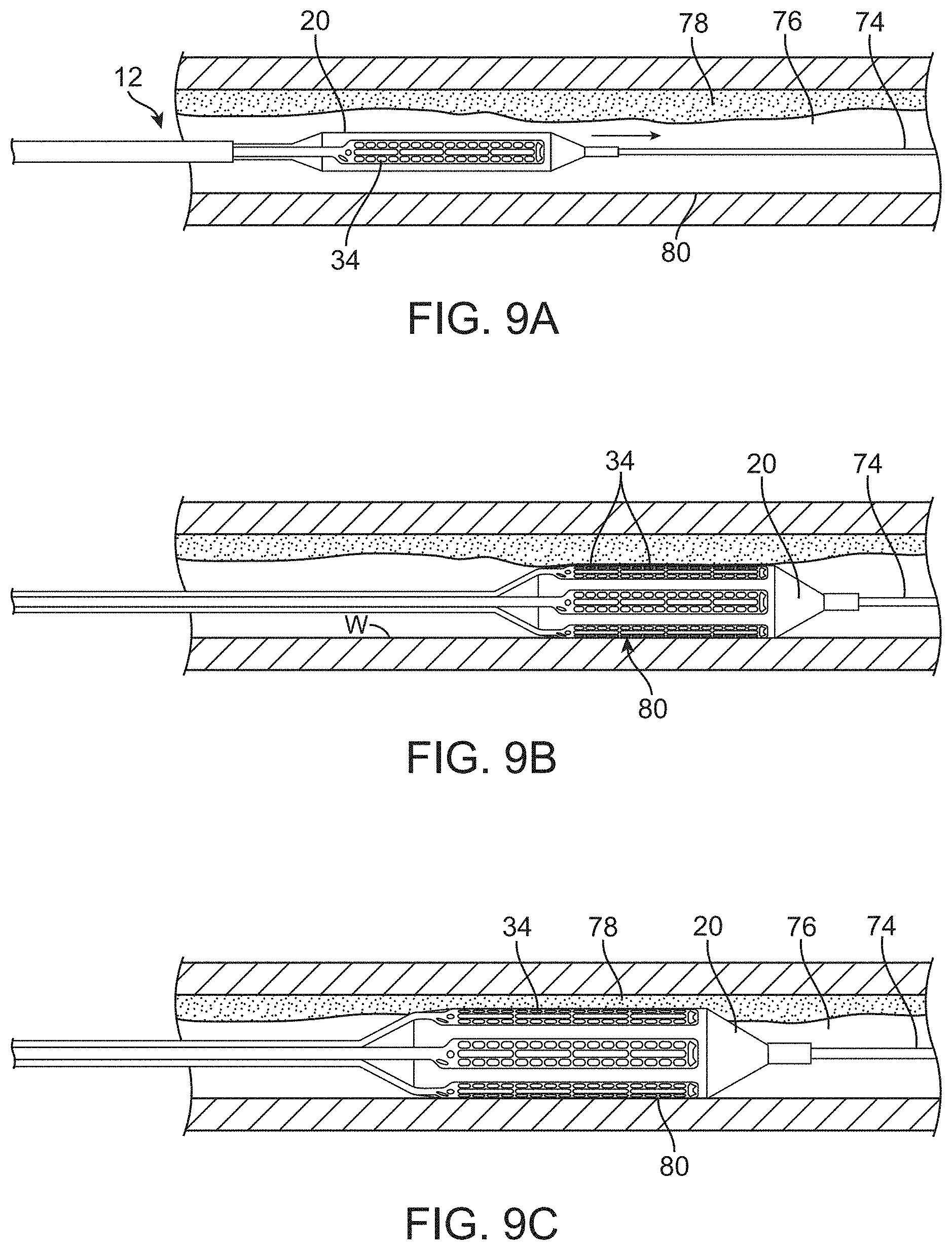
[0079] The use of catheter system 10 for remodeling artery tissue by heating can be understood with reference to FIGS. 9A-9C. As seen in FIG. 9A, accessing of a treatment site will often involve advancing a guidewire 74 within a blood vessel 76 at a target region of diseased tissue, such as atherosclerotic material 78. Location of balloon 20 may be facilitated by radiopaque markers or by radiopaque structure (or corresponding radiopaque markers placed on or near) balloon 20, and/or by the use of radiopaque electrodes 34. A wide variety of guidewires may be used. For accessing a vessel having a total occlusion, guidewire 74 may comprise any commercially available guidewire suitable for crossing such a total occlusion, including the Safe-Cross.TM. RF system guidewire having forward-looking optical coherence reflectrometry and RF ablation. Where atherosclerotic material does not result in total occlusion of the lumen, such capabilities need not be provided in guidewire 74, although other advantageous features may be provided. Guidewire 74 may be positioned under fluoroscopic (or other) imaging.
[0080] Catheter 12 is advanced distally over guidewire 74 and positioned adjacent to atherosclerotic material 62. Balloon 20 expands radially within the lumen of the blood vessel so that electrodes 34 radially engage atherosclerotic material 78. As atherosclerotic material 78 may be distributed eccentrically about catheter 12, some of electrodes 34 may engage both atherosclerotic material 78 and healthy tissue 80, as can be understood with reference to FIGS. 9B and 9C.
[0081] In some cases, an imaging may be used for identification and/or characterization of atherosclerotic materials, plaques, tissues, lesions, and the like from within a blood vessel. Suitable imaging catheters for use in the present catheter system are commercially available from a wide variety of manufacturers. Suitable technology and/or catheters may, for example, be commercially available from SciMed Life Systems and Jomed-Volcano Therapeutics (providers of intravascular ultrasound catheters), Light Lab.TM. Imaging (developing and commercializing optical coherence tomography catheters for intravascular imaging), Medtronic CardioRhythm, and the like. Still further alternative technologies may be used, including ultra fast magnetic resonance imaging (MRD, electrical impedance atheroma depth measurements, optical coherence reflectrometry, and the like. Non-invasive imaging modalities which may be employed include X-ray or fluoroscopy systems, MRI systems, external ultrasound transducers, and the like. Optionally, external and/or intravascular atherosclerotic material detectors may also be used to provide temperature information. For example, a system having an MRI antenna may detect tissue temperatures such that a graphical indication of treatment penetration may be presented on the system display. Tissue temperature information may also be available from ultrasound and/or optical coherence tomography systems, and the temperature information may be used as feedback for directing ongoing treatments, for selecting tissues for treatment (for example, by identifying a hot or vulnerable plaque), and the like.
[0082] As discussed above, electrodes 34 are positioned circumferentially around the balloon 20. RF energy is directed to electrodes adjacent pairs of electrodes 34A and 34B, treating both atherosclerotic material 78 and the healthy tissue 80. The controller 40 may energize the electrodes with about 0.25 to 5 Watts average power for 1 to 180 seconds, or with about 4 to 45 Joules. Higher energy treatments are done at lower powers and longer durations, such as 0.5 Watts for 90 seconds or 0.25 Watts for 180 seconds. Most treatments in the 2 to 4 Watt range are performed in 1 to 4 seconds. Using a wider electrode spacing, it would be appropriate to scale up the power and duration of the treatment, in which case the average power could be higher than 5 Watts, and the total energy could exceed 45 Joules. Likewise, using a shorter or smaller electrode pair would require scaling the average power down, and the total energy could be less than 4 Joules. The power and duration are calibrated to be less than enough to cause severe damage, and particularly less than enough to ablate diseased tissue 48 within a blood vessel. The mechanisms of ablating atherosclerotic material within a blood vessel have been well described, including by Slager et al. in an article entitled, "Vaporization of Atherosclerotic Plaque by Spark Erosion" in J. of Amer. Cardiol. (June, 1985), on pp. 1382-6; and by Stephen M. Fry in "Thermal and Disruptive Angioplasty: a Physician's Guide;" Strategic Business Development, Inc., (1990) the full disclosures of which are incorporated herein by reference.
[0083] Referring now to FIG. 7C, as described above, balloon 20 may be an angioplasty balloon that combines heating with opening the artery lumen. In some embodiments, injury caused to the atherosclerotic material with the energized electrodes or other energy directing surfaces may result in subsequent resorption of the injured tissue lesions so as to provide further opening of the vessel after termination of treatment as part of the healing process.
[0084] In some embodiments, balloon 20 may be repeatedly contracted, axial movement of the catheter 12 employed to reposition balloon 20, with subsequent expansion of balloon 20 at each of a plurality of treatment locations along atherosclerotic material 78.
[0085] The exemplary catheter devices and methods for their use described herein are intended for application in the lumen of vessels of the human anatomy. The anatomical structure into which the catheter is placed may be, for example, the esophagus, the oral cavity, the nasopharyngeal cavity, the auditory tube and tympanic cavity, the sinus of the brain, the arterial system, the venous system, the heart, the larynx, the trachea, the bronchus, the stomach, the duodenum, the ileum, the colon, the rectum, the bladder, the ureter, the ejaculatory duct, the vas deferens, the urethra, the uterine cavity, the vaginal canal, and the cervical canal.
[0086] Frequency targeting of tissues is illustrated in FIG. 10. Different tissue types have different characteristic electrical impedances that cause the tissue to absorb energy of certain frequencies or frequency ranges more readily than others. By applying energy at the specific frequency or range of frequencies that the tissue is more conductive, energy penetrates the tissue more readily. In general, it has been shown that samples of diseased tissue exhibit higher impedance characteristics than samples of healthy tissue. In the case where a diseased area of tissue 78 is surrounded by relatively healthy tissue 80, the healthy tissue is likely to shield the diseased tissue from electrical current flow due to the lower impedance of the healthy tissue. Hence, minimal (or less than the desired) current flow 82 may pass through diseased tissue 78, and heavier current flow 84 may be seen in low impedance healthy tissue 80 when bipolar current is transmitted between electrodes 34A and 34B. Typically, the frequency ranges in which tissue impedance varies to a useful degree occur between 30 kilohertz and 30 Megahertz.
[0087] Frequency targeting seeks to deliver more energy to the diseased tissue by determining the frequency or range of frequencies at which the impedance of the diseased tissue is equal to or less than that of the healthy tissue, such as by operation at or above a threshold frequency. Energy delivered at the specified frequency or range of frequencies will cause more heat to be dissipated in the diseased tissue than energy delivered outside of those specific frequencies.
[0088] FIG. 11 shows some results of testing done on a cadaver aorta. By using an average power between 1 and 5 Watts for between 0.5 and 10 seconds the surface temperature reached was between 50 and 65.degree. C. Sample doses are shown below in Table 1
TABLE-US-00001 TABLE 1 Power Time Temp 1 Watt 8 sec 50.degree. C. 2 Watts 2 sec 50.degree. C. 3 Watts 1.3 sec 50.degree. C. 4 Watts 1 sec 50.degree. C. 5 Watts .5 sec 50.degree. C. 2 Watts 4 sec 60.degree. C. 3 Watts 2 sec 60.degree. C. 4 Watts 1.5 sec 60.degree. C. 5 Watts 1 sec 60.degree. C. 3 Watts 3 sec 65.degree. C. 4 Watts 2 sec 65.degree. C.
[0089] As the energies and powers for characterizing and/or treating tissues are relatively low, the power source may optionally make use of energy stored in a battery, with the power source and/or associated controller optionally being contained within a hand-held housing. Use of such battery-powered systems may have benefits within crowded operating rooms, and may also help avoid inadvertent over treatment. The batteries may be disposable structures suitable to be included in a kit with a single-use catheter, while the processor circuitry may be re-useable. In other embodiments, the batteries may be rechargeable.
[0090] Electrode Design Considerations
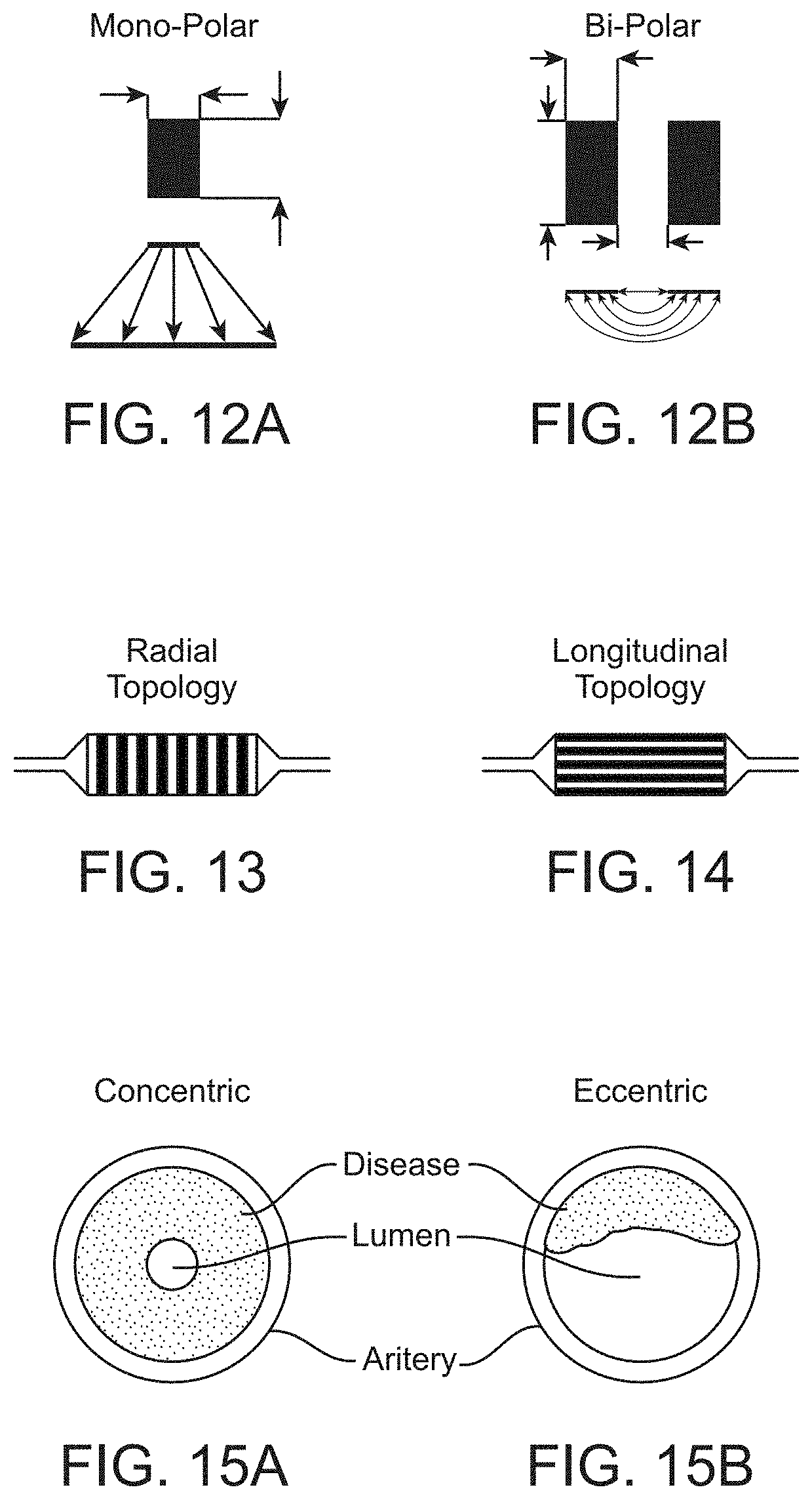
[0091] Delivering RF energy directly to a specimen requires a conductive path to be formed between two terminals or poles of an energy source. Currently there are two polar configurations that exist which satisfy this condition: a mono-polar configuration (FIG. 12A) and a bipolar configuration (FIG. 12B). In a mono-polar configuration there is a single pole or electrode from which the energy emanates and a grounding plate or pad to absorb the energy and complete the circuit. This configuration creates higher energy densities at the electrode than at the grounding pad which results in a single effected area or treatment zone at the electrode which is directly related to the geometry of the electrode and the power applied to the electrode. As the surface area of the mono-polar electrode increases, so does the size of the treatment zone. The bi-polar configuration, on the other hand uses two poles or electrodes to set up an electric field between the electrodes thus creating a conduction path for the current to flow. Unlike the mono-polar electrode configuration where only one geometric entity, surface area is deterministic to the treatment zone, the bi-polar electrode configuration has three, electrode separation, parallel length and width, each of which have a separate and distinct effect on the treatment zone.
[0092] If we take into consideration the effect each geometric entity has on the effected treatment zone and the overall impedance as seen by the generator, we find that the separation or distance between electrodes has the greatest effect, followed by parallel length and lastly electrode width. Electrode separation is governed by Coulombs law which states that the force between two charged objects is inversely proportional to the square of the distance between them. In other words at very close distances the impedance as seen by a generator is very small and as we separate the electrodes the impedance increases at a rate that is proportional to the square of their separation. As this separation increases, a higher potential energy is generated due to the increase in impedance creating a greater flux density which results in a greater treatment depth. The effect of increasing the parallel length shared by the two electrodes causes the treatment zone to increase only as much as the parallel electrode length is increased. There are no additional depth effects only an increase due to added length. This additional length causes the impedance as seen by the generator to decrease due to the increase in potential parallel paths for the current to flow through. Electrode width has the least effect on the treatment zone and is governed by the same laws as electrode separation. As the width of the electrode is increased incrementally, the added effect is small due to the inverse square law for each incremental element placed on the outer edges of the existing electrode elements. Although this effect may be small it aides in reducing the surface heat generated by reducing the current density at the inside edge of the electrode pairs. This effect is amplified as the conductance of the electrode material approaches the conductance of the tissue being treated due to the path of least resistance becoming the tissue rather than the electrode itself.
[0093] In order to better control the flow of electrical current to the inside of the arterial wall and to have a therapy which has the capability to selectively treat a desired area of an artery, the bipolar configuration is clearly the most desirable method of implementation.
[0094] Implementation requires that the electrodes be in contact with the inner surface of the arterial wall so the conductive path is the artery itself and not the more conductive blood flowing within the artery. Many mechanism may be used to contact the electrodes to the inner surface of the arterial wall. In the present case, a balloon is used as the deployment mechanism. The bipolar electrodes may be arranged on the balloon either a radial topology (FIG. 13) or a longitudinal topology (FIG. 14).
[0095] Each topology, radial and longitudinal, provides for a bi-polar configuration as well as offer a selective therapy, however the method of selectivity of each topology differ. The radial topology offers longitudinal selectivity along the length of an artery while the longitudinal topology offers circumferential selectivity. When we then take into consideration how atherosclerosis forms within an artery, we find that it starts out at a localized area on the arterial wall and spreads along the wall sometimes completely occluding the flow of blood. In the case of complete occlusion or stenosis where the diseased tissue is concentric about the entire circumference of the artery (FIG. 15A), each topology will suffice. However, in the case where the diseased tissue is eccentric and a portion of the artery is still healthy tissue (FIG. 15B), the longitudinal topology is preferred due to the difference in thermal and electrical conductivity between the healthy tissue and diseased tissue. This difference, in the case of the radial topology will cause the healthy portion to be treated more than the disease which is not a desirable outcome. When we also take into consideration that the balloon must first be folded to reduce the cross sectional area for deployment, it becomes clear that the longitudinal topology appears to be the better choice.
[0096] The next was how to arrange the electrode on the balloon. How long should the electrodes be? How wide should the electrodes be? And how far apart should the electrodes be separated? An initial starting point was to use four balloon diameters, 3 mm, 4 mm, 5 mm and 6 mm. An electrode geometry configuration was designed so that each balloon diameter would be capable of accepting the same electrode geometry configurations, so no matter what size balloon was being used, the treatment could be the same. With this configuration, the basic relationship of the circumference of the balloon is related to the diameter by the factor of .pi. (pi). The circumference of the balloon is equal to its diameter multiplied by .pi. (pi). Using the balloon diameters to dictate the number of electrode pairs placed on a balloon, the center to center electrode spacing would be .pi. (pi) divided by 2. This configuration allows for the even distribution of electrodes about the circumference of the balloon for each whole number balloon diameter. With the electrodes center to center spacing decided, next is to figure out the ratio of the electrodes width to their separation. This ratio would have to take in to consideration the desired depth of treatment, as well as the effects of surface heating. Taking these factors into consideration, a ratio of approximately 1:2 was selected. The actual numbers used were an electrode width of 0.5 mm with a spacing of 1.07 mm, which fits nicely with the .pi./2 center to center separation. This selected configuration also allowed twice the number of possible treatment zones for each balloon diameter (2n) as compared to one electrode pair for each millimeter of balloon diameter. Having twice the number of available treatment zones also meant that there was a greater potential for selectivity.
[0097] The last geometric entity yet to be decided was the length of the electrodes. When trying to measure the impedance of the tissue the electrodes are in contact with, it is more desirable to implement shorter electrodes so there is more sensitivity in the measurement and also more immunity to noise. Shorter electrodes on the other hand also mean that to treat an adequate area there needs to be many more electrode pairs and as a result more wires connecting those electrodes to the generator which will ultimately decrease the flexibility and complexity of the catheter. If long electrodes are used to reduce the wire count and to increase the potential treatment area, a different set of problems arise. Although long electrodes allow for a potentially larger treatment zone, they also allow for the possibility of overlapping into a healthy area which would result in an uneven treatment which could preferentially treat the healthy area rather than the diseased. The other disadvantage is the reduced sensitivity when measuring impedance due to the increase in available current paths which also results in the need for larger diameter wires to accommodate the increased current requirements. In solving this problem available balloon lengths were looked at and 16 mm electrodes were chosen to use on a 20 mm balloon. This selection allowed for reasonable sensitivity while keeping the wire size to a minimum.
[0098] There are many available methods for placing electrodes onto a balloon, ranging from vapor deposition to flexible circuitry to individual machined electrode and flattened wire. The main consideration was a proven manufacturing method, materials that could be placed in the body and parts that could be handled fairly easily without damage. Taking these factors into consideration, the use of flexible circuitry was chosen as the method to manufacture the electrodes. Flexible circuitry met all of the above criteria while still being flexible after being mounted to the balloon. When designing the flexible electrodes, the design should ensure that the electrodes are in firm contact with the arterial wall, evacuating as much of the blood as possible. To achieve this, individual rounded pads were selected that were 0.5 mm wide by 0.8 mm long separated by a distance of 0.2 mm. Pads were connected together in "string" using 0.5 oz Cu traces with 0.5 mil polyimide on the front and back and between electrode pads providing insulation and isolation. The pads were then plated up so the finished pad height was above polyimide cover-lay. The 0.2 mm separation between connected pads was implemented to retain flexibility and to ensure the connection was maintained during flexing. An electroless nickel-immersion gold coating was used to cover all exposed copper for safety. These electrodes were then adhered to the balloon using a flexible UV cured adhesive.
[0099] Referring now to FIG. 16, suitable power ranges for providing the desired heating of the target tissue, and/or for limiting of heating to collateral tissues, may depend at least in part on the time for which energy is applied, on the electrode (or other energy transmitting surface) geometry, and the like. First, when applying the treatments described herein to tissues with electrodes, there may be preferred a load impedance range of the tissues within the circuit so as to avoid having to apply voltages and/or currents that are outside desirable ranges, particularly when applying powers within ranges described herein. Suitable load impedance ranges would generally be within a range from about 20 Ohms to about 4500 Ohms, more typically being in a range from about 40 Ohms to about 2250 Ohms, and preferably being in a range from about 50 to about 1000 Ohms.
[0100] The load impedance of the tissue within the circuit may depend on the characteristics of the tissue, and also (for example) on the geometry of a bipolar pair of electrodes that engage the tissue, as the electrodes geometries influence the geometry of the tissue effectively included within the circuit. The tissue to which energy is directed may have a specific conductivity in a range from about 0.2 Siemens per meter to about 0.5 Siemens per meter. Different types of diseased tissues may have specific conductivities in different ranges, with some types of diseased tissues having specific conductivities in a range from about 0.2 Siemens per meter to about 0.35 Siemens per meter, while others fall within a range from about 0.35 Siemens per to about 0.5 Siemens per meter. The spacing between the pair of electrodes and the length of electrodes (transverse to their spacing) will both have effects on the load impedance, with most embodiments having electrode pair spacings (adjacent edge-to-edge) of between 0.25 mm and 2.50 mm, exemplary embodiments having electrode pair spacing of between 0.50 and 2.00 mm, and preferred embodiments having electrode pair spacing of between 0.75 and 1.50 mm.
[0101] Regarding the length and spacing of the electrodes within a particular pair, these factors are inter-related with the power and impedance. As the length of the electrodes decreases, the impedance seen by the generator will go up, but the volume of tissue will go down, so that the power setting on the generator may be decreased. As the gap between the electrodes widens, the impedance seen by the generator will also go up, but the volume of tissue will go up as well, so that the power setting on the generator should be increased. Hence, there are roughly opposed effects on load impedance when you decrease electrode length and electrode spacing.
[0102] Desired power, energy, and time of the treatment are likewise inter-related, and may also be at least related with electrode geometry. Speaking very generally, lower power treatments applied for long times tends to result in treatments with relatively higher total energies, while higher power treatments for shorter times tends to result in lower energy treatments. More specifically, at relatively low average power (1 W or less) the total energy delivery per treatment may range from 8 to 45 Joules. At higher power (more than 1 W), the total energy delivery per treatment may range from 4 to 15 Joules. If the electrode spacing were doubled, power may increase by four times. The power transmitted into the tissue can be calibrated and scaled to the particular electrode configuration, often in order to keep the power and energy density in a desirable range. Exemplary power ranges may be, for example from about 1 to 5 Watts. The duration is longer for the lower power settings, and typically varies from about 1 to 8 seconds. Very low power settings less than 1 Watt are also possible, using durations much longer than 10 seconds.
[0103] It is also possible to scale the power settings significantly by varying the electrode configuration. If, for instance, the inner edge-to-edge spacing of the electrodes are increased, roughly 4 times the power may be applied because the volume of tissue becomes roughly 4 times larger. As such, an electrode configuration that is somewhat different from the exemplary embodiments described herein could be used within a power range of roughly 4 to 20 Watts. Shortening the electrodes, and thus shortening and reducing the volume of the remodeling zones, would also affect the magnitude of the power that is appropriate to apply to the tissue volume.
[0104] Referring still to FIG. 16, in order to quantify this complex set of relationships, and bound the space within which the exemplary treatment device can operate, an empirical relationship between safe values of several of these parameters may be generated and provided graphically, in table form, or by a mathematical relationships. An exemplary equation describing a particularly advantageous relationship is:
power=b*x{circumflex over ( )}2*L*(t{circumflex over ( )}(-0.59))
where b is a parameter in the range of 0.2 to 0.6, x is the inner edge-to-edge spacing of the electrodes in millimeters, L is the length of the electrodes in millimeters (and also the approximate length of the remodeling zone), the power is in Watts, and t is time in seconds. b has units of Watts/(mm{circumflex over ( )}3)*(seconds{circumflex over ( )}0.59). Exemplary treatments in the range described by this equation includes treatments such as 4 Watts for 2 seconds, 3 Watts for 3 seconds, 2 Watts for 4 seconds, and 1 Watt for 12 seconds with the exemplary electrode geometries described herein. Additionally, very low power long duration treatments such as 0.25 Watts for 180 seconds are covered as well. Alternative suitable treatment range falls within or near the set of curves shown in FIG. 16, which shows approximate numbers for maximum power and time by electrode dimensions. Still further alternative treatment parameter values can be understood with reference to Table 2, which shows total energies for different combinations of power and time for a few different electrode pair geometries.
TABLE-US-00002 TABLE 2 Alternative I Alternative II Exemplary Peripheral Peripheral Treatment Peripheral Treatment Exemplary Coronary Treatment Catheter Catheter Catheter Treatment Catheter X = 1 mm, X = 2 mm, X = 2 mm, X = 0.5 mm, L = 16 mm Total L = 16 mm Total L = 8 mm Total L = 8 mm Total Time Power Energy Time Power Energy Time Power Energy Time Power Energy (s) (W) (J) (s) (W) (J) (s) (W) (J) (s) (W) (J) 1 5 5 1 20 20 1 10 10 1 0.625 0.625 2 4 8 2 16 32 2 8 16 2 0.5 1 3 3 9 3 12 36 3 6 18 3 0.375 1.125 4 2 8 4 8 32 4 4 16 4 0.25 1 12 1 12 12 4 48 12 2 24 12 0.125 1.5 30 0.5 15 30 2 60 30 1 30 30 0.0625 1.875 180 0.25 45 180 1 180 180 0.5 90 180 0.03125 5.625
[0105] While the exemplary embodiments have been described in some detail, by way of example and for clarity of understanding, those of skill in the art will recognize that a variety of modification, adaptations, and changes may be employed. Hence, the scope of the present invention should be limited solely by the appending claims.
* * * * *
D00000
D00001
D00002
D00003
D00004
D00005
D00006
D00007
D00008
D00009
D00010
D00011
D00012

XML
uspto.report is an independent third-party trademark research tool that is not affiliated, endorsed, or sponsored by the United States Patent and Trademark Office (USPTO) or any other governmental organization. The information provided by uspto.report is based on publicly available data at the time of writing and is intended for informational purposes only.
While we strive to provide accurate and up-to-date information, we do not guarantee the accuracy, completeness, reliability, or suitability of the information displayed on this site. The use of this site is at your own risk. Any reliance you place on such information is therefore strictly at your own risk.
All official trademark data, including owner information, should be verified by visiting the official USPTO website at www.uspto.gov. This site is not intended to replace professional legal advice and should not be used as a substitute for consulting with a legal professional who is knowledgeable about trademark law.