Mop Assemblies And Accessories
Wu; Weidong
U.S. patent application number 16/456828 was filed with the patent office on 2020-01-02 for mop assemblies and accessories. The applicant listed for this patent is Rubbermaid Commercial Products, LLC. Invention is credited to Weidong Wu.
| Application Number | 20200000307 16/456828 |
| Document ID | / |
| Family ID | 67441622 |
| Filed Date | 2020-01-02 |


| United States Patent Application | 20200000307 |
| Kind Code | A1 |
| Wu; Weidong | January 2, 2020 |
MOP ASSEMBLIES AND ACCESSORIES
Abstract
Mop assemblies and accessories for cleaning are provided. A mop head includes an elongated body having a length dimension that is greater than a width dimension, the elongated body having a cleaning side and an opposed backside, and a plurality of fabric ribs defining a plurality of channels therebetween, the plurality of fabric ribs extending from the cleaning side of the elongated body.
| Inventors: | Wu; Weidong; (Charlotte, NC) | ||||||||||
| Applicant: |
|
||||||||||
|---|---|---|---|---|---|---|---|---|---|---|---|
| Family ID: | 67441622 | ||||||||||
| Appl. No.: | 16/456828 | ||||||||||
| Filed: | June 28, 2019 |
Related U.S. Patent Documents
| Application Number | Filing Date | Patent Number | ||
|---|---|---|---|---|
| 62691356 | Jun 28, 2018 | |||
| Current U.S. Class: | 1/1 |
| Current CPC Class: | A47L 13/16 20130101; A47L 13/252 20130101; A47L 13/254 20130101 |
| International Class: | A47L 13/252 20060101 A47L013/252 |
Claims
1. A mop head, comprising: an elongated body having a length dimension that is greater than a width dimension, the elongated body comprising a cleaning side and an opposed backside; and a plurality of fabric ribs defining a plurality of channels therebetween, the plurality of fabric ribs extending from the cleaning side of the elongated body.
2. The mop head of claim 1, wherein the elongated body further comprises a layer of foam disposed between the cleaning side and the backside.
3. The mop head of claim 2, wherein the foam comprises polyurethane, polyethylene, or sponge material.
4. The mop head of claim 1, wherein the elongated body further comprises a layer of fabric disposed between the cleaning side and the opposed backside.
5. The mop head of claim 4, wherein the layer of fabric comprises polyester, nylon, or cotton.
6. The mop head of claim 1, wherein the plurality of fabric ribs extend across the cleaning side substantially in the length, width, or diagonal direction.
7. The mop head of claim 1, wherein the plurality of channels extend across the cleaning side substantially in the length, width, or diagonal direction.
8. The mop head of claim 1, further comprising stitching securing the plurality of fabric ribs on the cleaning side to define the plurality of channels.
9. The mop head of claim 8, wherein the stitching comprises a series of lock stitching and a series of overlock stitching.
10. The mop head of claim 1, wherein the plurality of fabric ribs are defined by a continuous fabric sheet.
11. The mop head of claim 10, wherein the continuous fabric sheet comprises rayon, polyester, nylon, cotton, wool, or microfiber.
12. The mop head of claim 1, wherein the plurality of fabric ribs have a height of from about 0.5 to about 10 centimeters.
13. The mop head of claim 1, wherein plurality of fabric ribs have a height of from about 2.4 to about 3.6 centimeters.
14. The mop head of claim 1, wherein the plurality of channels have a width of from about 0.2 to about 10 centimeters.
15. The mop head of claim 1, wherein the plurality of channels have a width of about 2.0 to about 3.8 centimeters.
16. The mop head of claim 1, wherein each of the plurality of fabric ribs comprises an arcuate exterior defining an internal volume.
17. The mop head of claim 1, further comprising a binding material disposed about an edge of the elongated body, the binding material coupling the cleaning side and the opposed backside.
18. The mop head of claim 1, wherein the mop head is configured to be launderable.
19. The mop head of claim 1, further comprising a hang loop coupled to the elongated body.
20. The mop head of claim 1, wherein the mop head is selectively attachable to an attachment mechanism of a mop handle.
Description
CROSS-REFERENCE TO RELATED APPLICATIONS
[0001] This application claims priority benefit of U.S. Provisional Application No. 62/691,356, filed Jun. 28, 2018, which is incorporated by reference herein.
BACKGROUND
[0002] The present disclosure relates generally to mops, and relates more particularly to mops configured to gather both large and small particles.
[0003] Mops are commonly characterized as wet mops or dry mops. Understandably, wet mops are primarily used for absorbing and cleaning spilled liquids. Conversely, dry mops are used for gathering dirt, dust, and other types of debris. Traditional dry mops cover a large surface area and capture particles by trapping the debris within the fibers of the mop. To clean the dry mop after picking up the various dirt and debris is to simply shake and/or pat the mop over a trash receptacle. Therefore, the dry mop can be a handy tool for cleaning, and any improvement in the number as well as the size of particles a dry mop can pick up would be useful for improving cleaning efficiency.
SUMMARY
[0004] In one aspect, a mop head is provided, including an elongated body having a length dimension that is greater than a width dimension, the elongated body having a cleaning side and an opposed backside, and a plurality of fabric ribs defining a plurality of channels therebetween, the plurality of fabric ribs extending from the cleaning side of the elongated body.
[0005] In another aspect, a mop assembly is provided, including an elongated mop handle and a mop head operably coupled to the mop handle.
BRIEF DESCRIPTION OF THE DRAWINGS
[0006] Referring now to the drawings, which are meant to be exemplary and not limiting, and wherein like elements are numbered alike. The detailed description is set forth with reference to the accompanying drawings illustrating examples of the disclosure, in which use of the same reference numerals indicates similar or identical items. Certain embodiments of the present disclosure may include elements, components, and/or configurations other than those illustrated in the drawings, and some of the elements, components, and/or configurations illustrated in the drawings may not be present in certain embodiments.
[0007] FIG. 1 is a plan view of the cleaning side of one embodiment of a mop head.
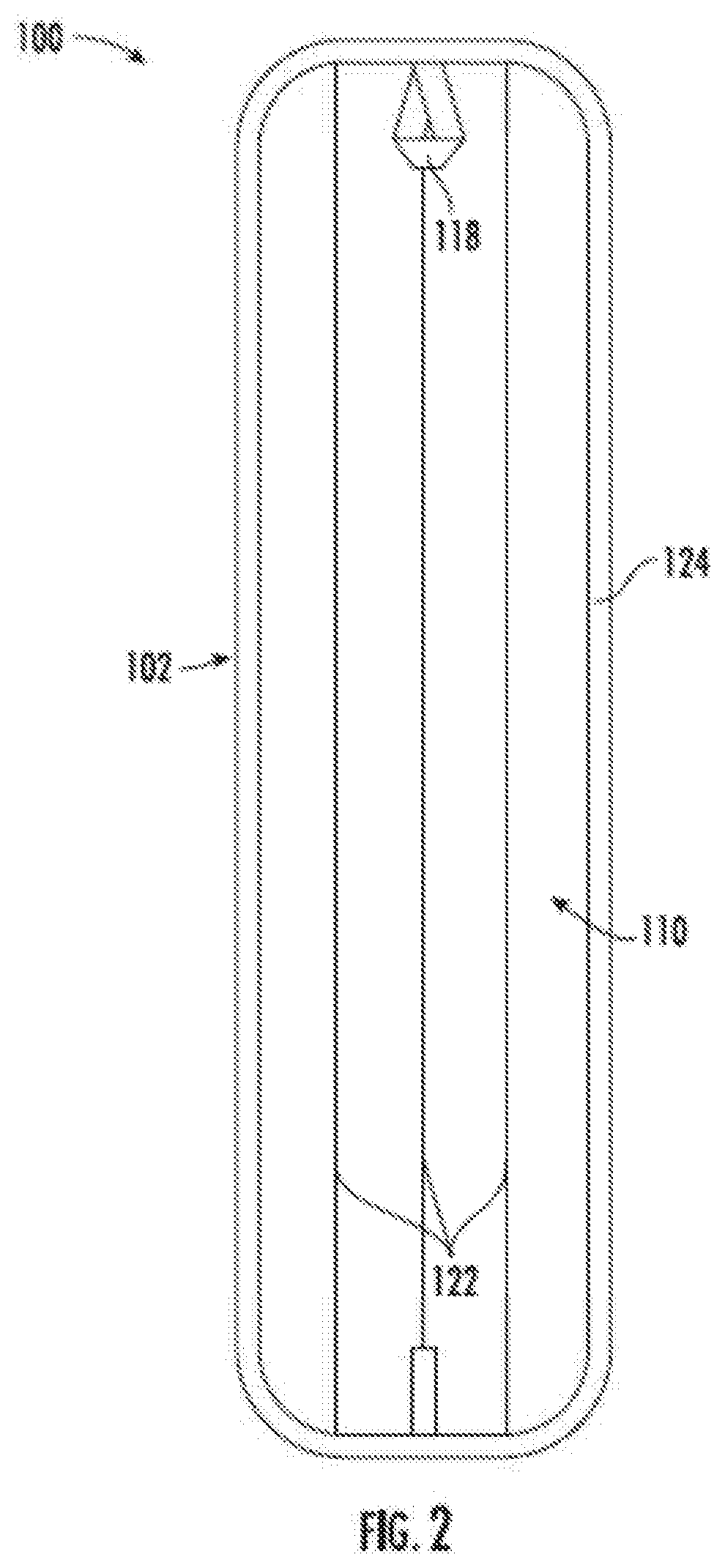
[0008] FIG. 2 is a plan view of the non-cleaning surface of the mop head of FIG. 1.
[0009] FIG. 3 is a side view of the mop head of FIG. 1.
[0010] FIG. 4 is a partial magnified cross-sectional view of the mop head of FIG. 1.
[0011] FIG. 5 is a perspective rear view of the mop head of FIG. 1.
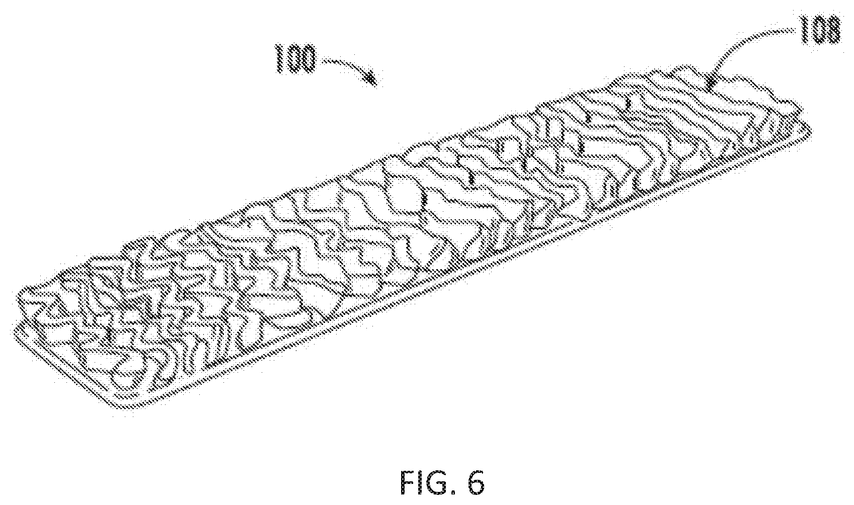
[0012] FIG. 6 is a perspective view of one embodiment of a mop head.
[0013] FIG. 7 is a perspective view, including a magnified portion, of the mop head of FIG. 6 in one embodiment of a mop assembly.
[0014] FIG. 8 is a front view of the cleaning side of one embodiment of a mop head.
[0015] FIG. 9 is a side perspective view of the mop head of FIG. 8.
DETAILED DESCRIPTION
[0016] The present disclosure provides mop assemblies and mop heads for use in such assemblies, for cleaning and collecting both large and small dust and debris particles, as well as liquids. The particular mop head designs described herein may help to gather larger particles typically missed by flat mops. Additionally, the body of the mop may be configured to easily empty over a trash receptacle and/or to be laundered.
[0017] In some embodiments, a mop head includes an elongated body with a length dimension that is greater than a width dimension, and has a cleaning side and an opposed backside. The cleaning side defines a surface that is configured to contact the floor or other surface or substrate, during a cleaning activity. The opposed backside defines a surface opposite the cleaning surface, which may be configured for coupling the mop head within a mop assembly (e.g., to an elongated handle of a mop assembly).
[0018] The mop head also includes a plurality of fabric ribs that define a plurality of channels therebetween on the cleaning side of the elongated body. The plurality of fabric ribs may be irregular in shape, as will be described in greater detail below, and the direction of the plurality of channels formed by the ribs may be parallel to either the length of the width direction of the mop. A layer of foam or fabric may be provided between the cleaning side and the opposed backside.
[0019] In some embodiments, as shown in FIG. 1, the mop head 100 includes a plurality of fabric ribs 112. For example, as discussed herein, the plurality of fabric ribs 112 may be shaped and sized to skim across a floor or other substrate to accumulate dirt, dust, debris, and liquids. In some instances, the plurality of fabric ribs 112 may be shaped, or formed, out of a woven, knitted, or nonwoven fabric. For example, the plurality of fabric ribs 112 may be rayon, polyester, nylon, microfiber, wool, cotton, or some combination thereof. For example, the fabric surface (e.g., a microfiber surface) may be configured to gather smaller particles by capturing the smaller particles within the fibers of the fabric, while the larger particles may be gathered by the structure of the channels (e.g., how the fabric ribs on the elongated body are formed). That is, the fabric in combination with the pattern and geometry of the ribs may improve debris gathering efficiency. In some instances, the plurality of fabric ribs 112 may be formed by more than one piece of fabric, whereas in other embodiments, the ribs 112 are formed of a continuous piece of fabric forming more than one of the ribs 112. The mop head 100 may be launderable, disposable, and/or configured for one-time use.
[0020] Channels 114 may be formed by the plurality of fabric ribs 112 and parallel to either the length direction of the mop. For example, the channels 114 may be formed by the plurality of fabric ribs 112 and may be parallel to the width direction of the mop. The channels 114 may be formed by the plurality of fabric ribs 112 and may capture larger dirt, dust, or debris particles.
[0021] In some embodiments, as shown in FIGS. 1-9, the plurality of fabric ribs 112 extend from the cleaning side 108 of the mop head 100. Any suitable method and design may be used to form the plurality of fabric ribs 112. For example, each fabric rib 112 may be formed of a single "ply" of fabric affixed to the cleaning side 108. That is, each rib 112 may be formed from a single piece of fabric having one edge attached at the cleaning side 108 and having the opposing edge define a free edge of the rib.
[0022] Alternatively, the plurality of fabric ribs 112 may be formed by one or more continuous pieces of fabric. The continuous fabric may be at least partially folded to form at least a single folded rib 126. That is, such continuous fabric ribs may involve at least a "two ply" construction, such that the fabric is affixed to at least two points on the cleaning side 108 to form a rib (e.g., the fold) protruding between the two attachment points. Once folded over to form a rib 126, the fabric may be sewn or otherwise attached in any suitable fashion to the body of the mop head to permanently define the rib 126. For example, the fabric may be sewn along the ribs to define the ribs and/or may be sewn in a direction perpindicular to the ribs to otherwise restrain the fabric. For example, lock and/or overlock stiching patterns may be used. In some instances, the plurality of fabric ribs may be secured by fasteners or other sewing patterns. The fabric ribs may be irregularly shaped.
[0023] As previously discussed, the rib 126 as a whole may be configured to capture smaller particles within the surface fibers of the material, and the body of the rib 126 may capture larger particles by an internal volume 130 defined by its size, shape and stitched configuration (e.g., a pocket-like volume formed by the rib), as shown in FIGS. 8 and 9. For example, the internal volume 130 may extend substantially along the length dimension 104 of the head to capture and channel any large particles within the internal volume 130 of the plurality of fabric ribs 112 through the mop head 100. In other instances, the internal volume 130 of the plurality of fabric ribs 112 may extend substantially along the width direction 106 of the head to gather large particles. The internal volume 130 may be formed by folding over the fabric and stitching the rib 126 in a length dimension 104 and/or a width dimension 106.
[0024] In some embodiments, a fabric rib 126 may be sewn onto the elongated body 102 such that it has a height of about three centimeters. As used herein, the term "about" refers to a range of +/-twenty percent of the unit of measurement stated thereafter. As used herein, the term "height" refers to the distance from the surface of the elongated body to the farthest edge of the named element (e.g., rib) from the elongated body. The plurality of fabric ribs 112 may each range in height from about 0.5 centimeter to about ten centimeters. For example, each of the plurality of fabric ribs 112 may each have a height of about 2.4 to about 3.6 centimeters.
[0025] In some embodiments, as shown in FIG. 1, the plurality of fabric ribs 112 may be sewn and extend substantially in the width direction 106. As used herein, the term "extend substantially" refers to a direction of an element along the elongated body 102 of the mop head 100 (i.e., extend substantially in the width dimension 106 of the elongated body 102 indicates that the named element runs mostly parallel with the elongated body's width dimension 106). In some embodiments, the plurality of fabric ribs 112 may extend substantially in the length dimension 104. In other embodiments, the plurality of fabric ribs 112 may extend in a variety of other directions, such as diagonally. In any of these embodiments, the plurality of fabric ribs 112 may be discontinuous along the elongated body 102.
[0026] In some embodiments, as shown in FIGS. 1, 3-5, and 8, the plurality of fabric ribs 112 define a plurality of channels 114 defined between the plurality of fabric ribs 112. For example, the plurality of fabric ribs 112 may extend substantially in a width dimension 106, and the plurality of channels 114 likewise may extend substantially parallel to the width dimension 106. In some instances, the plurality of channels 114 extend substantially in the length direction 104 or some other direction along the elongated body 102.
[0027] As shown in FIGS. 3 and 8, the plurality of channels 114 separate each rib 126 in the plurality of fabric ribs 112. In some instances, the plurality of channels 114 may be formed by fabric ribs that have a width of about three centimeters. The plurality of channels 114 may each range in width from about 0.2 centimeters to about ten centimeters. For example, the plurality of channels 114 may each have a width of about 2.4 centimeters to about 3.6 centimeters. In other embodiments, the plurality of channels 114 may extend discontinuously in the length dimension 104 or the width dimension 106.
[0028] In some embodiments, as shown in FIG. 1, the plurality of fabric ribs 112 cover a substantial portion of the elongated body 102. As used herein, the phrase "substantial portion" refers to the named element covering an area of at least 50% from one end to another end of the elongated body 102. For example, the plurality of fabric ribs 112 cover a substantial portion of the elongated body 102 in the length dimension 104. In other embodiments, the plurality of fabric ribs 112 cover a substantial portion of the elongated body 102 in the width dimension 106. In some embodiments, as shown in FIG. 1, the plurality of channels 114 cover a substantial portion of the elongated body 102 in the width dimension 104. In other embodiments, the plurality of channels 114 cover a substantial portion of the elongated body 102 in the length dimension 104. In some instances, the plurality of channels 114 and the plurality of ribs 112 do not cover a substantial portion of the elongated body 102 in either dimension.
[0029] In some instances, as shown in FIG. 1, the plurality of channels 114 are formed by stitching in the width dimension 106 of the elongated body 102. In some instances, lock stitching 122 may simultaneously form the plurality of channels 114 and plurality of fabric ribs 112. As used herein, the terms "lock stitching" refers to a single stitch that locks a top and bottom thread together to secure fabric. In some instances, overlock stitching may form the plurality of channels 114 and plurality of fabric ribs 112. As used herein, the terms "overlock stitching" refers to stitching that is formed by a straight stitch and a zigzag pattern. Lock stitching 122 and overlock stitching may both be used to form the plurality of channels 114 and plurality of ribs 112. In some embodiments, as shown in FIG. 1, lock stitching 122 extends substantially in the length dimension 104 and the width dimension 106.
[0030] Lock stitching 122 may be used for creating discontinuous fabric ribs 112 on the cleaning side 108 of the elongated body 102. Additionally, lock stitching 122 may be used for creating inconsistent heights for the plurality of fabric ribs 112. Further, lock stitching 122 may be used for creating inconsistent widths for the plurality of channels 114. In certain instances, the lock stitching 122 may be continuous from end to end of the elongated body 102.
[0031] In other instances, the plurality of channels 114 may be formed by adhesive, fasteners, or another type of stitching.
[0032] In certain embodiments, as shown in FIG. 1, the mop head 100 includes an elongated body 102. For example, the elongated body's 102 length dimension 104 may be greater than the width dimension 106. In some embodiments, the length dimension 104 may measure between about five centimeters long to about two meters long. In some embodiments, the elongated body's 102 width dimension 106 may measure between about five centimeters long to about two meters long.
[0033] In some embodiments, as shown in FIGS. 1 and 2, the mop head 100 includes at least two sides, a cleaning side 108 and an opposed backside 110. For example, the opposed backside 110 may be woven, knitted, or nonwoven fabric. For example, each side may be configured for a different purpose. For example, the cleaning side 108 may include a plurality of fabric ribs 112 and a plurality of channels 114 configured to accumulate dirt, dust, debris, and liquids, as discussed herein, whereas the opposed backside 110 may be configured to be coupled to a mop handle, attachment head 120, or another mechanism for sweeping floors (as depicted by FIG. 7). For example, the opposed backside 110 may be attached to the mop head 100 with hook and loop attachment. The cleaning side 108 may be the side of the mop head 100 configured to contact the floor to pick up the aforementioned dirt, dust, debris, and liquids.
[0034] In some embodiments, as seen in FIGS. 4 and 5, the mop head 100 includes a binding material 124 configured to bind the cleaning side 108 to the opposed back side 110. For example, the binding material 124 may be an adhesive material (e.g., tape) or a strip of fabric (e.g., polyester) sewn around the perimeter of the mop head 100. In some instances, the binding material 124 may be another material, such as wool, cotton, spandex, polyester, nylon or some other knitted, woven, or nonwoven cloth.
[0035] In some embodiments, as shown in FIG. 5, the mop head 100 includes a hang loop 118 coupled to the binding material 124 on the opposed backside 110. For example, the hang loop 118 may be made of the same fabric as the binding material 124 coupled to the edges of the mop head 100. In some embodiments, the mop head 100 may include multiple hang loops 118 on the binding material 124 or another location on the mop head 100. For example, the hang loop 118 may be configured to facilitate connection of the mop head 100 to a mop assembly, such as via an attachment head 120 (shown in FIG. 7) or to facilitate hanging storage of the mop head.
[0036] In certain embodiments, as shown in FIG. 4, a layer of foam or fabric 116 is disposed between the cleaning side 108 and the opposed backside 110. In some instances, the layer of foam or fabric 116 may be disposed on or form the cleaning side 108 of the mop head 100. For example, the layer of foam or fabric 116 may be attached to the cleaning side 108 of the mop head 100, such that the ribs 112 extend from the foam or fabric. In some instances, the layer of foam or fabric 116 may be disposed on or form the opposed backside 110. For example, the layer of foam or fabric 116 may be attached to the opposed backside 110 of the mop head 100. In some embodiments, the layer of foam or fabric 116 may form both surfaces of the cleaning side 108 and the opposed backside 110.
[0037] For example, the layer of foam 116 may be made of an absorbent material, such as a polyurethane, polyethylene, sponge, or another material configured to absorb liquids within the mop head. The layer of foam 116 may be configured to absorb liquids through the cleaning side 108 or the opposed backside 110. The layer of foam 116 may be configured to release liquids when squeezed, flattened, or have some other pressure act on the layer of foam 116.
[0038] In some embodiments, as shown in FIG. 7, the mop head 100 may be configured to operably attach to the attachment head 120 of a mop assembly 132 by any suitable attachment means known in the industry (e.g., hook and loop attachment, other mechanical attachment). In some embodiments, the mop head 100 may selectively attach to the attachment head 120 via a mechanical fastener, adhesive, or some combination therein.
[0039] In some instances, the attachment head 120 is a solid plastic or metal component configured to secure the mop head 100 thereto for cleaning a surface. In some embodiments, the attachment head 120 attaches to the mop assembly 132 that includes a shaft and, optionally a yoke, for maneuvering the mop assembly during cleaning. For example, the mop assembly 132 may include an elongated mop handle operable for a user to control the path of the attachment head 120. For example, a yoke may be attached to the shaft and/or the mop handle. The yoke may be configured to rotate the attachment head 120 in a plurality of angles and directions. The mop head 100 may be operably coupled to the mop handle via the attachment head 120.
[0040] While the disclosure has been described with reference to a number of embodiments, it will be understood by those skilled in the art that the disclosure is not limited to such disclosed embodiments. Rather, the disclosed embodiments can be modified to incorporate any number of variations, alterations, substitutions, or equivalent arrangements not described herein, but which are commensurate with the scope of the disclosure.
* * * * *
D00000
D00001
D00002
D00003
D00004
D00005
D00006
D00007
D00008
D00009
XML
uspto.report is an independent third-party trademark research tool that is not affiliated, endorsed, or sponsored by the United States Patent and Trademark Office (USPTO) or any other governmental organization. The information provided by uspto.report is based on publicly available data at the time of writing and is intended for informational purposes only.
While we strive to provide accurate and up-to-date information, we do not guarantee the accuracy, completeness, reliability, or suitability of the information displayed on this site. The use of this site is at your own risk. Any reliance you place on such information is therefore strictly at your own risk.
All official trademark data, including owner information, should be verified by visiting the official USPTO website at www.uspto.gov. This site is not intended to replace professional legal advice and should not be used as a substitute for consulting with a legal professional who is knowledgeable about trademark law.