Vacuum Cleaner
Moeller; Scott T.
U.S. patent application number 16/445514 was filed with the patent office on 2020-01-02 for vacuum cleaner. The applicant listed for this patent is MILWAUKEE ELECTRIC TOOL CORPORATION. Invention is credited to Scott T. Moeller.
| Application Number | 20200000300 16/445514 |
| Document ID | / |
| Family ID | 68840644 |
| Filed Date | 2020-01-02 |


View All Diagrams
| United States Patent Application | 20200000300 |
| Kind Code | A1 |
| Moeller; Scott T. | January 2, 2020 |
VACUUM CLEANER
Abstract
A vacuum cleaner station is configured to operate with first and second power tools, each power tool having an electrical plug. The vacuum cleaner station includes a housing, a suction source, a first hose port, a first valve, a first hose, a second hose port, a second valve, a second hose, a debris collection chamber, a battery receptacle, a battery pack receivable in the battery receptacle, a first electrical outlet on the housing, a first sensor configured to detect when the first power tool is receiving power from the battery pack, a second electrical outlet on the housing, a second sensor configured to detect when the second power tool is receiving power from the battery pack, and a controller electrically coupled to the suction source, the first sensor, the second sensor, the first valve, and the second valve.
| Inventors: | Moeller; Scott T.; (Richfield, WI) | ||||||||||
| Applicant: |
|
||||||||||
|---|---|---|---|---|---|---|---|---|---|---|---|
| Family ID: | 68840644 | ||||||||||
| Appl. No.: | 16/445514 | ||||||||||
| Filed: | June 19, 2019 |
Related U.S. Patent Documents
| Application Number | Filing Date | Patent Number | ||
|---|---|---|---|---|
| 62764878 | Aug 16, 2018 | |||
| 62687090 | Jun 19, 2018 | |||
| Current U.S. Class: | 1/1 |
| Current CPC Class: | A47L 5/36 20130101; A47L 9/248 20130101; A47L 7/0095 20130101; A47L 5/24 20130101; A47L 9/0036 20130101; A47L 9/2857 20130101; A47L 9/009 20130101; A47L 9/322 20130101; A47L 9/2884 20130101; A47L 9/1409 20130101; A47L 5/225 20130101; A47L 9/122 20130101 |
| International Class: | A47L 7/00 20060101 A47L007/00 |
Claims
1. A vacuum cleaner station configured to operate with first and second power tools, each power tool having an electrical plug, the vacuum cleaner station comprising: a housing; a suction source supported by the housing; a first hose port on the housing and fluidly coupled to the suction source; a first valve moveable between an open position, in which the first hose port is open, and a closed position, in which the first hose port is blocked; a first hose selectively connected to the first hose port, the first hose configured to extend to the first power tool, such that when the first valve is in the open position and the suction source is actuated, debris generated during operation of the first power tool can be suctioned through the first hose into the first hose port; a second hose port on the housing and fluidly coupled to the suction source; a second valve moveable between an open position, in which the second hose port is open, and a closed position, in which the second hose port is blocked; a second hose selectively connected to the second hose port, the second hose configured to extend to the second power tool, such that when the second valve is in the open position and the suction source is actuated, debris generated during operation of the second power tool can be suctioned through the second hose into the second hose port; a debris collection chamber configured to receive debris suctioned by the suction source through the first hose port and the second hose port; a battery receptacle on the housing; a battery pack receivable in the battery receptacle, such that when the battery pack is received in the battery receptacle, the battery pack provides power to the suction source; a first electrical outlet on the housing, the first electrical outlet configured to receive the electrical plug of the first power tool, such that when the electrical plug of the first power tool is received in the first electrical outlet, the battery pack is received in the battery receptacle, and the first power tool is turned on, the battery pack provides power to the first power tool; a first sensor configured to detect when the first power tool is receiving power from the battery pack; a second electrical outlet on the housing, the second electrical outlet configured to receive the electrical plug of the second power tool, such that when the electrical plug of the second power tool is received in the second electrical outlet, the battery pack is received in the battery receptacle, and the second power tool is turned on, the battery pack provides power to the second power tool; a second sensor configured to detect when the second power tool is receiving power from the battery pack; and a controller electrically coupled to the suction source, the first sensor, the second sensor, the first valve, and the second valve, wherein in response to the first sensor detecting that the first power tool is receiving power from the battery pack, the controller is configured to move the first valve to the open position and actuate the suction source to suction debris through the first hose, the first hose port and into the debris collection chamber, and wherein in response to the second sensor detecting that the second power tool is receiving power from the battery pack, the controller is configured to move the second valve to the open position and actuate the suction source to suction debris through the second hose, the second hose port and into the debris collection chamber.
2. The vacuum cleaner station of claim 1, wherein the vacuum cleaner station is in wireless communication with the first and second power tools.
3. The vacuum cleaner station of claim 1, further comprising a cyclonic separator arranged fluidly between the first hose port and the debris collection chamber, and arranged fluidly between the second hose port and the debris collection chamber.
4. The vacuum cleaner station of claim 1, wherein the battery receptacle is a first battery receptacle and the battery pack is a first battery pack, wherein the vacuum cleaner station further comprises a second battery receptacle on the housing and a second battery pack receivable in the second battery receptacle, and wherein when the second battery pack is received in the second battery receptacle, the second battery pack is configured to provide power to the suction source, the first electrical outlet and the second electrical outlet.
5. The vacuum cleaner station of claim 1, further comprising a plurality of wheels, a handle, and a storage compartment.
6. The vacuum cleaner station of claim 5, further comprising a first indicator switchable between a first state that indicates the first power tool is receiving power from the battery pack and a second state that indicates the first power tool is not receiving power from the battery pack, the second state being different from the first state, wherein in response to the first sensor detecting that the first power tool is receiving power from the battery pack, the controller is configured to set the first indicator to the first state.
7. The vacuum cleaner station of claim 6, further comprising a second indicator switchable between a first state that indicates the second power tool is receiving power from the battery pack and a second state that indicates the second power tool is not receiving power from the battery pack, the second state being different from the first state, wherein in response to the second sensor detecting that the second power tool is receiving power from the battery pack, the controller is configured to set the second indicator to the first state.
8. A vacuum cleaner station configured to operate with a first power tool configured to send a wireless first tool signal when the first power tool is operating and a second power tool configured to send a wireless second tool signal when the second power tool is operating, the vacuum cleaner station comprising: a housing; a suction source supported by the housing; a first hose port on the housing and fluidly coupled to the suction source; a first valve moveable between an open position, in which the first hose port is open, and a closed position, in which the first hose port is blocked; a first hose selectively connected to the first hose port, the first hose configured to extend to the first power tool, such that when the first valve is in the open position and the suction source is actuated, debris generated during operation of the first power tool can be suctioned through the first hose into the first hose port; a second hose port on the housing and fluidly coupled to the suction source; a second valve moveable between an open position, in which the second hose port is open, and a closed position, in which the second hose port is blocked; a second hose selectively connected to the second hose port, the second hose configured to extend to the second power tool, such that when the second valve is in the open position and the suction source is actuated, debris generated during operation of the second power tool can be suctioned through the second hose into the second hose port; a debris collection chamber configured to receive debris suctioned by the suction source through the first hose port and the second hose port; a battery receptacle on the housing; a battery pack receivable in the battery receptacle, such that when the battery pack is received in the battery receptacle, the battery pack provides power to the suction source; a wireless communication unit configured to receive the wireless first tool signal from the first power tool when the first power tool is operating and configured to receive the wireless second tool signal from the second power tool when the second power tool is operating; and a controller electrically coupled to the suction source, the wireless communication unit, the first valve, and the second valve, wherein in response to the wireless communication unit receiving the wireless first tool signal, the controller is configured to move the first valve to the open position and actuate the suction source to suction debris through the first hose, the first hose port and into the debris collection chamber, and wherein in response to the wireless communication unit receiving the wireless second tool signal, the controller is configured to move the second valve to the open position and actuate the suction source to suction debris through the second hose, the second hose port and into the debris collection chamber.
9. The vacuum cleaner station of claim 8, wherein the wireless communication unit is a transceiver.
10. The vacuum cleaner station of claim 8, wherein the wireless communication unit is a receiver.
11. The vacuum cleaner station of claim 8, further comprising a first indicator that is switchable between a first state that indicates the wireless first tool signal is being received by the wireless communication unit, and a second state that indicates the wireless first tool signal is not being received by the wireless communication unit, the second state being different from the first state.
12. The vacuum cleaner station of claim 11, further comprising a second indicator that is switchable between a first state that indicates the wireless second tool signal is being received by the wireless communication unit, and a second state that indicates the wireless second tool signal is not being received by the wireless communication unit, the second state being different from the first state.
13. The vacuum cleaner station of claim 8, further comprising a cyclonic separator arranged fluidly between the first hose port and the debris collection chamber, and arranged fluidly between the second hose port and the debris collection chamber.
14. The vacuum cleaner station of claim 8, wherein the battery receptacle is a first battery receptacle and the battery pack is a first battery pack, wherein the vacuum cleaner station further comprises a second battery receptacle on the housing and a second battery pack receivable in the second battery receptacle, and wherein when the second battery pack is received in the second battery receptacle, the second battery pack is configured to provide power to the suction source.
15. A vacuum cleaner station configured to operate with a power tool that is configured to send a wireless tool signal when the power tool is operating, the vacuum cleaner station comprising: a housing; a suction source supported by the housing; a hose port on the housing and fluidly coupled to the suction source; a hose selectively connected to the hose port, the hose configured to extend to the power tool, such that debris generated during operation of the power tool can be suctioned through the hose into the hose port; a debris collection chamber configured to receive debris suctioned by the suction source through the hose port; a battery receptacle on the housing; a battery pack receivable in the battery receptacle, such that when the battery pack is received in the battery receptacle, the battery pack provides power to the suction source; a wireless communication unit configured to receive the wireless tool signal from the power tool when the first power tool is operating; and a controller electrically coupled to the suction source and the wireless communication unit, wherein in response to the wireless communication unit receiving the wireless first tool signal, the controller is configured actuate the suction source to suction debris through the hose, the hose port and into the debris collection chamber.
16. The vacuum cleaner station of claim 15, wherein the wireless communication unit is a transceiver.
17. The vacuum cleaner station of claim 15, wherein the wireless communication unit is a receiver.
18. The vacuum cleaner station of claim 15, further comprising a cyclonic separator arranged fluidly between the hose port and the debris collection chamber.
19. The vacuum cleaner station of claim 15, wherein the battery receptacle is a first battery receptacle and the battery pack is a first battery pack, wherein the vacuum cleaner station further comprises a second battery receptacle on the housing and a second battery pack receivable in the second battery receptacle, and wherein when the second battery pack is received in the second battery receptacle, the second battery pack is configured to provide power to the suction source.
20. The vacuum cleaner station of claim 15, further comprising a plurality of wheels, a handle, and a storage compartment.
21. A vacuum cleaner station configured to operate with a power tool having an electrical plug, the vacuum cleaner station comprising: a housing; a suction source supported by the housing; a hose port on the housing and fluidly coupled to the suction source; a hose selectively connected to the hose port, the hose configured to extend to the power tool, such that debris generated during operation of the power tool can be suctioned through the hose into the hose port; a debris collection chamber configured to receive debris suctioned by the suction source through the hose port; a battery receptacle on the housing; a battery pack receivable in the battery receptacle, such that when the battery pack is received in the battery receptacle, the battery pack provides power to the suction source; an electrical outlet on the housing, the electrical outlet configured to receive the electrical plug of the power tool, such that when the electrical plug of the power tool is received in the electrical outlet and the battery pack is received in the battery receptacle, the battery pack is configured to provide power to the power tool; a sensor configured to detect when the power tool is receiving power from the battery pack; and a controller electrically coupled to the suction source and the sensor, wherein in response to the sensor detecting that the power tool is receiving power from the battery pack, the controller is configured actuate the suction source to suction debris through the hose, the hose port and into the debris collection chamber.
22. The vacuum cleaner station of claim 21, wherein the vacuum cleaner station is in wireless communication with the power tool.
23. The vacuum cleaner station of claim 21, further comprising a cyclonic separator arranged fluidly between the hose port and the debris collection chamber.
24. The vacuum cleaner station of claim 21, wherein the battery receptacle is a first battery receptacle and the battery pack is a first battery pack, wherein the vacuum cleaner station further comprises a second battery receptacle on the housing and a second battery pack receivable in the second battery receptacle, and wherein when the second battery pack is received in the second battery receptacle, the second battery pack is configured to provide power to the suction source, the first electrical outlet and the second electrical outlet.
25. The vacuum cleaner station of claim 21, further a valve moveable between an open position, in which the hose port is open, and a closed position, in which the hose port is blocked, and wherein in response to the sensor detecting that the power tool is receiving power from the battery pack, the controller is configured to move the valve to the open position.
26. The vacuum cleaner station of claim 21, further an indicator configured to indicate when the power tool is receiving power from the battery pack.
27. The vacuum cleaner of claim 26, wherein the indicator is switchable between a first state that indicates the power tool is receiving power from the battery pack and a second state that indicates the power tool is not receiving power from the battery pack, the second state being different from the first state, wherein in response to the sensor detecting that the power tool is receiving power from the battery pack, the controller is configured to set the indicator to the first state.
28. The vacuum cleaner station of claim 21, further comprising: a storage compartment in the housing and a lid to selectively open and close the storage compartment; and a drawer that is selectively removable from the housing, the drawer containing the debris collection chamber.
29. A vacuum cleaner station configured to operate with first and second power tools, each power tool having an electrical plug, the vacuum cleaner station comprising: a housing; a suction source supported by the housing; a first hose port on the housing and fluidly coupled to the suction source; a first hose selectively connected to the first hose port, the first hose configured to extend to the first power tool, such that debris generated during operation of the first power tool can be suctioned through the first hose into the first hose port; a second hose port on the housing and fluidly coupled to the suction source; a second hose selectively connected to the second hose port, the second hose configured to extend to the second power tool, such that debris generated during operation of the second power tool can be suctioned through the second hose into the second hose port; a debris collection chamber configured to receive debris suctioned by the suction source through the first hose port and the second hose port; a battery receptacle on the housing; a battery pack receivable in the battery receptacle, such that when the battery pack is received in the battery receptacle, the battery pack provides power to the suction source; a first electrical outlet on the housing, the first electrical outlet configured to receive the electrical plug of the first power tool, such that when the electrical plug of the first power tool is received in the first electrical outlet and the battery pack is received in the battery receptacle, the battery pack is configured to provide power to the first power tool; and a second electrical outlet on the housing, the second electrical outlet configured to receive the electrical plug of the second power tool, such that when the electrical plug of the second power tool is received in the second electrical outlet and the battery pack is received in the battery receptacle, the battery pack is configured to provide power to the second power tool.
30. The vacuum cleaner station of claim 29, wherein the vacuum cleaner station is in wireless communication with the power tool.
31. The vacuum cleaner station of claim 29, further comprising a plurality of wheels and a telescoping handle.
32. The vacuum cleaner station of claim 31, further comprising a storage compartment in the housing and a lid to selectively open and close the storage compartment.
33. The vacuum cleaner station of claim 32, further comprising a drawer that is selectively removable from the housing, the drawer containing the debris collection chamber.
Description
CROSS-REFERENCE TO RELATED APPLICATIONS
[0001] This application claims priority to co-pending U.S. Provisional Patent Application No. 62/687,090 filed on Jun. 19, 2018, and co-pending Provisional Patent Application No. 62/764,878 filed on Aug. 16, 2018, and the entire contents of both Provisional Applications are incorporated herein by reference.
FIELD OF THE INVENTION
[0002] The present invention relates to vacuum cleaners, and more particularly to portable vacuum-out arrangements.
BACKGROUND OF THE INVENTION
[0003] On job sites, operators use vacuum cleaners to clean up dust and debris. Operators also use AC power sources to power cutting, sawing, and drilling tools.
SUMMARY OF THE INVENTION
[0004] The present invention provides, in one aspect, a vacuum cleaner station configured to operate with first and second power tools, each power tool having an electrical plug. The vacuum cleaner station comprises a housing, a suction source supported by the housing, a first hose port on the housing and fluidly coupled to the suction source, and a first valve moveable between an open position, in which the first hose port is open, and a closed position, in which the first hose port is blocked. The vacuum cleaner station further comprises a first hose selectively connected to the first hose port. The first hose is configured to extend to the first power tool, such that when the first valve is in the open position and the suction source is actuated, debris generated during operation of the first power tool can be suctioned through the first hose into the first hose port. The vacuum cleaner station further comprises a second hose port on the housing and fluidly coupled to the suction source and a second valve moveable between an open position, in which the second hose port is open, and a closed position, in which the second hose port is blocked. The vacuum cleaner station further comprises a second hose selectively connected to the second hose port, the second hose configured to extend to the second power tool, such that when the second valve is in the open position and the suction source is actuated, debris generated during operation of the second power tool can be suctioned through the second hose into the second hose port. The vacuum cleaner station further comprises a debris collection chamber configured to receive debris suctioned by the suction source through the first hose port and the second hose port, a battery receptacle on the housing, and a battery pack receivable in the battery receptacle, such that when the battery pack is received in the battery receptacle, the battery pack provides power to the suction source. The vacuum cleaner station further comprises a first electrical outlet on the housing. The first electrical outlet is configured to receive the electrical plug of the first power tool, such that when the electrical plug of the first power tool is received in the first electrical outlet, the battery pack is received in the battery receptacle, and the first power tool is turned on, the battery pack provides power to the first power tool. The vacuum cleaner station further comprises a first sensor configured to detect when the first power tool is receiving power from the battery pack and a second electrical outlet on the housing. The second electrical outlet is configured to receive the electrical plug of the second power tool, such that when the electrical plug of the second power tool is received in the second electrical outlet, the battery pack is received in the battery receptacle, and the second power tool is turned on, the battery pack provides power to the second power tool. The vacuum cleaner station further comprises a second sensor configured to detect when the second power tool is receiving power from the battery pack, and a controller electrically coupled to the suction source, the first sensor, the second sensor, the first valve, and the second valve. In response to the first sensor detecting that the first power tool is receiving power from the battery pack, the controller is configured to move the first valve to the open position and actuate the suction source to suction debris through the first hose, the first hose port and into the debris collection chamber. In response to the second sensor detecting that the second power tool is receiving power from the battery pack, the controller is configured to move the second valve to the open position and actuate the suction source to suction debris through the second hose, the second hose port and into the debris collection chamber.
[0005] The present invention provides, in another aspect, a vacuum cleaner station configured to operate with a first power tool configured to send a wireless first tool signal when the first power tool is operating and a second power tool configured to send a wireless second tool signal when the second power tool is operating. The vacuum cleaner station comprises a housing, a suction source supported by the housing, a first hose port on the housing and fluidly coupled to the suction source, and a first valve moveable between an open position, in which the first hose port is open, and a closed position, in which the first hose port is blocked. The vacuum cleaner station further comprises a first hose selectively connected to the first hose port. The first hose is configured to extend to the first power tool, such that when the first valve is in the open position and the suction source is actuated, debris generated during operation of the first power tool can be suctioned through the first hose into the first hose port. The vacuum cleaner station further comprises a second hose port on the housing and fluidly coupled to the suction source, and a second valve moveable between an open position, in which the second hose port is open, and a closed position, in which the second hose port is blocked. The vacuum cleaner station further comprises a second hose selectively connected to the second hose port. The second hose is configured to extend to the second power tool, such that when the second valve is in the open position and the suction source is actuated, debris generated during operation of the second power tool can be suctioned through the second hose into the second hose port. The vacuum cleaner station further comprises a debris collection chamber configured to receive debris suctioned by the suction source through the first hose port and the second hose port, a battery receptacle on the housing, and a battery pack receivable in the battery receptacle, such that when the battery pack is received in the battery receptacle, the battery pack provides power to the suction source. The vacuum cleaner station further comprises a wireless communication unit configured to receive the wireless first tool signal from the first power tool when the first power tool is operating and configured to receive the wireless second tool signal from the second power tool when the second power tool is operating. The vacuum cleaner station further comprises a controller electrically coupled to the suction source, the wireless communication unit, the first valve, and the second valve. In response to the wireless communication unit receiving the wireless first tool signal, the controller is configured to move the first valve to the open position and actuate the suction source to suction debris through the first hose, the first hose port and into the debris collection chamber. In response to the wireless communication unit receiving the wireless second tool signal, the controller is configured to move the second valve to the open position and actuate the suction source to suction debris through the second hose, the second hose port and into the debris collection chamber.
[0006] The present invention provides, in yet another aspect, a vacuum cleaner station configured to operate with a power tool that is configured to send a wireless tool signal when the power tool is operating. The vacuum cleaner station comprises a housing, a suction source supported by the housing, a hose port on the housing and fluidly coupled to the suction source, and a hose selectively connected to the hose port. The hose is configured to extend to the power tool, such that debris generated during operation of the power tool can be suctioned through the hose into the hose port. The vacuum cleaner station further comprises a debris collection chamber configured to receive debris suctioned by the suction source through the hose port, a battery receptacle on the housing, and a battery pack receivable in the battery receptacle, such that when the battery pack is received in the battery receptacle, the battery pack provides power to the suction source. The vacuum cleaner station further comprises a wireless communication unit configured to receive the wireless tool signal from the power tool when the first power tool is operating, and a controller electrically coupled to the suction source and the wireless communication unit. In response to the wireless communication unit receiving the wireless first tool signal, the controller is configured actuate the suction source to suction debris through the hose, the hose port and into the debris collection chamber.
[0007] The present invention provides, in yet another aspect, a vacuum cleaner station configured to operate with a power tool having an electrical plug. The vacuum cleaner station comprises a housing, a suction source supported by the housing, a hose port on the housing and fluidly coupled to the suction source, and a hose selectively connected to the hose port. The hose is configured to extend to the power tool, such that debris generated during operation of the power tool can be suctioned through the hose into the hose port. The vacuum cleaner station further comprises a debris collection chamber configured to receive debris suctioned by the suction source through the hose port, a battery receptacle on the housing, and a battery pack receivable in the battery receptacle, such that when the battery pack is received in the battery receptacle, the battery pack provides power to the suction source. The vacuum cleaner station further comprises an electrical outlet on the housing. The electrical outlet is configured to receive the electrical plug of the power tool, such that when the electrical plug of the power tool is received in the electrical outlet and the battery pack is received in the battery receptacle, the battery pack is configured to provide power to the power tool. The vacuum cleaner station further comprises a sensor configured to detect when the power tool is receiving power from the battery pack and a controller electrically coupled to the suction source and the sensor. In response to the sensor detecting that the power tool is receiving power from the battery pack, the controller is configured actuate the suction source to suction debris through the hose, the hose port and into the debris collection chamber.
[0008] The present invention provides, in yet another aspect, a vacuum cleaner station cleaner station configured to operate with first and second power tools, each power tool having an electrical plug. The vacuum cleaner station comprises a housing, a suction source supported by the housing, a first hose port on the housing and fluidly coupled to the suction source, and a first hose selectively connected to the first hose port. The first hose is configured to extend to the first power tool, such that debris generated during operation of the first power tool can be suctioned through the first hose into the first hose port. The vacuum cleaner station further comprises a second hose port on the housing and fluidly coupled to the suction source and a second hose selectively connected to the second hose port. The second hose is configured to extend to the second power tool, such that debris generated during operation of the second power tool can be suctioned through the second hose into the second hose port. The vacuum cleaner station further comprises a debris collection chamber configured to receive debris suctioned by the suction source through the first hose port and the second hose port, a battery receptacle on the housing, and a battery pack receivable in the battery receptacle, such that when the battery pack is received in the battery receptacle, the battery pack provides power to the suction source. The vacuum cleaner station further comprises a first electrical outlet on the housing. The first electrical outlet is configured to receive the electrical plug of the first power tool, such that when the electrical plug of the first power tool is received in the first electrical outlet and the battery pack is received in the battery receptacle, the battery pack is configured to provide power to the first power tool. The vacuum cleaner station further comprises a second electrical outlet on the housing. The second electrical outlet is configured to receive the electrical plug of the second power tool, such that when the electrical plug of the second power tool is received in the second electrical outlet and the battery pack is received in the battery receptacle, the battery pack is configured to provide power to the second power tool.
[0009] The present invention provides, in yet another aspect, a vacuum cleaner comprising a first portion including a nozzle defining a first axis and a debris collection chamber defining a second axis. The vacuum cleaner further comprises a second portion including a handle, a motor defining a third axis, a fan driven by the motor, a filter defining a fourth axis, and a battery for providing power to the motor. The first portion is removably coupled to the second portion, and the first, second, third and fourth axes are coaxial when the first portion is coupled to the second portion.
[0010] The present invention provides, in yet another aspect, a vacuum cleaner comprising a nozzle, a debris collection chamber, a handle, a motor defining a motor axis, a fan driven by the motor, a filter, and a battery pack for providing power to the motor. The motor is arranged in between the handle and the battery pack along a first axis that is perpendicular to the motor axis.
[0011] The present invention provides, in yet another aspect, a vacuum cleaner assembly comprising a first vacuum cleaner including a housing having a plurality of wheels, a debris collection chamber, a suction source arranged in the housing, and a power cord configured to be coupled to an AC power source such that when the power cord is coupled to the AC power source, the power cord can transmit power to the suction source. The first vacuum cleaner further includes a lid removably coupled to the housing. The lid includes a handle and a hose port that is fluidly coupled to the suction source when the lid is coupled to the housing. The vacuum cleaner assembly further comprises a second vacuum cleaner configured to be docked on the first vacuum cleaner and to receive a charge therefrom.
[0012] Other features and aspects of the invention will become apparent by consideration of the following detailed description and accompanying drawings.
BRIEF DESCRIPTION OF THE DRAWINGS
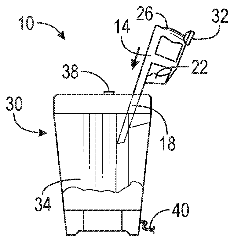
[0013] FIG. 1A is a perspective view of a stick station with a vacuum cleaner docked therein.
[0014] FIG. 1B is a cross-sectional view of the stick station of FIG. 1A, with the vacuum cleaner of FIG. 1A being inserted therein.
[0015] FIG. 1C is a cross-sectional view of the stick station of FIG. 1A, with the vacuum cleaner of FIG. 1A docked therein.
[0016] FIG. 1D is a cross-sectional view of the stick station of FIG. 1A, with the vacuum cleaner of FIG. 1A emptying debris therein.
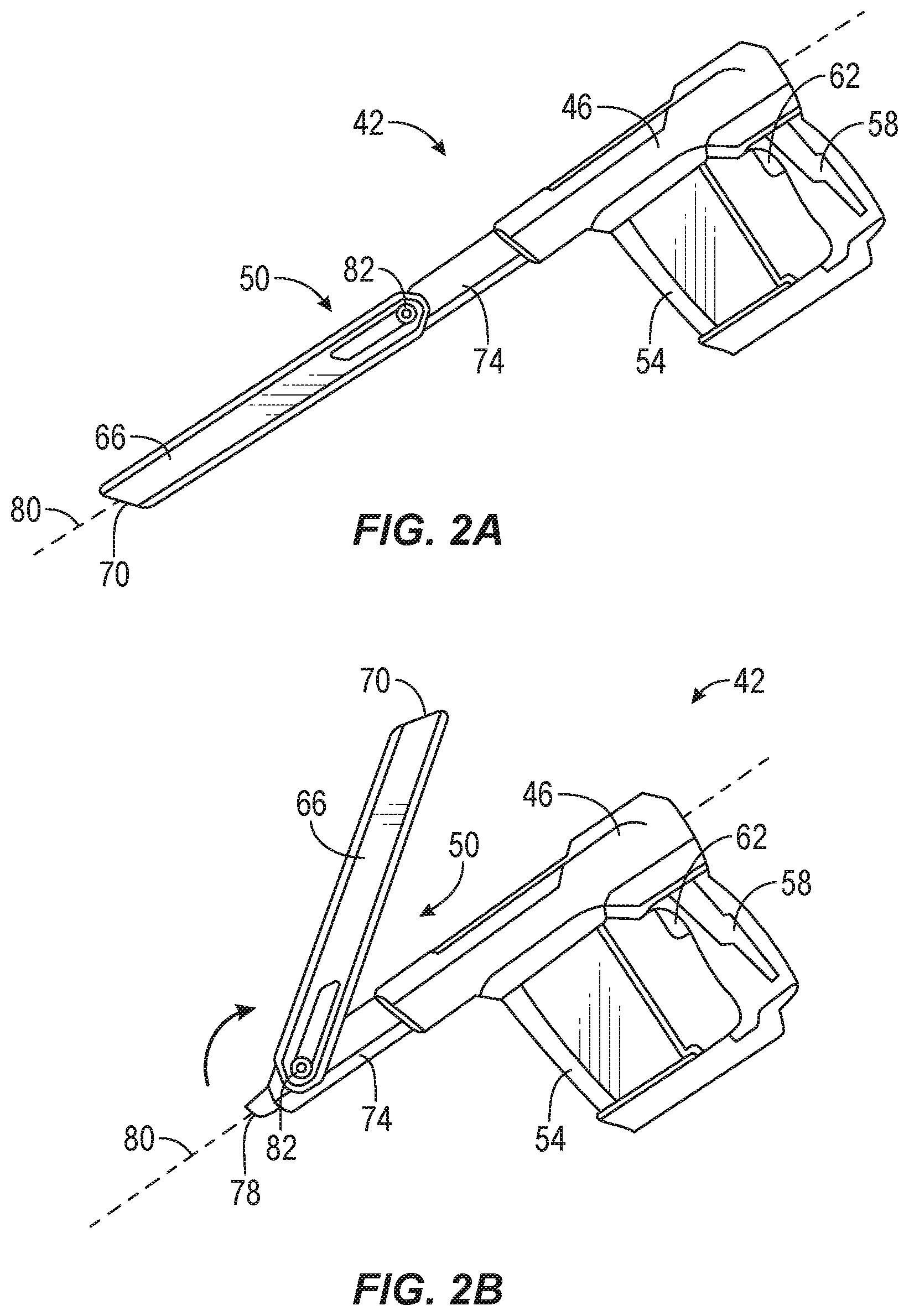
[0017] FIG. 2A is a plan view of a vacuum cleaner according to another embodiment of the invention, with a nose in a first position.
[0018] FIG. 2B is a plan view of the vacuum cleaner of FIG. 2A, with the nose in a second position.
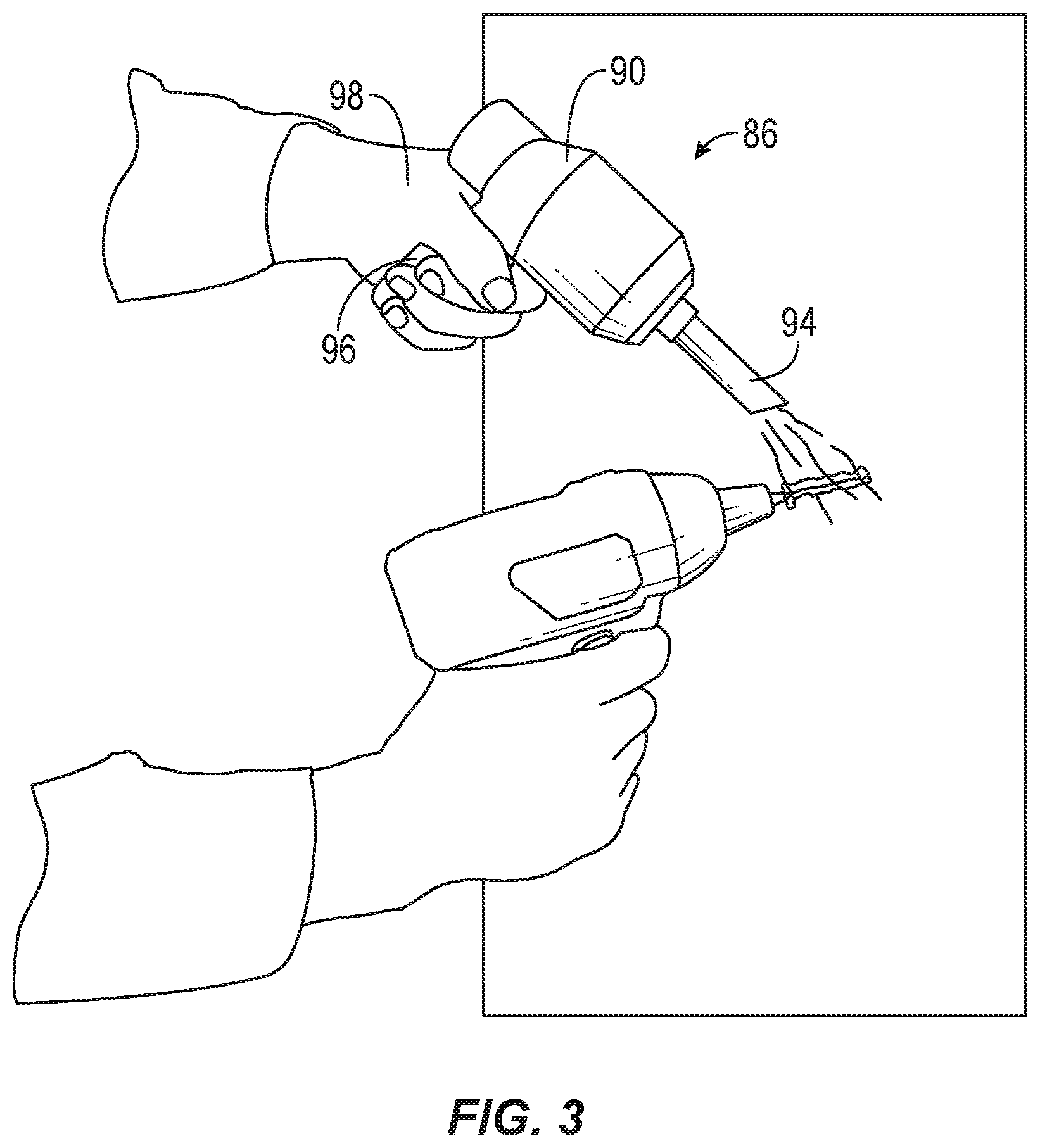
[0019] FIG. 3 is a perspective view of a vacuum cleaner according to another embodiment of the invention.
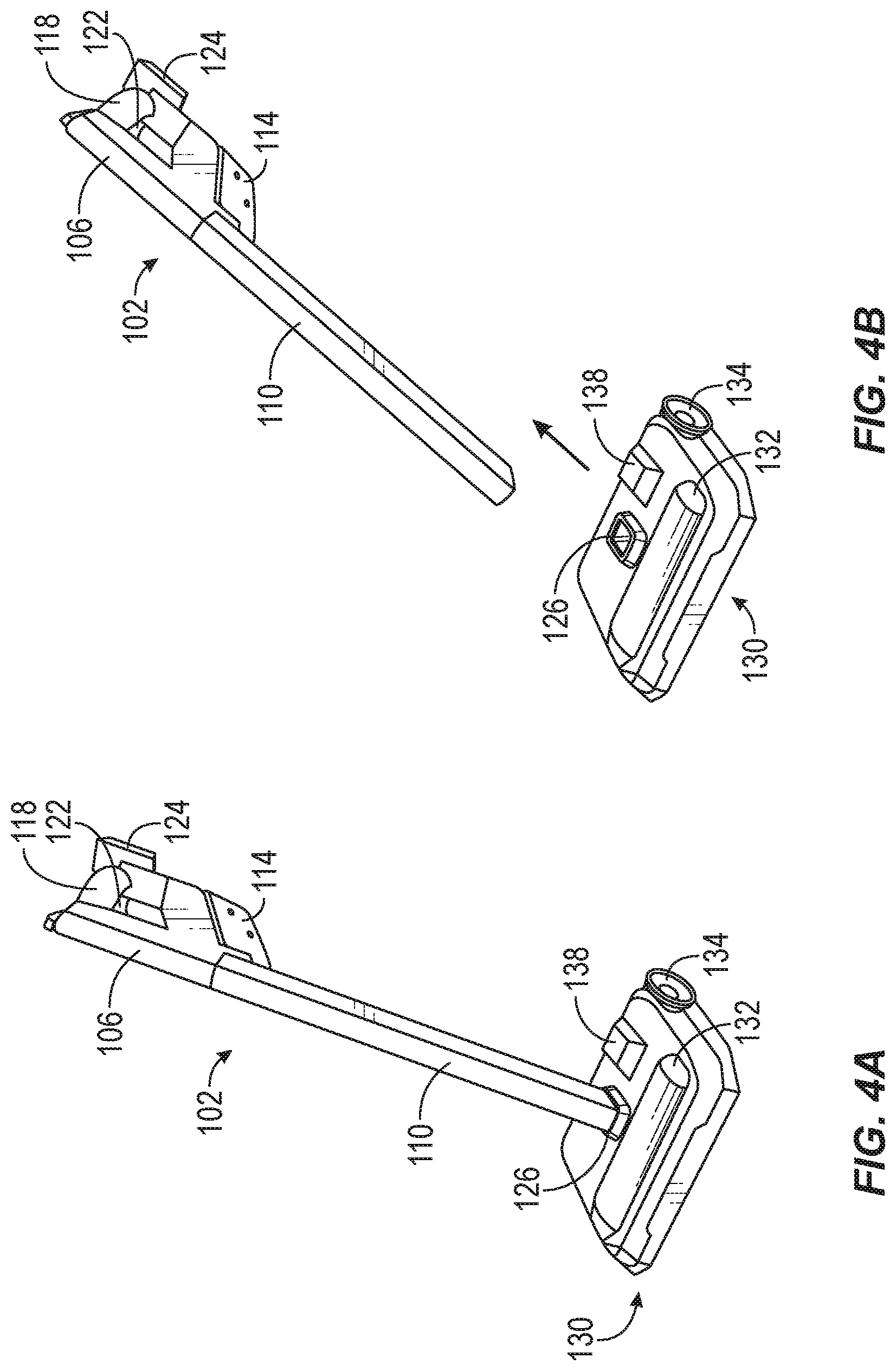
[0020] FIG. 4A is a perspective view of a vacuum cleaner according to another embodiment of the invention, coupled to a power base.
[0021] FIG. 4B is a perspective view of the vacuum cleaner of 4A removed from the power base.
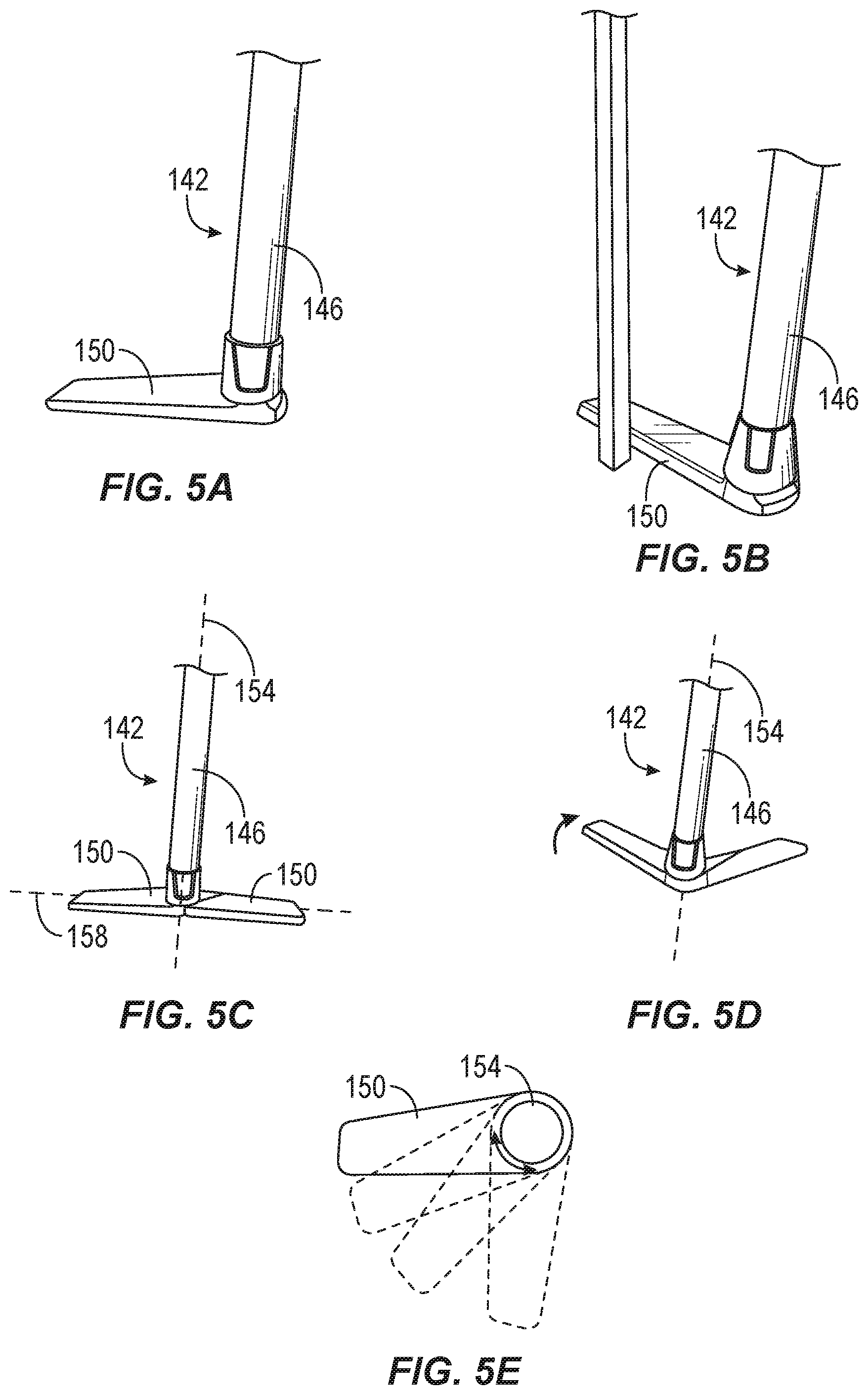
[0022] FIG. 5A is perspective view of a vacuum cleaner according to another embodiment of the invention.
[0023] FIG. 5B is a perspective view of the vacuum cleaner of FIG. 5A.
[0024] FIG. 5C is a perspective view of a vacuum cleaner according to another embodiment of the invention.
[0025] FIG. 5D is perspective view of the vacuum cleaner of FIG. 5C.
[0026] FIG. 5E is a cross-sectional view of the vacuum cleaner of FIG. 5A showing different positions of a wing of the vacuum cleaner.
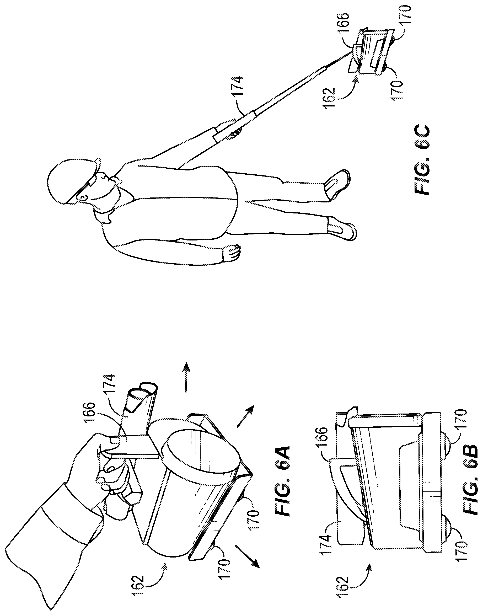
[0027] FIG. 6A is a perspective view of a vacuum cleaner according to another embodiment of the invention.
[0028] FIG. 6B is a plan view of the vacuum cleaner of FIG. 6A.
[0029] FIG. 6C is a perspective view of the vacuum cleaner of FIG. 6A.
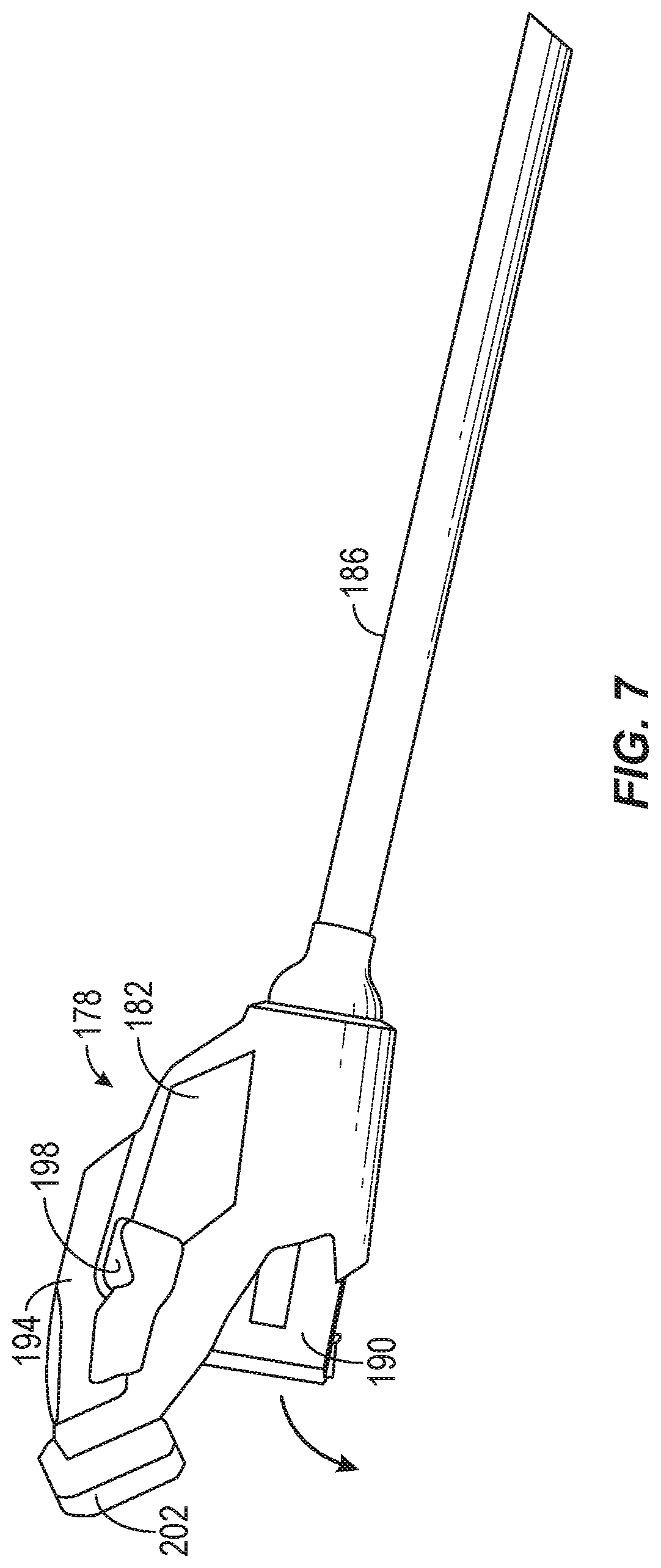
[0030] FIG. 7 is a plan view of a vacuum cleaner according to another embodiment of the invention.
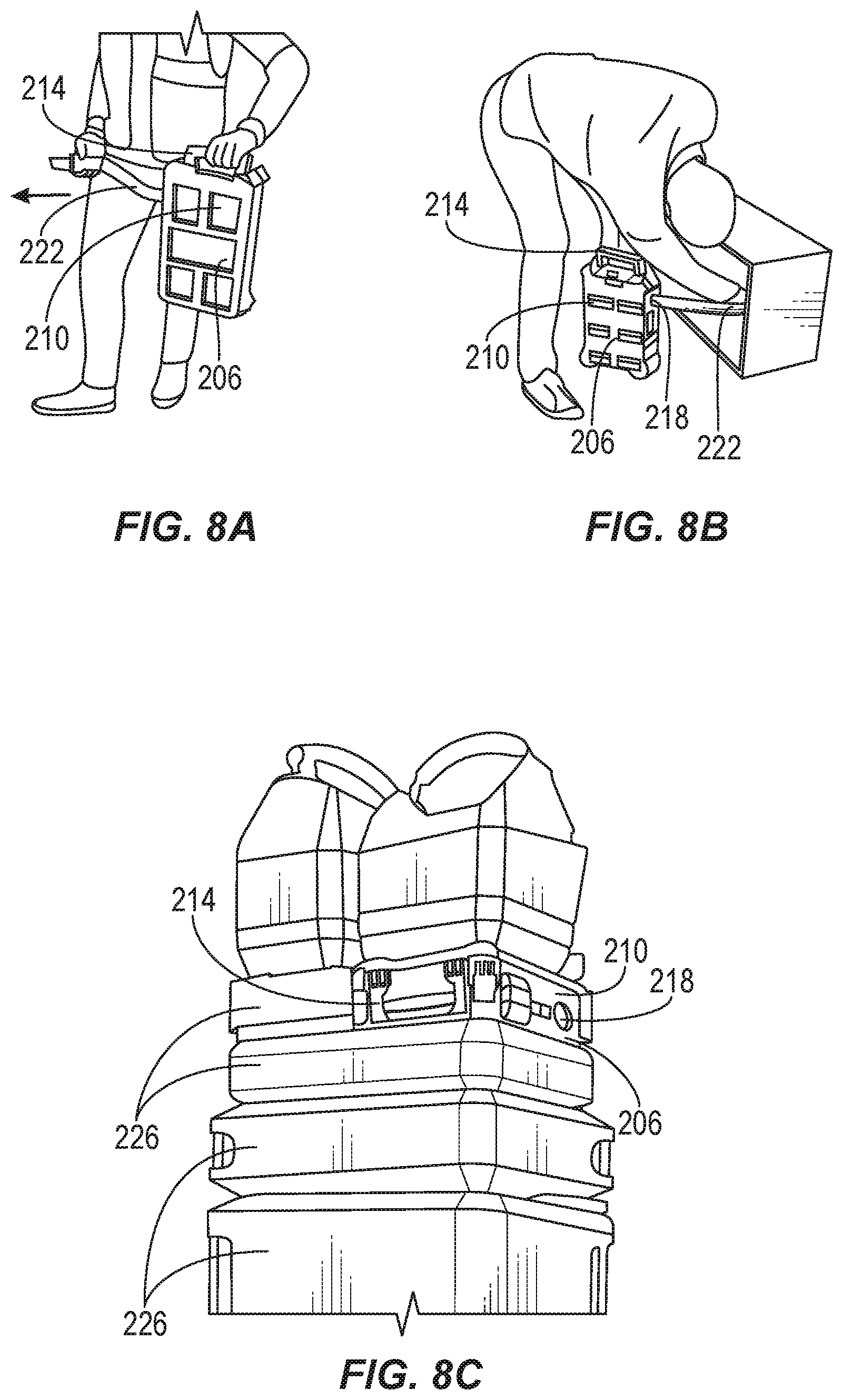
[0031] FIG. 8A is a perspective view of a vacuum cleaner according to another embodiment of the invention.
[0032] FIG. 8B is a perspective view of the vacuum cleaner of FIG. 8A.
[0033] FIG. 8C is a perspective view of the vacuum cleaner of FIG. 8A being stacked among a plurality of tool boxes.
[0034] FIG. 9A is a plan view of a vacuum cleaner according to another embodiment of the invention, being separated from a holster.
[0035] FIG. 9B is a plan view of the vacuum cleaner of FIG. 9A opening a door to empty debris.
[0036] FIG. 9C is a plan view of the vacuum cleaner of FIG. 9A coupled to the holster.
[0037] FIG. 10A is a plan view of a vacuum cleaner according to another embodiment of the invention, separated from a rotary power tool.
[0038] FIG. 10B is a plan view of the vacuum cleaner of FIG. 10A coupled to the rotary power tool.
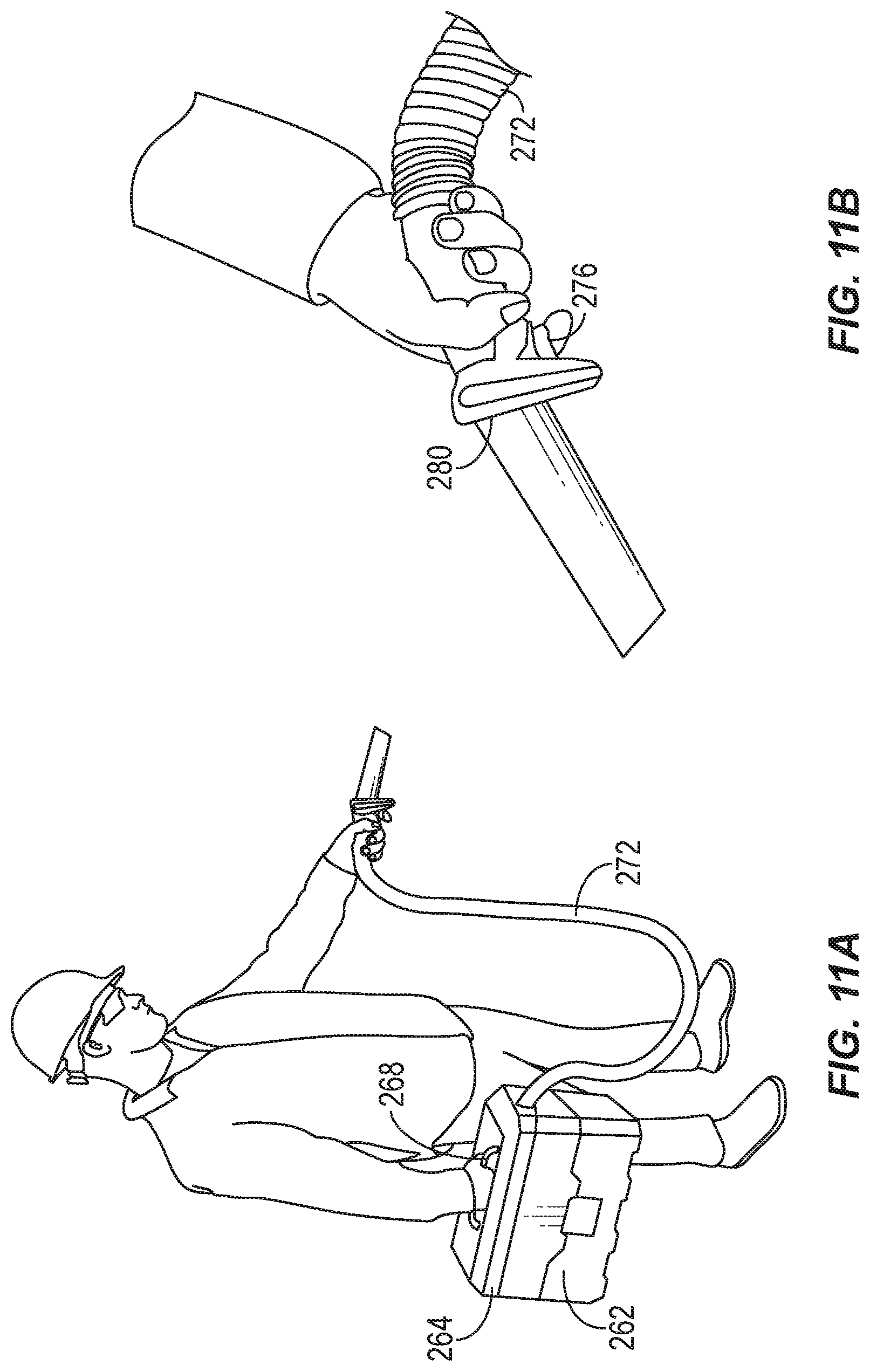
[0039] FIG. 11A is a perspective view of a vacuum cleaner according to another embodiment of the invention.
[0040] FIG. 11B is an enlarged perspective view of a hose of the vacuum cleaner of FIG. 11A.
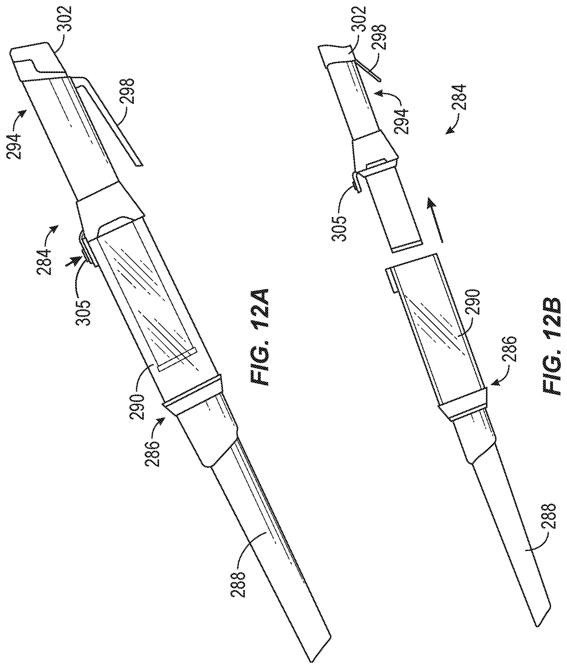
[0041] FIG. 12A is a plan view of a vacuum cleaner according to another embodiment of the invention.
[0042] FIG. 12 B is a plan view of the vacuum cleaner of FIG. 12A, with a first portion separated from a handle portion.
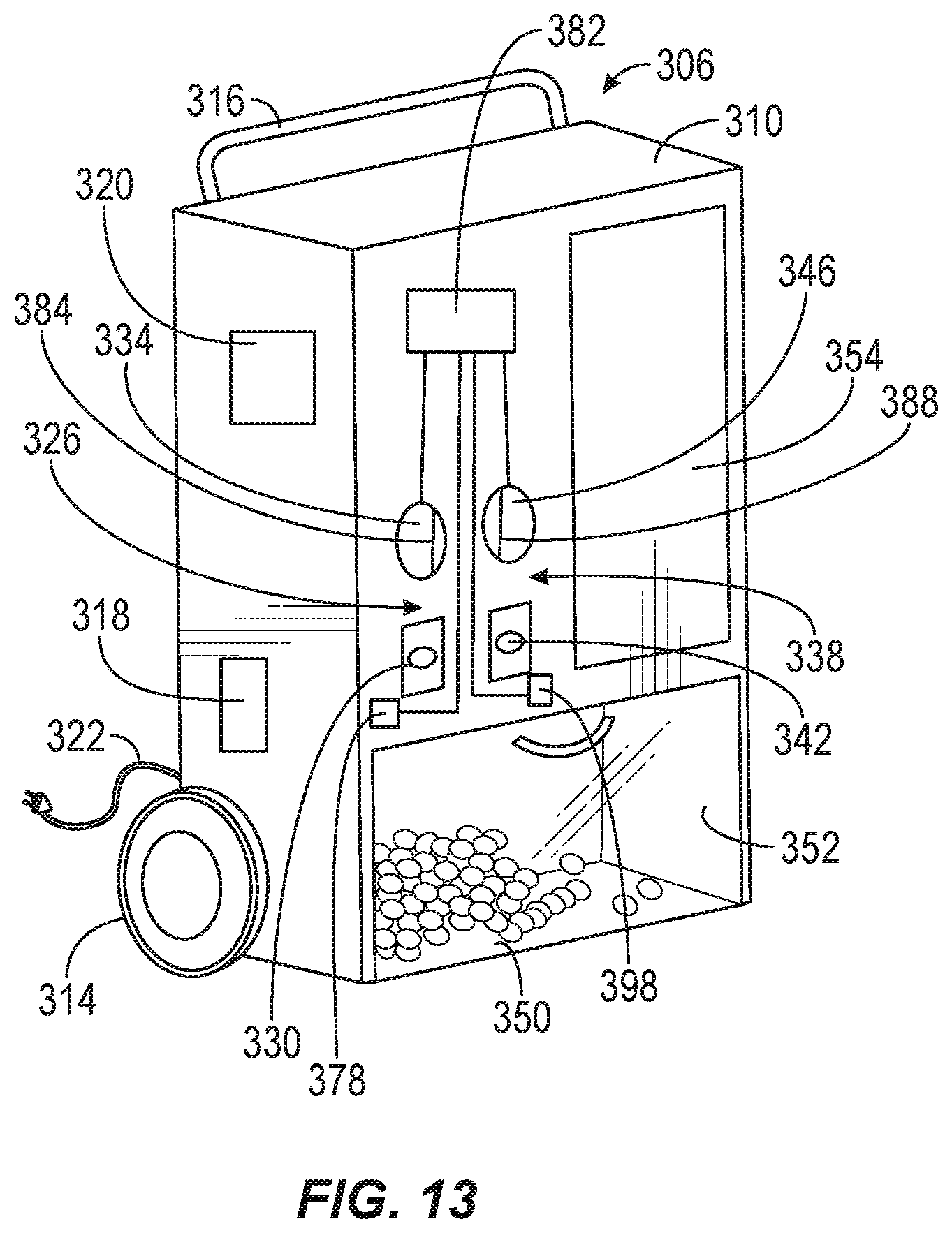
[0043] FIG. 13 is a perspective view of a vacuum cleaner according to another embodiment of the invention.
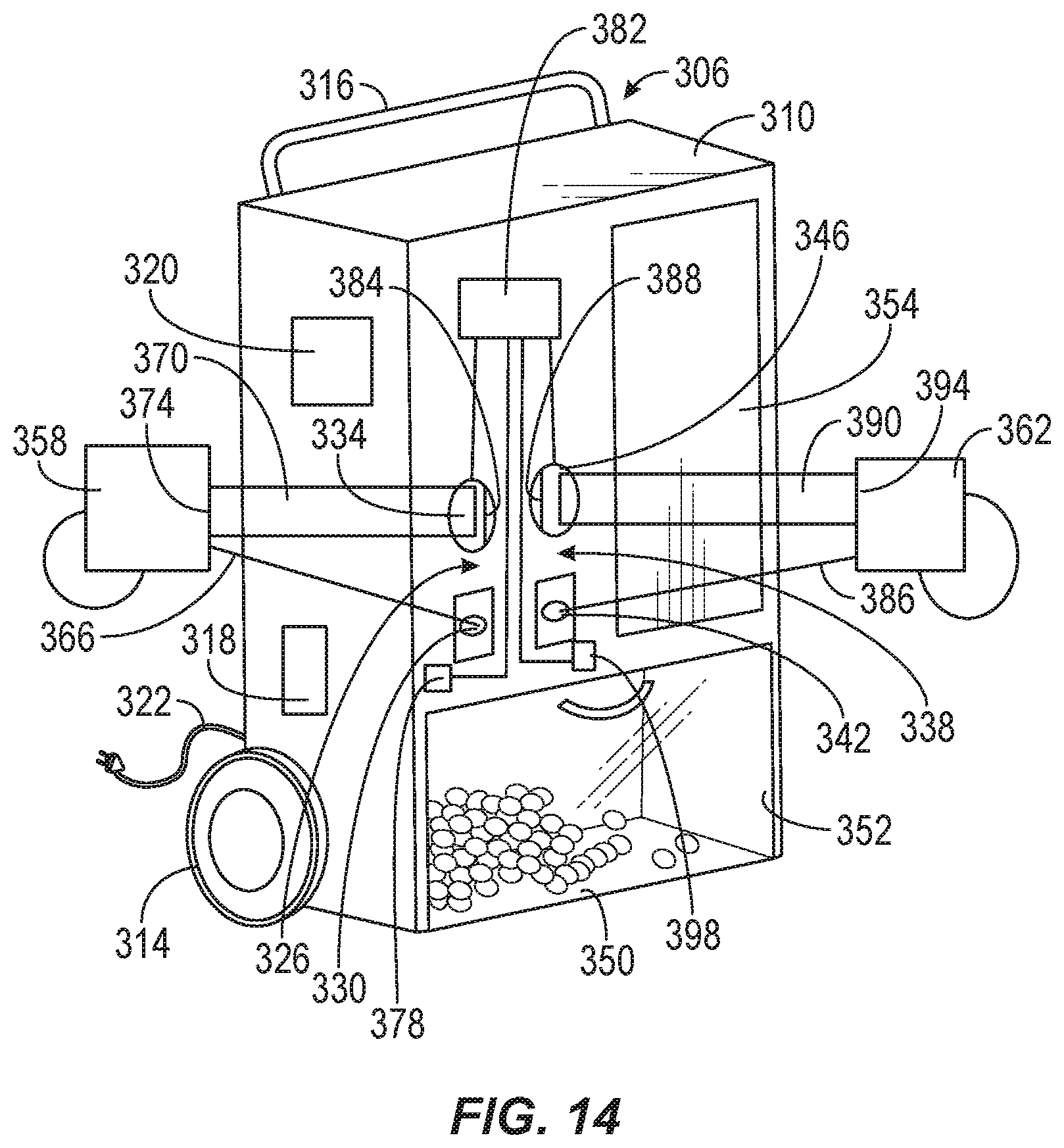
[0044] FIG. 14 is a perspective view of the vacuum cleaner of FIG. 13, with two power tools coupled thereto.
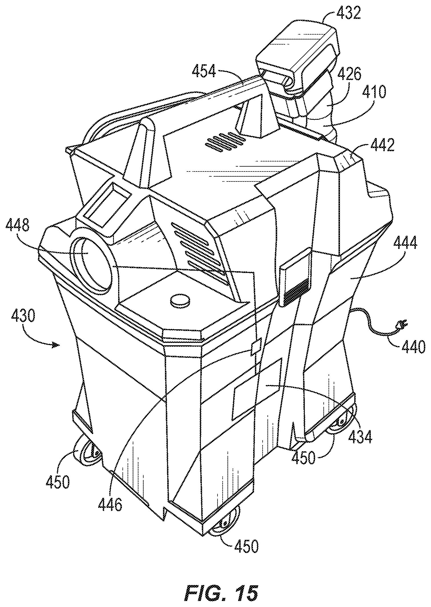
[0045] FIG. 15 is a perspective view of a vacuum cleaner according to another embodiment of the invention, with a hand held vacuum cleaner docked therein.
[0046] FIG. 16 is a plan view of the vacuum cleaner of the vacuum cleaner of FIG. 15, with the hand held vacuum cleaner docked therein.
[0047] FIG. 17 is a perspective view of the hand held vacuum cleaner of FIG. 15.
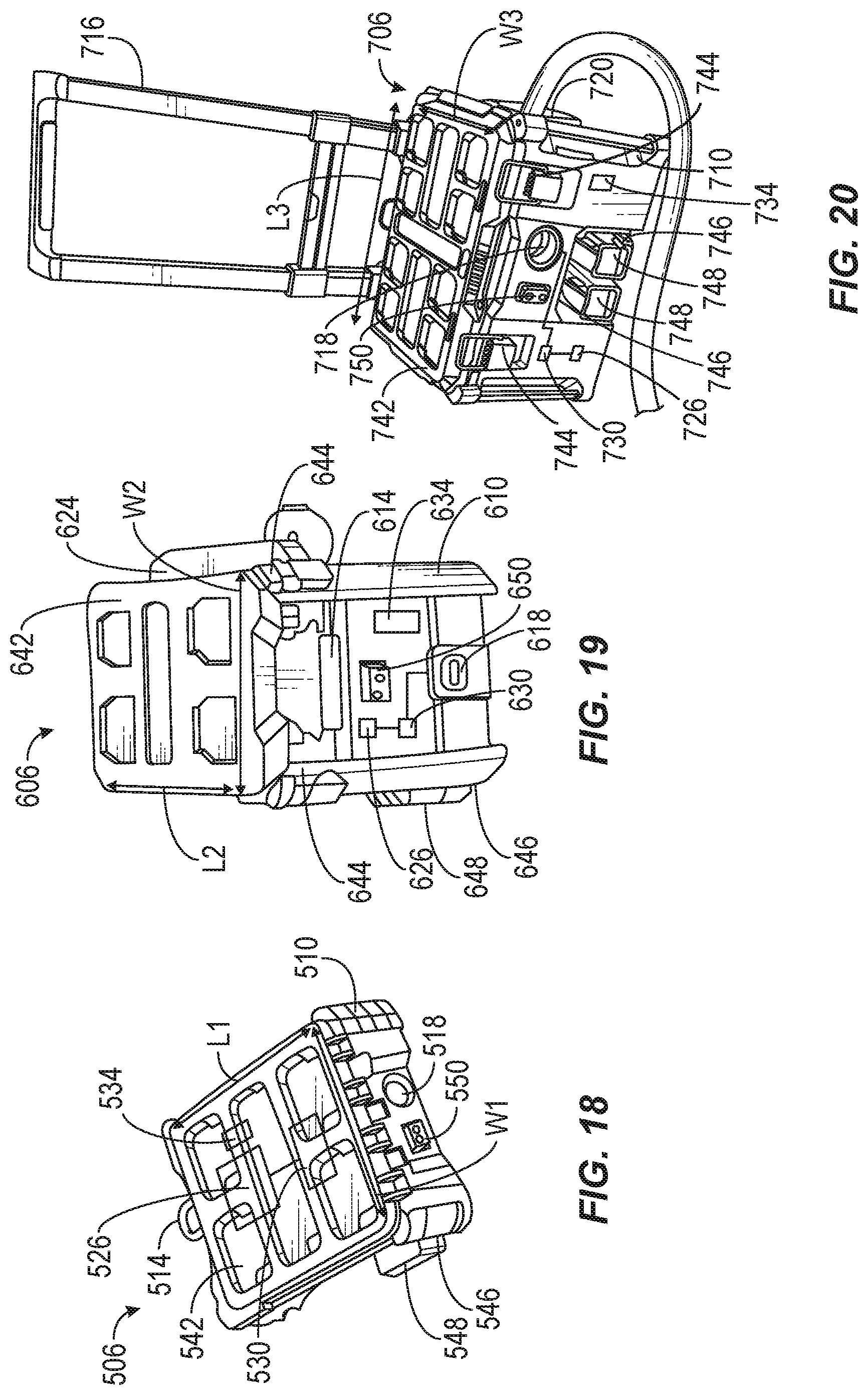
[0048] FIG. 18 is a perspective view of a vacuum cleaner according to another embodiment of the invention.
[0049] FIG. 19 is a perspective view of a vacuum cleaner according to another embodiment of the invention.
[0050] FIG. 20 is a perspective view of a vacuum cleaner according to another embodiment of the invention.
[0051] FIG. 21 is a perspective view of the vacuum cleaner of FIG. 19 stacked upon two of the vacuum cleaners of FIG. 20.
[0052] FIG. 22 is a perspective view of the vacuum cleaner of FIG. 18.
[0053] FIG. 23 is a perspective view of a vacuum cleaner according to another embodiment of the invention.
[0054] FIG. 24 is an enlarged cross-sectional view of the vacuum cleaner of FIG. 22.
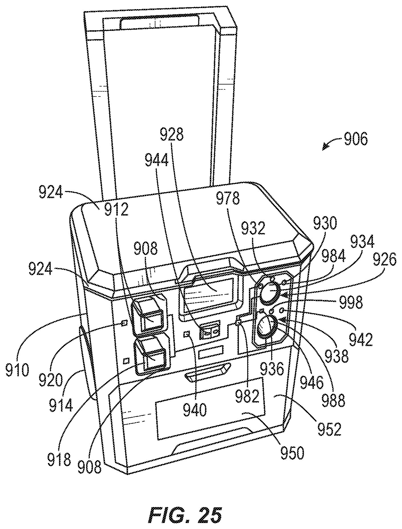
[0055] FIG. 25 is a perspective view of a vacuum cleaner according to another embodiment of the invention.
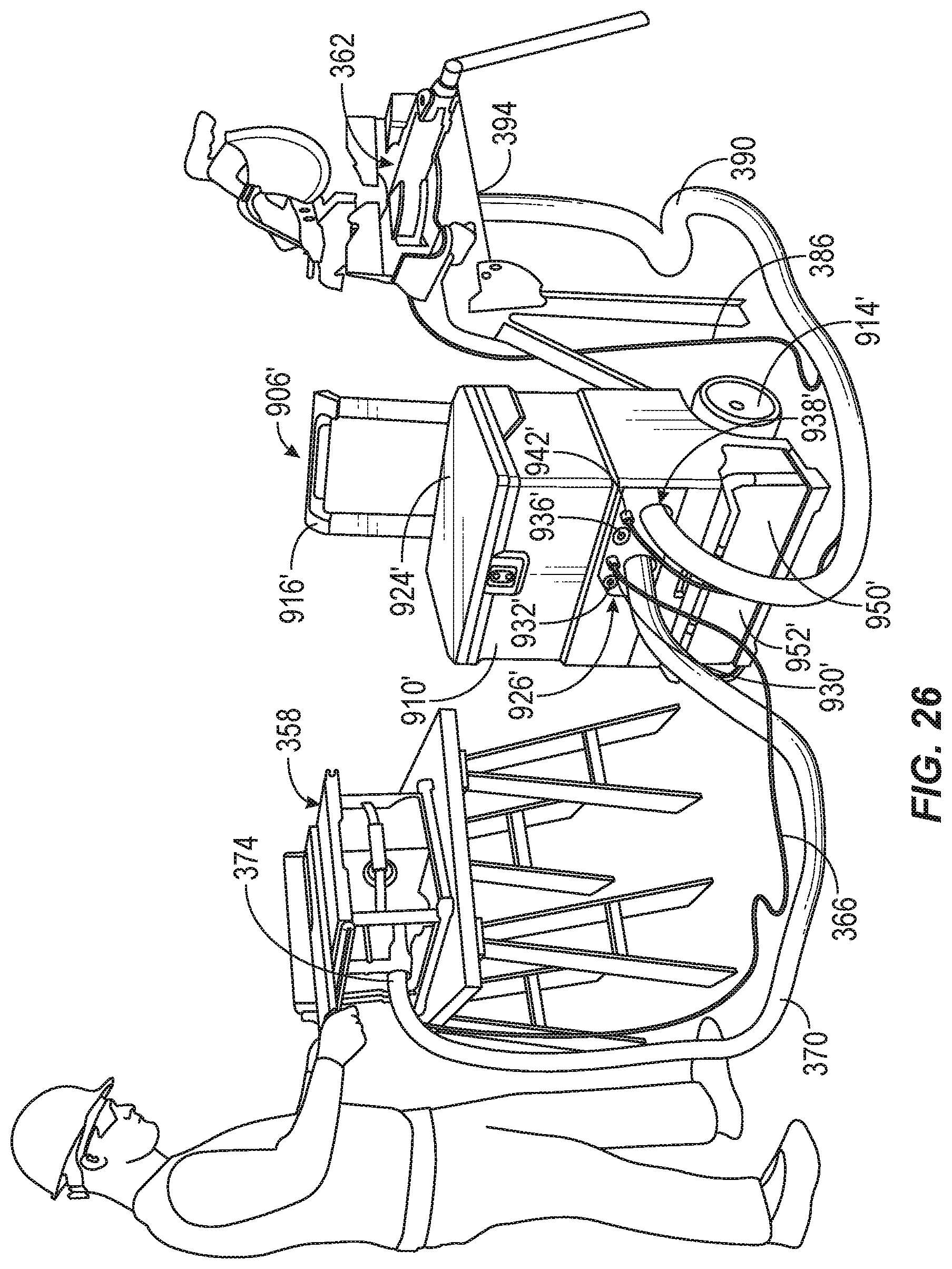
[0056] FIG. 26 is a perspective view of the vacuum cleaner of claim 25 with two power tools coupled thereto.
[0057] FIG. 27 is a perspective view of a vacuum cleaner according to another embodiment of the invention.
[0058] FIG. 28 is an enlarged perspective view of the vacuum cleaner of claim 27, with portions removed.
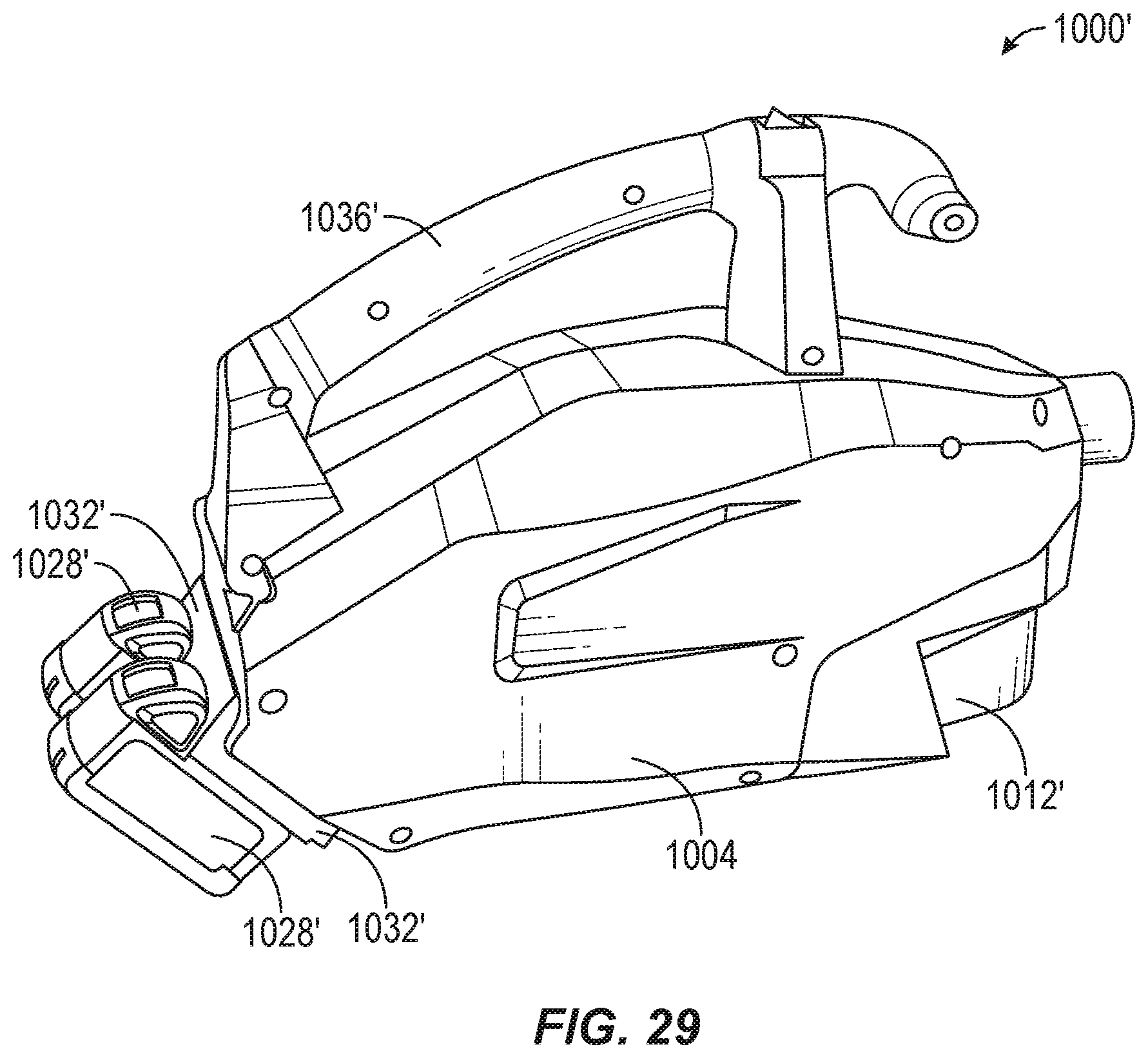
[0059] FIG. 29 is a perspective view of a vacuum cleaner according to another embodiment of the invention.
[0060] Before any embodiments of the invention are explained in detail, it is to be understood that the invention is not limited in its application to the details of construction and the arrangement of components set forth in the following description or illustrated in the following drawings. The invention is capable of other embodiments and of being practiced or of being carried out in various ways. Also, it is to be understood that the phraseology and terminology used herein is for the purpose of description and should not be regarded as limiting.
DETAILED DESCRIPTION
[0061] As shown in FIGS. 1A-1D, a vacuum cleaner 10 includes a body 14, a suction nozzle 18, a debris collection chamber 22, a handle 26, and a trigger 28 for actuating a suction motor (not shown) that is powered by a power source such as a battery or battery pack 32. The vacuum cleaner 10 is insertable into a station 30 having a dust bin 34. When the vacuum cleaner 10 is inserted into the station 30, the battery or battery pack 32 can be recharged via the station 30 (FIG. 1C). Also, while the vacuum cleaner 10 is inserted in the station 30, a button 38 on the station 30 is depressible to cause the contents of the debris collection chamber 22 of the vacuum cleaner 10 to empty into the dust bin 34 of the station 30 (FIG. 1D). The station 30 includes a power cord 40 for plugging into an AC electrical outlet 41.
[0062] FIG. 17 illustrates a vacuum cleaner 410 that is substantially similar to the vacuum cleaner 10 FIGS. 1A-1D, with like parts having the same annotation plus "400". Similarly, FIGS. 15 and 16 illustrate a vacuum cleaner 430 that is substantially identical to the station 30 of FIG. 1A-1D, with like parts having the same annotation plus "400". However, unlike station 30, vacuum cleaner 430 is a vacuum cleaner. Like the embodiment shown in FIGS. 1A-1D, the vacuum cleaner 410 is insertable into the vacuum cleaner 430 having a dust bin 434. When the vacuum cleaner 410 is inserted into the vacuum cleaner 430, the battery or battery pack 432 can be recharged via the vacuum cleaner 430 (FIGS. 15 and 16), via the power cord 440. Also, while the vacuum cleaner 410 is inserted in the vacuum cleaner 430, a button 438 on the vacuum cleaner 430 is depressible to cause the contents of the debris collection chamber 422 of the vacuum cleaner 410 to empty into the dust bin 434 of the vacuum cleaner 430.
[0063] In addition, the vacuum cleaner 430 has several additional features and differences, in comparison with the station 30, that are explained below. The vacuum cleaner includes a lid 442 that is separable from a body 444, to allow access to the dust bin 434 in the body 444. The vacuum cleaner 430 includes a plurality of latches 445 to secure the lid 442 to the body 444. The vacuum cleaner 410 mounts the vacuum cleaner 430 through the lid 442. The vacuum cleaner 430 also includes a suction source 446, such as a motor-driven fan, that receives power via the power cord 440. The suction source 446 is fluidly connected to a hose port 448 and the dust bin 434, such that a hose can be coupled to the hose port 448, and the suction source 446 can be run to suction material through the hose port 446 and into the dust bin 434. Thus, unlike the station 30, the vacuum cleaner 430 can be operated as an independent canister vacuum cleaner. Further, the body 444 includes a plurality of wheels 450, such as castor wheels, and the lid includes a handle 454, making it easier for an operator to wheel the vacuum cleaner 430 between different spots at a job site to suction debris. However, when the smaller, cordless, battery-powered vacuum cleaner 410 is needed to reach a tight corner or spot that is inaccessible to vacuum cleaner 430, the operator may decouple vacuum cleaner 410 from the vacuum cleaner 430.
[0064] As shown in FIGS. 2A and 2B, a vacuum cleaner 42 includes a body 46, a suction nozzle 50, a debris collection chamber 54, a handle 58, and a trigger 62 for actuating a suction motor (not shown) that is powered by a power source such as a battery or battery pack (not shown). The suction nozzle 50 includes a nose 66 with a first suction opening 70 and an extension 74 from body 46 that has a second suction opening 78. When the nose 66 is in a first position (FIG. 2A), the nose 66 extends along an axis 80 that is defined by the extension 74, and the second suction opening 78 is covered by the nose 66. Thus, when operated in the first position, dirty air passes into the first suction opening 70, through the nose 66, through the extension 74, and into the debris collection chamber 54. When the nose is pivoted about a pivot joint 82 from the first position to a second position in which the nose 66 does not lie along the axis 80 defined by the extension 74 (FIG. 2B), operation of the vacuum cleaner 10 causes dirty air to enter directly through the second suction opening 78, rather than passing through first suction opening 70 and nose 66.
[0065] As shown in FIG. 3, a vacuum cleaner 86 includes a body 90, a suction nozzle 94, a debris collection chamber (not shown), a handle 96, and a trigger (not shown) for actuating a suction motor (not shown) that is powered by a power source such as a battery or battery pack (not shown). The handle is graspable with one hand 98 of an operator and the nozzle 94 is adept at cleaning small messes.
[0066] As shown in FIGS. 4A and 4B, a vacuum cleaner 102 includes a body 106, a suction nozzle 110, a debris collection chamber 114, a handle 118, and a trigger 122 for actuating a suction motor (not shown) that is powered by a power source such as a battery or battery pack 124. The vacuum cleaner 102 is insertable into a receptacle 126 of a powered base 130 for floor operations. The powered base 130 includes a brushroll indicated at 132, wheels 134, and a release actuator 138. In operation, as shown in FIG. 4A, the suction nozzle 110 is inserted into the receptacle 126 and the trigger 122 is depressed to operate the vacuum cleaner 102 and the powered base 130. Specifically, air and debris is suctioned from under powered base 130 and into the suction nozzle 110 before entering the debris collection chamber 114. In some embodiments, the power source of vacuum cleaner 102 may power the brushroll 132 of the powered base 130. In other embodiments, powered base 130 is powered separately. When finished with floor operations, the operator hits release actuator 138 to release the suction nozzle 110 from the receptacle 126, thus allowing the vacuum cleaner 102 to be used without powered base 130, as shown in FIG. 4B.
[0067] As shown in FIG. 5, a suction nozzle 142 for a vacuum cleaner includes a wand portion 146 and one (FIGS. 5A and 5B) or more (FIGS. 5C and 5D) wings 150 which glide along a surface during cleaning. The one or more wings 150 communicate suctioned air to wand portion 146 and can pivot about an axis 154 defined by the wand portion 146, thus allowing wings to pivot about axis 154 when striking obstacles during cleaning. In the embodiment shown in FIGS. 5C and 5D, the wings 150 are biased towards a neutral position in which they are arranged along the same axis 158.
[0068] As shown in FIGS. 6A-6C, a vacuum cleaner 162 includes a body handle 166, omnidirectional castors 170, and a telescoping handle 174 allowing an operator to push the vacuum cleaner 162 around a floor.
[0069] As shown in FIG. 7, a vacuum cleaner 178 includes a body 182, a suction nozzle 186, a debris collection chamber 190, a handle 194, and a trigger 198 for actuating a suction motor (not shown) that is powered by a power source such as a battery or battery pack 202. The debris collection chamber 190 is removable from the body 182 of the vacuum cleaner 178.
[0070] As shown in FIGS. 8A-8C, a vacuum cleaner 206 has a body 210 with a shape of a tool box, a handle 214 and a port 218 for attaching a hose 222 for a suction operation. Thus, the vacuum cleaner 206 is stackable among a plurality of other tool boxes 226.
[0071] FIGS. 18 and 22 illustrates a vacuum cleaner 506 having a housing 510 with a shape of a flat tool box, a handle 514 and a hose port 518 for attaching a hose 522 for a suction operation. As shown in FIGS. 18 and 22, the housing 510 has a length L1 and a width W1. The hose port 518 can be arranged along different sides of the vacuum cleaner 506, as shown by comparison between FIGS. 18 and 22. The vacuum cleaner 506 includes a suction source 526, such as a motor-driven fan, that is in fluid communication with the hose port 518 and a debris collection chamber 530 in the housing 510. The housing 510 also includes a storage space 534 including a plurality of compartments 538 to store, for example, different tools and worksite accessories.
[0072] A lid 542 is coupled to the housing 510 and is moveable between an open position, in which access to the storage space 534 is provided, and a closed position, in which access to the storage space 534 is blocked. In the embodiment shown in FIG. 22, the lid 542 is transparent, such that an operator can identify what tools and accessories are stored in the different compartments 538 of the storage space 534. In some embodiments, the lid 542 can be moved to the open position to provide access to the debris collection chamber 530 and in some embodiments, the lid 542 can be moved to the open position to provide access to the suction source 526. The vacuum cleaner 506 also includes a battery receptacle 546 for receipt of a battery pack 548 that is configured to power the suction source 526 when received in the battery receptacle 546. In some embodiments, the battery pack 548 is a 12V battery pack. The vacuum cleaner 506 also includes an actuator 550 on the housing 510, such that moving the actuator 550 from an "OFF" position to an "ON" position, while the battery pack 548 is in the battery receptacle 546, turns on the suction source 526 to suction debris through the hose port 518 and into the debris collection chamber 530.
[0073] FIGS. 19, 21 and 22 illustrate a vacuum cleaner 606 having a housing 610 with a shape of a medium-sized toolbox that is larger than the housing 510 of the vacuum cleaner 506. As shown in FIGS. 18 and 22, the housing 610 has a length L2 and a width W2 that are respectively similar or identical to the length L1 and width W1 of the housing 510 of the vacuum cleaner 506. Thus, since several dimensions are similar or identical, the vacuum cleaner 506 may be stacked on top of the vacuum cleaner 606 in a more convenient and orderly manner. The vacuum cleaner 606 also includes a pair of handles 614 and a hose port 618 for attaching the hose 522 for a suction operation. The vacuum cleaner 606 also includes a bracket 624 on which the hose 522 can be stored, as shown in FIG. 21. The vacuum cleaner 606 includes a suction source 626, such as a motor-driven fan, that is in fluid communication with the hose port 618 and a debris collection chamber 630 in the housing 610.
[0074] The housing 610 also includes a storage space 634 including a plurality of compartments 638 to store, for example, different tools and worksite accessories. A lid 642 is coupled to the housing 610 and is moveable between an open position, in which access to the storage space 634 is provided, and a closed position, in which access to the storage space is blocked. A plurality of latches 644 are used to secure the lid 642 in the closed position. In the embodiments shown in FIGS. 21 and 22, the lid 642 is transparent, such that an operator can identify what tools and accessories are stored in the different compartments 638 of the storage space 634. The vacuum cleaner 606 also includes a battery receptacle 646 for receipt of a battery pack 648 that is configured to power the suction source 626 when received in the battery receptacle 646. In some embodiments, the battery pack 648 is an 18V battery pack. The vacuum cleaner 606 also includes an actuator 650 on the housing 610, such that moving the actuator 650 from an "OFF" position to an "ON" position, while the battery pack 648 is in the battery receptacle 646, turns on the suction source 626 to suction debris through the hose port 618 and into the debris collection chamber 630.
[0075] FIGS. 20-22 illustrate a vacuum cleaner 706 having a housing 710 with a shape of a large-sized toolbox that is larger than the housings 510, 610 of the vacuum cleaners 506, 606. As shown in FIG. 20, the housing 710 has a length L3 and a width W3 that are respectively similar or identical to at least one of the lengths L1, L2 and widths W1, W2 of the housings 510, 610 of the vacuum cleaners 506, 606. Thus, since at least one dimension is similar or identical, the vacuum cleaners 506, 606 may be stacked on top of the vacuum cleaner 706 in a more convenient and orderly manner. The vacuum cleaner 706 also includes a pair of side handles 714, a telescoping handle 716, and a hose port 718 for attaching the hose 522 for a suction operation. The vacuum cleaner 706 also includes a pair of wheels 720, such that by grasping the telescoping handle 716, an operator can tilt the vacuum cleaner 706 and roll it along a surface. The vacuum cleaner 706 includes a suction source 726, such as a motor-driven fan, that is in fluid communication with the hose port 718 and a debris collection chamber 730 in the housing 710.
[0076] The housing 710 also includes a storage space 734 including a plurality of compartments to store, for example, different tools and worksite accessories. A lid 742 is coupled to the housing 710 and is moveable between an open position, in which access to the storage space 634 is provided, and a closed position, in which access to the storage space is blocked. A plurality of latches 744 are used to secure the lid 742 in the closed position. The vacuum cleaner 606 also includes two battery receptacles 746 that can each receive a battery pack 748 that is configured to power the suction source 726 when received in the battery receptacle 746. In some embodiments, the battery packs 748 are 18V battery packs. The vacuum cleaner 706 also includes an actuator 750 on the housing 710, such that moving the actuator 750 from an "OFF" position to an "ON" position, while the battery packs 748 are in the battery receptacles 746, turns on the suction source 726 to suction debris through the hose port 718 and into the debris collection chamber 730.
[0077] As shown in FIG. 9, a vacuum cleaner 230 is configured to be received in a holster 238 that can be worn on the hip or a belt 240 of an operator. In some embodiments, the holster 238 has ribs 242 that mate with grooves (not shown) on the vacuum cleaner 230. Thus, the vacuum cleaner 230 can be worn on the operator's body or hip without needing to be carried by the operator. The vacuum cleaner 230 also has a pivotable door 246 that can be opened downwardly to empty the dirt and debris contents collected form a cleaning operation.
[0078] As shown in FIG. 10, a vacuum cleaner 250 includes a mount 254 configured to receive a rotary power tool 258. When the power tool 258 is mounted in the mount 254, operation of the power tool 258 drives a suction motor (not shown) of the vacuum cleaner 250.
[0079] As shown in FIG. 11, a vacuum cleaner 262 has a body 264 with a shape of a tool box, a handle 268 and a hose 272 for a suction operation. The hose 272 includes wiring (not shown) that leads to a trigger 276 at a suction head 280. Thus, pressing the trigger 276 operates the suction motor (not shown) in the vacuum cleaner 262.
[0080] As shown in FIG. 12, a vacuum cleaner 284 includes first portion 286 including a suction nozzle 288 and a debris collection chamber 290 and a handle portion 294 including a paddle trigger 298 for actuating a suction motor in the handle portion 294 that is powered by a power source such as a battery or battery pack 302. By pressing a release actuator 305 on the handle portion 294, the first portion 286 is removable from the handle portion 294 to allow the debris collection chamber 290 to be emptied.
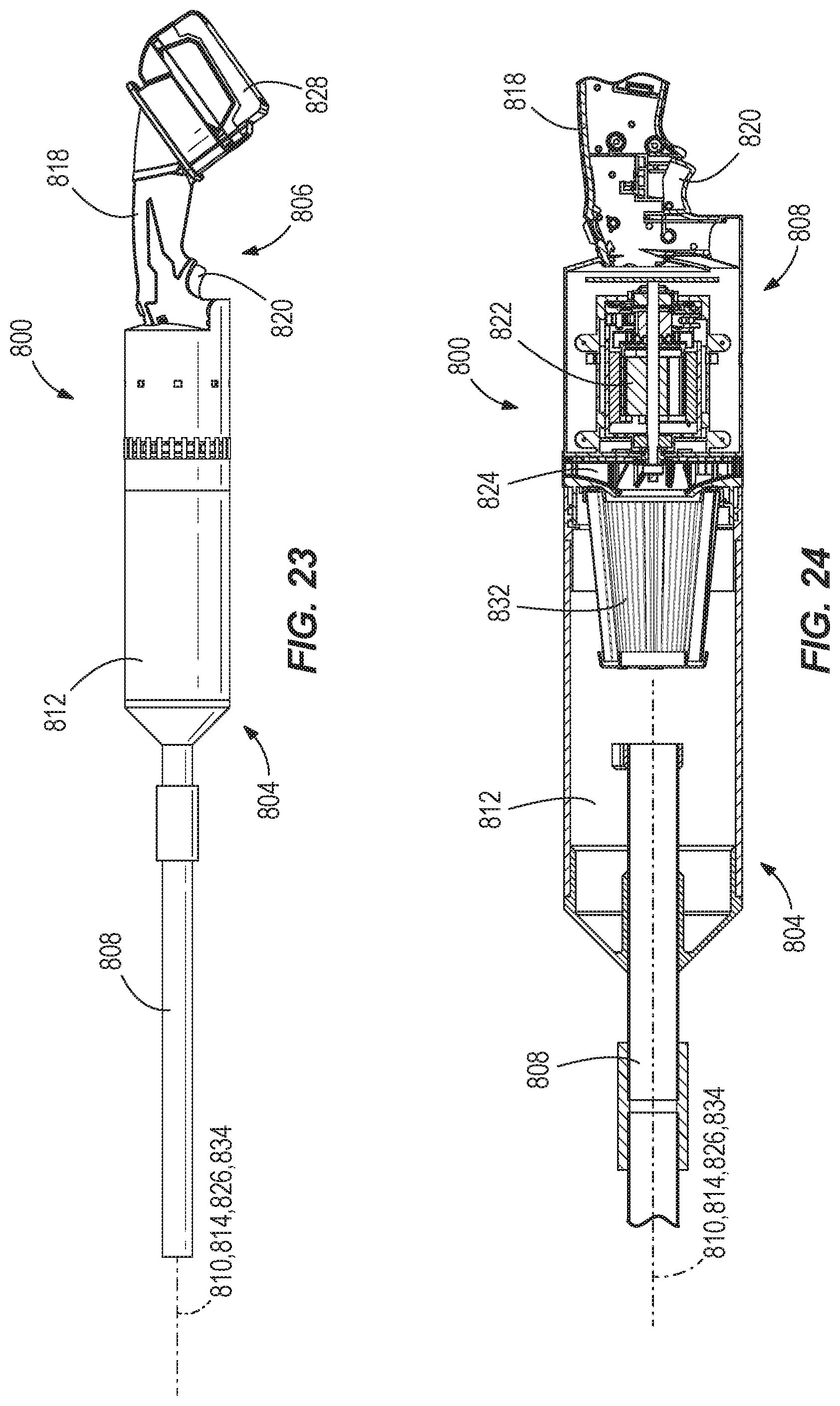
[0081] FIGS. 23 and 24 illustrate a vacuum cleaner 800 includes first portion 804 including a nozzle 808 defining a first axis 810 and a debris collection chamber 812 defining a second axis 814. The vacuum cleaner also includes a second portion 816 includes a handle 818 and a trigger 820 for actuating a motor 822 that rotates a fan 824 to generate suction in the second portion 816. The first portion 804 is removably coupled to the second portion 816. The motor 822 defines a third axis 826 and is powered by a removably attachable battery pack 828 on the handle 818 of the second portion 816. In some embodiments, the battery pack 828 is a 12V battery pack and in other embodiments, the battery pack 828 is an 18 V battery pack. A pre-motor filter 832 defining a fourth axis 834 is arranged on the second portion 816 such that when the first portion 804 is coupled to the second portion 816, the filter 832 is arranged within the debris collection chamber 812, and the first 810, second 814, third 826, and fourth axes 834 are all coaxial and intersecting the handle 818 and the battery pack 828.
[0082] When the first portion 804 is coupled to the second portion 816, the vacuum cleaner 800 has a small form factor, making it easy for an operator to operate with one hand by grasping the handle 818. In operation, the operator may depress the trigger 820 to generate suction through the nozzle 808 to draw dirt and debris into the debris collection chamber 812. Air then continues to flow through the filter 832, where smaller particulate matter is filtered from the airflow, which is then exhausted through vents 836 on the second portion 816. After the suction operation has been completed, when the suction operator first portion 804 is removed from the second portion 816, the debris collection chamber 812 can be emptied. When the operator is done using the vacuum cleaner 800, the nozzle 808 is removable from the debris collection chamber 812, the vacuum cleaner 800 can be conveniently stored.
[0083] As shown in FIG. 13, a vacuum cleaner 306 includes a body 310, a plurality of wheels 314, and a handle 316 to allow an operator to pull the body 310 along the ground with the wheels 314. The vacuum cleaner 306 also includes a suction source 318, such as a motor with a fan, and a cyclonic separator 320 inside the body 310. The vacuum cleaner 306 also includes a filter fluidly coupled to the suction source and the cyclone separator. The vacuum cleaner 306 also includes an AC power cord 322 configured to attach to an AC power source, such as an electrical outlet, to provide power to the suction source 318. The vacuum cleaner 306 also includes a first tool interface 326 with a first outlet 330 and a first hose port 334, as well as a second tool interface 338 with a second outlet 342 and a second hose port 346. The vacuum cleaner 306 also includes a primary debris bin 350 behind a door 352 and a secondary debris bin behind a door 354. In some embodiments, the door 352 is transparent to allow an operator to observe how much dust and debris has accumulated in the primary debris bin 350, thus improving the life of the filter.
[0084] In operation, as shown in FIG. 14, an operator such as residential or commercial finish carpenter may need to use first and second power tools 358, 362 during the installation of finish woodwork on a jobsite. The operator thus plugs the AC power cord 322 of the vacuum cleaner 306 into an electrical outlet and plugs a first power cord 366 of the first power tool 358, such as a table saw, into the first outlet 330 of the first tool interface 326. The operator also couples a first hose 370 between a debris outlet 374 of the first power tool 358 and the first hose port 334 of the first tool interface 326.
[0085] The operator then turns on the first power tool 358 and uses it to perform a cutting or sawing operation, which causes dust and debris to exit the debris outlet 374 of the first power tool 358. When the first power tool 358 is turned on, a first sensor 378 in electrical communication with the first outlet 330 indicates to a controller 382 that the first power tool 358 has been turned on and is drawing current from the first outlet 330. In response, the controller 382 turns on the suction source 318 opens a first blast valve 384, such as a gate, (FIG. 13) of the first hose port 334, thus causing the suction source 318 to suction dust and debris from the debris outlet 374 of the first power tool 358 via the first hose 370 and the first hose port 334. The dust and debris is suctioned through the cyclonic separator 320, resulting in larger debris falling to the primary debris bin 350 through the cyclonic action of the cyclonic separator 320. After passing through the cyclonic separator 320, additional dust and debris is captured in the secondary debris bin behind door 354. In some embodiments, the cyclone separator 320 collects 97% of the debris in the primary debris bin 350.
[0086] When the operator is finished using the first power tool 358, the operator turns off the first power tool 358 and the first sensor 378 indicates to the controller 382 that the first power tool 358 is no longer drawing current from the first outlet 330. In response, the controller 382 closes the first blast valve 384 of the first hose port 334 and turns off the suction source 318.
[0087] The operator may then wish to use the second power tool 362, such as a miter saw. The operator thus plugs a second power cord 386 of the second power tool 362 into the second outlet 342 of the second tool interface 338. The operator also couples a second hose 390 between a debris outlet 394 of the second tool 362 and the second hose port 346 of the second tool interface 338.
[0088] The operator then turns on the second power tool 362 and uses it to perform a cutting or sawing operation, which causes dust and debris to exit the debris outlet 394 of the second power tool 362. When the second power tool 362 is turned on, a second sensor 398 in electrical communication with the second outlet 342 indicates to the controller 382 that the second power tool 362 has been turned on and is drawing current from the second outlet 342. In response, the controller 382 turns on the suction source 318 and opens a second blast valve 388, such as a gate, (FIG. 13) of the second hose port 346, thus causing the suction source 318 to suction dust and debris from the debris outlet 394 of the second power tool 362 via the second hose 390 and the second hose port 346. The dust and debris is suctioned through the cyclonic separator 320, resulting in larger debris falling to the primary debris bin 350 through the cyclonic action of the cyclonic separator 320. After passing through the cyclonic separator 320, additional dust and debris is captured in the secondary debris bin behind door 354.
[0089] When the operator is finished using the second power tool 362, the operator turns off the second power tool 362 and the second sensor 398 indicates to the controller 382 that the second power tool 362 is no longer drawing current from the second outlet 342. In response, the controller 382 closes the second blast valve 388 of the second hose port 346 and turns off the suction source 318.
[0090] After finishing using the second power tool 362, an operator may want to switch back to using the first power tool 358. Because the first power cord 366 of the first power tool 358 is already plugged into the first outlet 330 of the first tool interface 326, and because the first hose 370 is already coupled between the debris outlet 374 of the first power tool 358 and the first hose port 334 of the first tool interface 326, the operator need only turn on the first power tool 358 to operate it, with the accompanying suction operation of the vacuum cleaner 306, as described above. Thus, the first and second tool interfaces 326, 338 make it easy for an operator to seamlessly switch between operating first and second power tools 358, 362 at a jobsite, while utilizing the vacuum cleaner 306 to maintain a dust-free environment.
[0091] When the operator has finished operating, the operator may empty dust and debris from the vacuum cleaner 306 by opening the doors 352, 354 to access the primary 350 and secondary debris bins.
[0092] In some embodiments, two separate operators may respectively use the first and second power tools 358, 362 with vacuum cleaner 306 simultaneously. Specifically, as both tools 358, 362 are turned on and operating, the first and second sensors 378, 398 respectively indicate that current is being drawn from the first and second outlets 330, 342. In response the controller 382 turns on the suction source 318 and opens both the first and second blast valves 384, 388 of the first and second hose ports 334, 346, allowing dust and debris to be suctioned from the first and second power tools 358, 362 while they are operating simultaneously.
[0093] FIG. 25 illustrates a vacuum cleaner 906 that is substantially similar to the vacuum cleaner 306, with like parts having the same annotation plus 600, and the following differences and additions explained below. Unlike the vacuum cleaner 306, the vacuum cleaner 906 omits a second door for a secondary debris bin. Also unlike the vacuum cleaner 306, the vacuum cleaner 906 includes two battery receptacles 908 for respective receipt of two battery packs 912 that, when received in the receptacles 908, provide power to the suction source 918 and the first and second tool interfaces 928, 938. The vacuum cleaner 906 includes a lid 924 for covering up a storage space 928 for storing tools and the like. The handle 916 is telescoping with respect to the housing 910.
[0094] On the first tool interface 926, a first indicator 932, such as an LED, can light up or change colors to indicate that the first power cord 366 of the first tool 358 is plugged into the first outlet 930 and turned on. Specifically, in response to the first tool 358 drawing power from the first outlet 930, the first sensor 978 indicates to the controller 982 that the first tool 358 has been turned on and is drawing current from the first outlet 930, and the first indicator 932 is set to a first state. When the first tool 358 is turned off or unplugged from the first outlet 930, the first sensor 978 indicates to the controller 982 that the first tool 358 is not drawing current from the first outlet 930, and the first indicator 932 is set to a second state that is different from the first state.
[0095] On the second tool interface 938, a second indicator 936, such as an LED, can light up or change colors to indicate that the second power cord 386 of the second power tool 362 is plugged into the second outlet 942 and turned on. Specifically, in response to the second power tool 362 drawing power from the second outlet 942, the second sensor 998 indicates to the controller 982 that the second power tool 362 has been turned on and is drawing current from the second outlet 942, and the second indicator 936 is set to a first state. When the second power tool 362 is turned off or unplugged from the second outlet 942, the second sensor 998 indicates to the controller 982 that the second power tool 362 is not drawing current from the second outlet 942, and the second indicator 936 is set to a second state that is different from the first state.
[0096] The vacuum cleaner 906 also includes an actuator 944 that can turn the vacuum cleaner 906 on or off. When the actuator 944 turns the vacuum cleaner 906 is off, the suction source 918 cannot generate suction and the first and second power tools 358, 362 cannot draw power from the vacuum cleaner 906.
[0097] The vacuum cleaner 906 also includes a wireless communication unit 940, such as a transceiver or a receiver, that is configured to receive signals from the first and second power tools 358, 362. In some embodiments of vacuum cleaner 906, the first and second outlets 930, 942 are omitted and instead of drawing power from the vacuum cleaner 906, the first and second power cords 366, 386 of the first and second power tools 358, 362 are plugged into alternative AC sources, or independently run off battery power. Thus, in embodiments of vacuum cleaner 906 where the first and second outlets 930, 942 are omitted, the wireless communication unit 940 of the vacuum cleaner 906 is configured to receive signals from the first and second power tools 358, 362 to determine if and when they are turned on.
[0098] In operation, when the operator turns on the first power tool 358, the wireless communication unit 940 receives a wireless first tool signal from a transceiver or transmitter of the first power tool 358 indicating that the first power tool 358 has been turned on. In response to the wireless communication unit 940 receiving the wireless first tool signal from the first power tool 358, the controller 982 turns on the suction source 918 and opens the first blast valve 984 of the first hose port 934, thus causing the suction source 918 to suction dust and debris from the debris outlet 374 of the first power tool 358 via the first hose 370 and the first hose port 934. In response to the wireless first tool signal being received by the wireless communication unit 940, the first indicator 932 is set to the first state.
[0099] When the operator is finished using the first power tool 358, the operator turns off the first power tool 358, such that the wireless first tool signal from the first power tool 358 is no longer sent to the wireless communication unit 940. In response, the controller 982 closes the first blast valve 984 of the first hose port 934, turns off the suction source 918, and sets the first indicator 932 to the second state. The operator then turns on the second power tool 362 and uses it to perform a cutting or sawing operation, which causes dust and debris to exit the debris outlet 394 of the second power tool 362. When the second power tool 362 is turned on, a transceiver or transmitter of the second power tool 362 sends a wireless second tool signal to the wireless communication unit 940. In response to the wireless communication unit 940 receiving the wireless second tool signal from the second power tool 362, the controller 982 turns on the suction source 918 and opens the second blast valve 988 of the second hose port 946, thus causing the suction source 918 to suction dust and debris from the debris outlet 394 of the second power tool 362 via the second hose 390 and the second hose port 946. In response to the wireless second tool signal being received by the wireless communication unit 940, the second indicator 936 is set to the first state.
[0100] When the operator is finished using the second power tool 362, the operator turns off the second power tool 362, such that the wireless second tool signal from the second power tool 362 is no longer sent to the wireless communication unit 940. In response, the controller 982 closes the second blast valve 388 of the second hose port 346, turns off the suction source 918, and sets the second indicator 936 to the second state. Two separate operators may respectively use the first and second power tools 358, 362 with vacuum cleaner 906 simultaneously. Specifically, as both of the first and second power tools 358, 362 are turned on and operating, the first and second power tools 358, 362 respectively send first and second wireless tool signals to the wireless communication unit 940, and in response, the controller 982 turns on the suction source 918, sets both the first and second indicators 932, 936 to their first states, and opens both the first and second blast valves 984, 988 of the first and second hose ports 934, 946, allowing dust and debris to be suctioned from the debris outlets 374, 394 of the first and second power tools 358, 362 while they are operating simultaneously.
[0101] FIG. 26 illustrates a vacuum cleaner 906' that is substantially identical to the vacuum cleaner 906, except the position of the battery receptacles 908' and hose ports 934', 946' are in different locations on the housing 910' than in the vacuum cleaner 906.
[0102] FIGS. 27 and 28 illustrate a vacuum cleaner 1000 having a housing 1004, a nozzle 1008 selectively removable from the housing 1004, a debris collection chamber 1012, and a motor 1014 driving a fan 1016 to generate suction. The fan 1016 is in fluid communication with the nozzle 1008 and the debris collection chamber 1012. A pre-motor filter 1020, such as a HEPA filter, is arranged in the debris collection chamber 1012 and the fan 1016 is arranged in an exhaust channel 1024 to exhaust the suction airflow. A pair of batteries 1028 are removably coupled to battery receptacles 1032 on the housing 1004 to provide power to the motor 1014. The housing 1004 includes a handle 1036 and the motor 1014 is arranged between the battery receptacles 1032 and the handle 1036 along a first axis 1040 that is perpendicular to a motor axis 1044. FIG. 29 illustrates a vacuum cleaner 1000' is substantially similar to the vacuum cleaner 100, but has a different shape than the vacuum cleaner 1000 and a removable debris collection chamber 1012'.
[0103] In some embodiments, the vacuum cleaners described in this application are configured to clean up a dry mess at ground level. In some embodiments, the vacuum cleaners are configured to clean up a dry mess at standing height on enclosed work sites. In some embodiments, the vacuum cleaners can be used on plywood, concrete or finished floors. In some embodiments, the vacuum cleaners can be used for mechanical, electrical and plumbing cleanup or maintenance, repair, and operations task cleanup. In some embodiments, the vacuum cleaners can clean up multiple floors with small collected piles or punch list messes.
[0104] In some embodiments, the vacuum cleaners described in this application are configured to pick up sawdust and mixed debris up to 0.75 inches to 1 inch in diameter. In some embodiments, the vacuum cleaners can pick up nails, screws, nuts, metal knockouts that are up to 1 inch and washers that are up to 1 inch. In some embodiments, the vacuum cleaners can pick up drywall. In some embodiments, the vacuum cleaners can pick up small metal or PVC shavings. In some embodiments, the vacuum cleaners can be used in HVAC, electrical or tile trades.
[0105] In some embodiments, the vacuum cleaners described in this application have a compact form factor. In some embodiments, the vacuum cleaners provide a high level of suction. In some embodiments, the vacuum cleaners allow a high level of control. In some embodiments, the vacuum cleaners have quick operation. In some embodiments, the vacuum cleaners require little or no setup. In some embodiments, the vacuum cleaners are lightweight. In some embodiments, little or no bending of the operator is required in order to use the vacuum cleaners.
[0106] In some embodiments, accessories for use with the vacuum cleaners can be provided to certain tradesmen with smart storage options, such as rigid and flexible hoses, as well as floor, crevice and brush tools. In some embodiments, the vacuum cleaners are relatively quiet.
[0107] Various features of the invention are set forth in the following claims.
* * * * *
D00000
D00001
D00002
D00003
D00004
D00005
D00006
D00007
D00008
D00009
D00010
D00011
D00012
D00013
D00014
D00015
D00016

D00017
D00018

D00019
D00020
D00021
D00022

D00023
XML
uspto.report is an independent third-party trademark research tool that is not affiliated, endorsed, or sponsored by the United States Patent and Trademark Office (USPTO) or any other governmental organization. The information provided by uspto.report is based on publicly available data at the time of writing and is intended for informational purposes only.
While we strive to provide accurate and up-to-date information, we do not guarantee the accuracy, completeness, reliability, or suitability of the information displayed on this site. The use of this site is at your own risk. Any reliance you place on such information is therefore strictly at your own risk.
All official trademark data, including owner information, should be verified by visiting the official USPTO website at www.uspto.gov. This site is not intended to replace professional legal advice and should not be used as a substitute for consulting with a legal professional who is knowledgeable about trademark law.