Dehumidifier
Yoon; Chul Min
U.S. patent application number 16/480962 was filed with the patent office on 2019-12-26 for dehumidifier. The applicant listed for this patent is WINIX INC.. Invention is credited to Chul Min Yoon.
| Application Number | 20190390862 16/480962 |
| Document ID | / |
| Family ID | 63370752 |
| Filed Date | 2019-12-26 |


| United States Patent Application | 20190390862 |
| Kind Code | A1 |
| Yoon; Chul Min | December 26, 2019 |
DEHUMIDIFIER
Abstract
A dehumidifier according to an embodiment comprises: a main body which suctions air through a suction port and discharges same through a discharge port; a heat exchange part which removes moisture in the air suctioned through the suction port and comprises an evaporator and a condenser; a blowing part guiding the dehumidified air dehumidified by the heat exchange part to the discharge port; and a cooling part disposed between the suction port and the heat exchange part. Here, the cooling part absorbs heat from the suctioned air, thereby lowering the temperature thereof.
| Inventors: | Yoon; Chul Min; (Siheung, KR) | ||||||||||
| Applicant: |
|
||||||||||
|---|---|---|---|---|---|---|---|---|---|---|---|
| Family ID: | 63370752 | ||||||||||
| Appl. No.: | 16/480962 | ||||||||||
| Filed: | March 2, 2017 | ||||||||||
| PCT Filed: | March 2, 2017 | ||||||||||
| PCT NO: | PCT/KR2017/002242 | ||||||||||
| 371 Date: | July 25, 2019 |
| Current U.S. Class: | 1/1 |
| Current CPC Class: | F24F 13/30 20130101; F24F 5/0042 20130101; F24F 2003/1446 20130101; F25B 2321/023 20130101; F25B 21/02 20130101; F24F 3/1405 20130101; F25B 25/00 20130101; F24F 13/222 20130101; F25B 2321/0252 20130101 |
| International Class: | F24F 5/00 20060101 F24F005/00; F24F 13/22 20060101 F24F013/22; F24F 13/30 20060101 F24F013/30; F24F 3/14 20060101 F24F003/14; F25B 21/02 20060101 F25B021/02 |
Foreign Application Data
| Date | Code | Application Number |
|---|---|---|
| Feb 28, 2017 | KR | 10-2017-0026443 |
Claims
1. A dehumidifier comprising: a body configured to suction air through an inlet and discharge the air through an outlet; a heat exchanger comprising an evaporator and a condenser and configured to remove moisture in the air suctioned through the inlet; a blower configured to guide air dehumidified in the heat exchanger to the outlet; and a cooler disposed between the inlet and the heat exchanger, wherein the cooler is configured to absorb heat from the suctioned air to reduce a temperature thereof.
2. The dehumidifier of claim 1, wherein the cooler comprises: a cooling element configured to absorb heat of the air suctioned through the inlet while the suctioned air is passing through the cooling element; and a heat dissipation element disposed below the cooling element to receive the heat absorbed by the cooling element and dissipate the heat.
3. The dehumidifier of claim 2, wherein the cooler further comprises: a Peltier element disposed between the cooling element and the heat dissipation element to connect the cooling element and the heat dissipation element such that heat moves therebetween.
4. The dehumidifier of claim 1, further comprising: an accommodator disposed below the heat exchanger to collect dehumidification water falls from the heat exchanger, wherein a lower end of the cooler is immersed in the dehumidification water collected in the accommodator.
5. The dehumidifier of claim 2, further comprising: an accommodator disposed below the heat exchanger to collect dehumidification water falls from the heat exchanger, wherein a portion of the heat dissipation element is immersed in the dehumidification water collected in the accommodator.
6. A dehumidifier comprising: a body configured to suction air through an inlet and discharge the air through an outlet; a heat exchanger comprising an evaporator and a condenser and configured to remove moisture in the air suctioned through the inlet; a blower configured to guide the air dehumidified in the heat exchanger to the outlet; and a cooler configured to absorb heat from suctioned or discharged air to reduce a temperature thereof, wherein the cooler comprises: a cooling element configured to absorb heat from air while the air is passing through the cooling element; and a heat dissipation element disposed below the cooling element to receive the heat absorbed by the cooling element and dissipate the heat.
7. The dehumidifier of claim 6, wherein the cooler further comprises: a Peltier element disposed between the cooling element and the heat dissipation element to connect the cooling element and the heat dissipation element such that heat moves therebetween.
8. The dehumidifier of claim 6, wherein the cooler is disposed between the inlet and the heat exchanger to reduce a temperature of the air suctioned through the inlet.
9. The dehumidifier of claim 6, wherein the cooler is disposed between the blower and the heat exchanger to reduce a temperature of air dehumidified by the heat exchanger to be discharged through the outlet.
10. The dehumidifier of claim 6, further comprising: an accommodator disposed below the heat exchanger to collect dehumidification water that falls from the heat exchanger, wherein a portion of the heat dissipation element is immersed in the dehumidification water collected in the accommodator.
Description
TECHNICAL FIELD
[0001] One or more example embodiments relate to a dehumidifier.
BACKGROUND ART
[0002] In general, a dehumidifier is an apparatus for removing moisture contained in air, and has been provided with various types of dehumidifying systems.
[0003] In most cases, there has been widely used a cooling dehumidifier that removes humidity by condensing moisture contained in air while the air passing through an evaporator based on a refrigeration cycle.
[0004] Such dehumidifier may include a case that forms an appearance, a fan installed in the case to suction external air, a dehumidifying mean that removes moisture by condensing humidity contained in the suctioned air, and a water tank in which water generated in the dehumidifying mean is stored.
[0005] The dehumidifying mean may include a compressor that compresses a gaseous refrigerant at a high temperature and a high pressure, a condenser that condenses the refrigerant gas discharged from the compressor with the high temperature and the high pressure, and an evaporator that evaporates a low-pressure refrigerant having passed through the evaporator and a capillary (inflation tube).
[0006] In such dehumidifier, a refrigerant is circulated by the compressor from the evaporator, through the condenser and the capillary, to the evaporator again.
[0007] In this instance, when air is suctioned into a case due to rotation of the fan, the suctioned air may be cooled by the refrigerant to be below the dew point while passing the evaporator and condensed such that moisture contained in the air is formed to be waterdrop, and then removed.
[0008] As the use of the dehumidifier becomes common, research on the dehumidifier has been actively carried out. For example, Korea Patent Application No. 2011-0098956 filed on Sep. 29, 2011 discloses a dehumidifier for home using.
DISCLOSURE OF INVENTION
Technical Goals
[0009] An aspect is to improve an efficiency of a dehumidifier by reducing a temperature of air suctioned from an outside.
[0010] Another aspect provides a dehumidifier that reduces a temperature of air discharged after dehumidification, thereby providing an environment in which a user feels comfortable.
[0011] Still another aspect is to improve a cooling efficiency through a cooler of which a portion is immersed in dehumidification water.
Technical Solutions
[0012] According to an aspect, there is provided a dehumidifier including a body configured to suction air through an inlet and discharge the air through an outlet, a heat exchanger including an evaporator and a condenser and configured to remove moisture in the air suctioned through the inlet, a blower configured to guide air dehumidified in the heat exchanger to the outlet, and a cooler disposed between the inlet and the heat exchanger, wherein the cooler is configured to absorb heat from the suctioned air to reduce a temperature thereof.
[0013] The cooler may include a cooling element configured to absorb heat of the air suctioned through the inlet while the suctioned air is passing through the cooling element, and a heat dissipation element disposed below the cooling element to receive the heat absorbed by the cooling element and dissipate the heat.
[0014] The cooler may further include a Peltier element disposed between the cooling element and the heat dissipation element to connect the cooling element and the heat dissipation element such that heat moves therebetween.
[0015] The dehumidifier may further include an accommodator disposed below the heat exchanger to collect dehumidification water falls from the heat exchanger. A lower end of the cooler may be immersed in the dehumidification water collected in the accommodator.
[0016] The dehumidifier may further include an accommodator disposed below the heat exchanger to collect dehumidification water falls from the heat exchanger. A portion of the heat dissipation element may be immersed in the dehumidification water collected in the accommodator.
[0017] According to another aspect, there is also provided a dehumidifier including a body configured to suction air through an inlet and discharge the air through an outlet, a heat exchanger including an evaporator and a condenser and configured to remove moisture in the air suctioned through the inlet, a blower configured to guide the air dehumidified in the heat exchanger to the outlet, and a cooler configured to absorb heat from suctioned or discharged air to reduce a temperature thereof.
[0018] The cooler may include a cooling element configured to absorb heat from air while the air is passing through the cooling element and a heat dissipation element disposed below the cooling element to receive the heat absorbed by the cooling element and dissipate the heat.
[0019] The cooler may further include a Peltier element disposed between the cooling element and the heat dissipation element to connect the cooling element and the heat dissipation element such that heat moves therebetween.
[0020] The cooler may be disposed between the inlet and the heat exchanger to reduce a temperature of the air suctioned through the inlet.
[0021] The cooler may be disposed between the blower and the heat exchanger to reduce a temperature of air dehumidified by the heat exchanger to be discharged through the outlet.
[0022] The dehumidifier may further include an accommodator disposed below the heat exchanger to collect dehumidification water that falls from the heat exchanger. A portion of the heat dissipation element may be immersed in the dehumidification water collected in the accommodator.
Effects
[0023] According to example embodiments, it is possible to improve an efficiency of a dehumidifier by reducing a temperature of air suctioned from an outside.
[0024] According to example embodiments, it is possible to provide a dehumidifier that reduces a temperature of air discharged after dehumidification, thereby providing an environment in which a user feels comfortable.
[0025] According to example embodiments, it is possible provide a dehumidifier including a cooler of which a portion is immersed in dehumidification water in order to improve a cooling efficiency.
BRIEF DESCRIPTION OF DRAWINGS
[0026] FIG. 1 is a perspective view illustrating a dehumidifier according to an example embodiment.
[0027] FIG. 2 illustrates an example of a dehumidifier viewed from side according to an example embodiment.
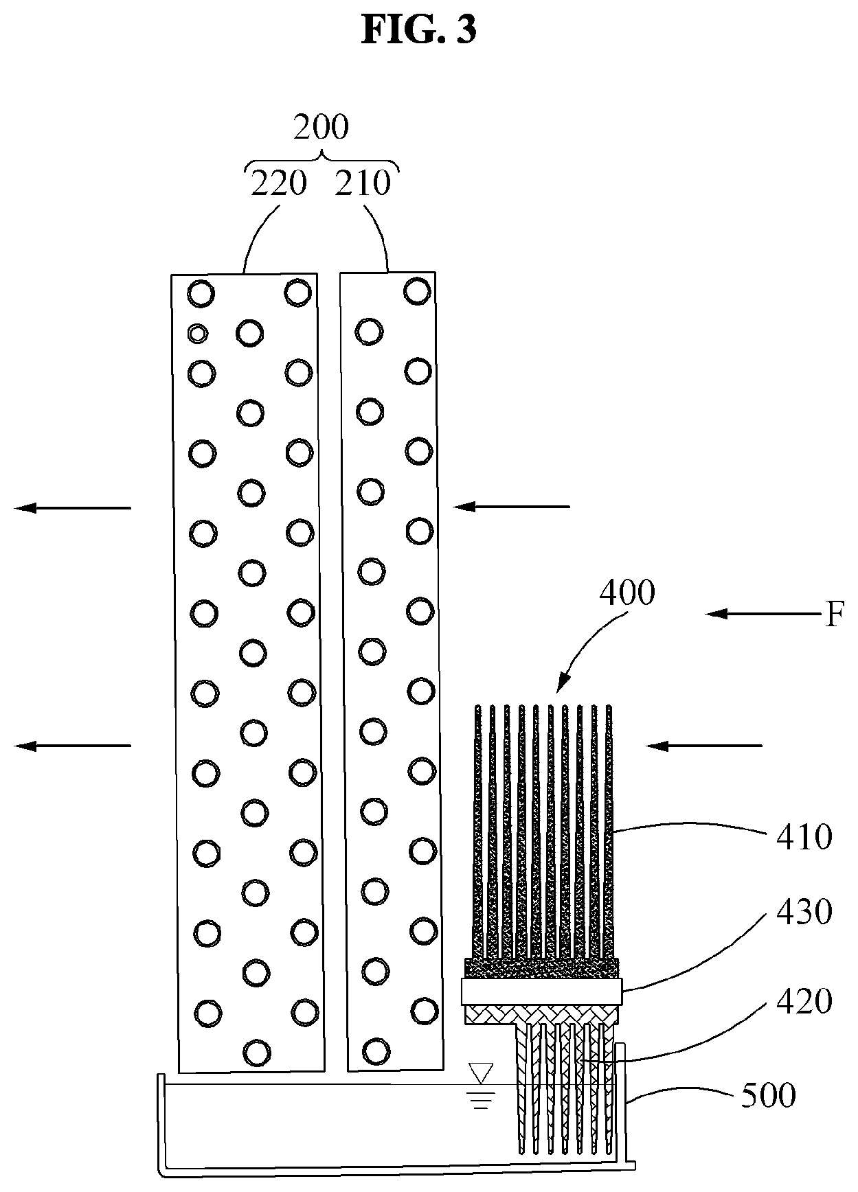
[0028] FIG. 3 is an enlarged view illustrating a part A of FIG. 2.
[0029] FIG. 4 illustrates another example of a dehumidifier viewed from side according to an example embodiment.
[0030] FIG. 5 is an enlarged view illustrating a part B of FIG. 4.
BEST MODE FOR CARRYING OUT THE INVENTION
[0031] Hereinafter, example embodiments will be described with reference to the accompanying drawings. The following description is provided according to some aspects of the example embodiments, and forms part of a detailed description of the example embodiments.
[0032] Also, descriptions of functions and constructions that are well known to one of ordinary skill in the art may be omitted for increased clarity and conciseness.
[0033] It should be understood that the terms used in the specification and the appended claims should not be construed as limited to general and dictionary meanings, but interpreted based on the meanings and concepts corresponding to technical aspects of a dehumidifier of the disclosure based on the principle that the inventor is allowed to define terms.
[0034] Accordingly, the description proposed herein is merely an example for the purpose of illustration, and is not intended to represent all technical aspects related to the hybrid powertrain apparatus of the disclosure, so it should be understood that other equivalents and modifications could be made thereto without departing from the spirit and scope of the disclosure.
[0035] FIG. 1 is a perspective view illustrating a dehumidifier according to an example embodiment. FIG. 2 illustrates an example of a dehumidifier viewed from side according to an example embodiment. FIG. 3 is an enlarged view illustrating a part A of FIG. 2. FIG. 4 illustrates another example of a dehumidifier viewed from side according to an example embodiment. FIG. 5 is an enlarged view illustrating a part B of FIG. 4.
[0036] Referring to FIGS. 1 and 2, a dehumidifier 10 may include a body 100 that suctions air through an inlet 110 and discharges the air through an outlet 120, a heat exchanger 200 that includes an evaporator 210 and a condenser 220 and removes moisture in the air suctioned through the inlet 110, a blower 300 that guides the air dehumidified in the heat exchanger 200 to the outlet 120, and a cooler 400 disposed between the inlet 110 and the heat exchanger 200. The cooler 400 may absorb heat from the suctioned air to reduce a temperature of the suctioned air.
[0037] The dehumidifier 10 may further include an accommodator 500 disposed below the heat exchanger 200 to collect a portion of dehumidification water falls from the heat exchanger 200, a compressor 600 disposed below the accommodator 500 to compress a gaseous refrigerant at a high temperature and a high pressure, and a water tank 700 detachably attached to the body 100 and located in a front part of the body 100. Dehumidification water generated in the evaporator 210 may be collected in the water tank 700.
[0038] Referring to FIG. 3, the cooler 400 may include a cooling element 410 that absorbs heat of air F suctioned through the inlet while the suctioned air is passing through the cooling element 410, and a heat dissipation element 420 disposed below the cooling element 410 to receive the heat absorbed by the cooling element 400 and dissipate the heat.
[0039] In addition, the cooler 400 may further include a Peltier element 430 disposed between the cooling element 410 and the heat dissipation element 420 to connect the cooling element 410 and the heat dissipation element 420 such that heat moves therebetween.
[0040] A lower end of the cooler 400 may be immersed in the dehumidification water collected in the accommodator 500. For example, a portion of the heat dissipation element 420 may be immersed in the dehumidification water collected in the accommodator 500.
[0041] The Peltier element 430 may be a thermoelement. When two different metals are in contact with each other with a contact point, a metal surface of one side may absorb heat and a metal surface of another side may release the heat in response to a direct current (DC) voltage being applied to both ends of the two metals.
[0042] In this example, the cooling element 410 connected to the metal surface absorbing the heat of the Peltier element 430 may absorb the hear from the air passing through the cooling element 410 to reduce the temperature of the air. Also, the heat dissipation element 420 connected to the metal surface releasing the heat of the Peltier element 430 may release the heat absorbed from the cooling element 410 to the dehumidification water collected in the accommodator 500.
[0043] An operation state of the dehumidifier 10 having the above structure will be explained in the following description.
[0044] In the dehumidifier 10, the inlet 110 may be formed in a rear surface of the body 100. However, a location of the inlet 110 is not limited thereto, and the inlet 110 may also be formed in a front surface of the body 100. Also, a replaceable filter may be attached to the inlet 110 to prevent foreign objects such as dust from entering the body 100.
[0045] The air F suctioned into the body 100 through the inlet 110 may be thermally dissipated by the cooling element 410 of the cooler 400 while passing through the cooler 400 disposed between the inlet 110 and the heat exchanger 200. Through this, the temperature of the air F suctioned into the body 100 may be reduced.
[0046] In this example, the heat absorbed by the cooling element 410 may be transmitted to the heat dissipation element 420 by the Peltier element 430. The heat dissipation element 420 may release the heat to the dehumidification water collected in the accommodator 500. A portion of the heat dissipation element 420 may be immersed in the cold dehumidification water of the accommodator 500 so as to allow more efficient heat dissipation.
[0047] As such, the dehumidifier 10 may reduce the temperature of the air F suctioned from an outside by arranging the cooler 400 to be between the inlet 110 and the heat exchanger 200. The temperature-reduced air may be cooled in the evaporator 210 so that condensate water is formed. Through this, the air may be dehumidified. While the dehumidified air is passing through the condenser 220, the temperature of the dehumidified air may increase. Thereafter, the dehumidified air may be guided by the blower 300 to the outlet 120, and then discharged to the outside. In this example, a portion of the dehumidification water condensed in the evaporator 210 may be collected in the accommodator 500 and a remaining portion of the dehumidification water may be collected in the water tank 700.
[0048] As described above, the dehumidifier 10 including the cooler 400 disposed between the inlet 110 and the heat exchanger 200 may reduce the temperature of the air F suctioned from the outside. Accordingly, a cooling efficiency in the evaporator 210 may be improved, and an overall dehumidification efficiency of the dehumidifier 10 may be improved.
[0049] Hereinafter, another example of the dehumidifier 10 will be described. For brevity, repeated description will be omitted.
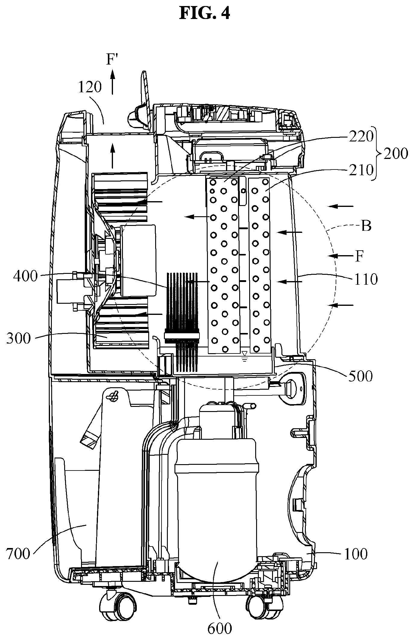
[0050] Referring to FIG. 4, a dehumidifier 10 may include a body 100 that suctions air through an inlet 110 and discharges the air through an outlet 120, a heat exchanger 200 that includes an evaporator 210 and a condenser 220 and removes moisture in the air suctioned through the inlet the inlet 110, a blower 300 that guides the air dehumidified in the heat exchanger 200 to the outlet 120, and a cooler 400 disposed between the heat exchanger 200 and the blower 300. The cooler 400 may absorb heat from suctioned or discharged air to reduce a temperature thereof. The dehumidifier 10 may further include the accommodator 500, the compressor 600, and the water tank 700 described herein.
[0051] Referring to FIG. 5, a humidity of the air may be reduced while the air is passing through the evaporator 210. Also, the temperature of the air may be increased while the air is passing through the condenser 220. Thereafter, the cooler 400 may reduce the temperature of the air.
[0052] In other words, high-temperature air dehumidified by the heat exchanger 200 may be thermally dissipated by the cooling element 410 of the cooler 400 while passing through the cooler 400 disposed between the heat exchanger 200 and the blower 300. Through this, a temperature of air F' discharged from the body 100 through the outlet 120 may be reduced.
[0053] In this example, the heat absorbed by the cooling element 410 may be transmitted to the heat dissipation element 420 by the Peltier element 430. The heat dissipation element 420 may release the heat to the dehumidification water collected in the accommodator 500.
[0054] As described above, the dehumidifier 10 including the cooler 400 disposed between the heat exchanger 200 and the blower 300 may reduce the temperature of the air F' discharged to the outside, thereby providing an environment in which a user feels comfortable.
[0055] While this disclosure includes specific examples, it will be apparent to one of ordinary skill in the art that various changes in form and details may be made in these examples without departing from the spirit and scope of the claims and their equivalents. The examples described herein are to be considered in a descriptive sense only, and not for purposes of limitation. Descriptions of features or aspects in each example are to be considered as being applicable to similar features or aspects in other examples. Therefore, the scope of the disclosure is defined not by the detailed description, but by the claims and their equivalents, and all variations within the scope of the claims and their equivalents are to be construed as being included in the disclosure.
* * * * *
D00000
D00001
D00002
D00003
D00004
D00005
XML
uspto.report is an independent third-party trademark research tool that is not affiliated, endorsed, or sponsored by the United States Patent and Trademark Office (USPTO) or any other governmental organization. The information provided by uspto.report is based on publicly available data at the time of writing and is intended for informational purposes only.
While we strive to provide accurate and up-to-date information, we do not guarantee the accuracy, completeness, reliability, or suitability of the information displayed on this site. The use of this site is at your own risk. Any reliance you place on such information is therefore strictly at your own risk.
All official trademark data, including owner information, should be verified by visiting the official USPTO website at www.uspto.gov. This site is not intended to replace professional legal advice and should not be used as a substitute for consulting with a legal professional who is knowledgeable about trademark law.