Decortication System And Process
Hefner; Corbett ; et al.
U.S. patent application number 16/013885 was filed with the patent office on 2019-12-26 for decortication system and process. This patent application is currently assigned to Power Zone Equipment Inc.. The applicant listed for this patent is Power Zone Equipment Inc.. Invention is credited to Robert Erickson, Gene Freeland, Eric Frey, Corbett Hefner, kok Chian Ng, Greg Sanchez, Cason Toews, Don Toews.
| Application Number | 20190390368 16/013885 |
| Document ID | / |
| Family ID | 68981021 |
| Filed Date | 2019-12-26 |


View All Diagrams
| United States Patent Application | 20190390368 |
| Kind Code | A1 |
| Hefner; Corbett ; et al. | December 26, 2019 |
DECORTICATION SYSTEM AND PROCESS
Abstract
A decortication system includes a feeder configured to convey unoriented fiber-bearing plant stalks in a bulk mass and a decorticator assembly comprising a multi-stage decorticator assembly. The decorticator assembly includes at least a first stage decorticator and a second stage decorticator arranged in series with one another. The first stage decorticator comprises a ripper that is configured to separate stalks from the bulk mass delivered by the feeder and to meter movement of stalks away from the ripper. The second stage decorticator is located downstream of the ripper and further decorticates the stalks to produce fiber and hurd that are separated from one another. It may comprise a roller-roller breaker assembly comprising plurality of roller-breaker assemblies located in series with one another. A third stage decorticator may be located downstream of the second stage decorticator and may comprise a second roller-breaker assembly.
| Inventors: | Hefner; Corbett; (Monte Vista, CO) ; Toews; Don; (Del Norte, CO) ; Toews; Cason; (Center, CO) ; Sanchez; Greg; (Saguache, CO) ; Ng; kok Chian; (Del Norte, CO) ; Freeland; Gene; (Center, CO) ; Frey; Eric; (Seguache, CO) ; Erickson; Robert; (Del Norte, CO) | ||||||||||
| Applicant: |
|
||||||||||
|---|---|---|---|---|---|---|---|---|---|---|---|
| Assignee: | Power Zone Equipment Inc. Center CO |
||||||||||
| Family ID: | 68981021 | ||||||||||
| Appl. No.: | 16/013885 | ||||||||||
| Filed: | June 20, 2018 |
| Current U.S. Class: | 1/1 |
| Current CPC Class: | D01B 1/28 20130101; D01B 1/14 20130101; D01B 1/32 20130101; D01B 1/46 20130101; D10B 2201/01 20130101; D10B 2201/06 20130101; D01B 1/40 20130101; D01B 1/38 20130101; D01B 1/22 20130101; D10B 2201/08 20130101; D01B 1/24 20130101; D01B 1/30 20130101; D01B 1/50 20130101; D01B 1/36 20130101 |
| International Class: | D01B 1/32 20060101 D01B001/32; D01B 1/22 20060101 D01B001/22; D01B 1/28 20060101 D01B001/28; D01B 1/46 20060101 D01B001/46; D01B 1/24 20060101 D01B001/24; D01B 1/40 20060101 D01B001/40; D01B 1/50 20060101 D01B001/50; D01B 1/38 20060101 D01B001/38; D01B 1/36 20060101 D01B001/36 |
Claims
1. A decortication system comprising: at least first and second stage decorticators located in series, the first stage decorticator comprising a ripper that configured to separate stalks from a bulk mass of unoriented fiber-bearing plants, to meter movement of stalks away from the ripper, and to partially decorticate the stalks, the second stage decorticator being located downstream from the first stage decorticator and being configured to further decorticate the stalks.
2. The decortication system as recited in claim 1, further comprising a feeder that is configured to convey the mass of bulk unoriented stalks to the first stage decorticator.
3. The decortication system as recited in claim 2, wherein the feeder comprises a feed conveyor assembly that comprises first and second laterally spaced, longitudinally extending conveyors capable of collectively transporting bales of unoriented stalks.
4. The decortication system as recited in claim 2, further comprising a driven accumulator that delivers bales to the feeder one at a time.
5. The decortication system as recited in claim 1, wherein the ripper comprises a vertically extending endless belt having an outer surface and laterally and longitudinally spaced protrusions that extend outwardly from the outer surface of the belt.
6. The decortication system as recited in claim 1, further comprising an air curtain generator located between the ripper and the second stage decorticator, the air curtain generator comprising a blower that blows stalks from the air curtain to the second stage decorticator while allowing denser objects to fall short of the second stage decorticator.
7. The decortication system as recited in claim 1, wherein the second stage decorticator comprises a roller-breaker assembly including a plurality of roller sets located in series with one another, wherein each of the roller sets has first and second spaced rotating rollers having a nip formed therebetween through which stalks are drawn.
8. The decortication system as recited in claim 7, further comprising a third stage decorticator located downstream from the second stage decorticator, the third stage decorticator comprising a second roller-breaker assembly including a plurality of roller sets arranged in series with one another.
9. The decortication system as recited in claim 8, wherein the first roller-breaker assembly comprises at least two roller sets.
10. The decortication system as recited in claim 9, wherein the first roller-breaker assembly further comprises at least one whipper that is located in series with the roller sets, the whipper having a rotating core and a plurality of flexible straps that extend outwardly from the rotating core and that are spaced axially and circumferentially of one another about the core.
11. The decortication system as recited in claim 8, wherein the second roller-breaker assembly comprises at least six roller sets.
12. The decortication system as recited in claim 11, wherein the second roller-breaker assembly comprises at least twelve roller sets.
13. The decortication system as recited in claim 7, further comprising variable frequency drives, each of which is configured to adjust a rotational speed of at least one roller set independently of at least one other roller set.
14. The decortication system as recited in claim 7, wherein nips of a plurality of upstream-most roller sets decrease in diameter from the upstream-most roller set of the plurality to the downstream-most roller set of the plurality.
15. The decortication system as recited in claim 7, further comprising a tensioning device that is configured to press the first and second rollers of each roller set together with an adjustable down pressure.
16. The decortication system as recited in claim 7, wherein the second stage decorticator comprises a frame having upper and lower sections on which the upper and lower rollers of each roller set are independently and removably mounted.
17. The decortication system as recited in claim 16, further comprising a powered actuator assembly that is configured to raise and lower the upper section of the frame relative to the lower section of the frame.
18. The decortication system as recited in claim 1, further comprising a screen assembly that is located downstream from the second stage decorticator and that is configured to further separate fiber from hurd.
19. The decortication system as recited in claim 18, wherein the screen comprises at least one trammel screen.
20. The decortication system as recited in claim 1, further comprising a wheeled trailer on which the feeder and the first and second stage decorticators are mounted for transport as a unit.
21. A decortication system comprising: (A) a mobile trailer having ground engaging wheels; (B) a feeder configured to convey unoriented fiber-bearing plant stalks in a bulk mass; (C) a first stage decorticator that is mounted on the trailer, the first stage decorticator comprising a ripper located adjacent a downstream end of the feeder, the ripper being configured to separate stalks from the mass and to meter movement of stalks away from the ripper and to partially decorticate the stalks; (D) a second stage decorticator that is mounted on the trailer downstream of the first stage decorticator in the direction of stalk movement through the system, the second stage decorticator comprising a roller-breaker assembly formed from a plurality of roller sets, each comprising first and second toothed rollers having a nip formed therebetween; and (E) an air curtain generator that is mounted on the trailer between the first and second stage decorticator, the air curtain generator being configured to generate an air stream of sufficient force to blow stalks toward the second stage decorticator from the first stage decorticator.
22. The decortication system as recited in claim 21, further comprising a third stage decorticator that is mounted on the trailer downstream of the second stage decorticator in the direction of stalk movement through the system, the third stage decorticator comprising a roller-breaker assembly formed from a plurality of roller sets, each comprising first and second toothed rollers having a nip formed therebetween, and further comprising a conveyor located between second and third stage decorticators.
23. A method comprising: (A) separating stalks from a bulk mass of unoriented stalks and conveying the separated stalks away from the bulk mass at a controlled volumetric rate; and (B) decorticating the separated stalks to produce fiber and hurd that are separated from one another.
24. The method as recited in claim 23, wherein the separating step is performed by an endless belt having protrusions extending from an outer surface thereof that strip stalks from the bulk mass, and wherein the belt performs a portion of the decorticating step.
25. The method as recited in claim 24, further comprising passing the separated stalks though an air curtain that blows stalks to a downstream decorticator stage while allowing dense objects to fall short of the downstream decorticator stage.
26. The method as recited in claim 23, wherein the bulk mass comprises a bale weighing at least 500 lbs.
27. The method as recited in claim 23, wherein the separating and decorticating steps are performed at a rate of at least 5 tons per hour.
28. The method as recited in claim 23, wherein at least 50% of the separated hurd is at least 0.5'' long.
29. The method as recited in claim 23, wherein the decorticating step is performed in at least two sequential stages, with the first stage being performed by a ripper that also performs the separating step and the second stage being performed by a roller-breaker assembly formed from a plurality of roller sets, each of which has first and second spaced rotating rollers having a nip formed therebetween through which stalks pass.
30. The method as recited in claim 29, wherein the second stage is performed by a first roller-breaker assembly, and further comprising performing a third stage of decortication using a second roller-breaker assembly located downstream from the first roller-breaker decorticator assembly.
31. The method as recited in claim 30, further comprising setting a rotational speed of the rollers of at least one roller set independently of the rollers of at least one other roller set.
32. The method as recited in claim 31, wherein speeds of a plurality of upstream-most roller sets increase progressively from the upstream-most roller set of the plurality to the downstream-most roller set of the plurality, thereby progressively orienting unoriented stalks passing therethrough.
33. The method as recited in claim 29, further comprising, in order to accommodate varying stalk characteristics, at least one of 1) adding additional roller sets to the roller-breaker decorticator, 2) removing roller sets from the roller-breaker decorticator, and 3) replacing rollers of roller sets having rollers of a first profile with roller sets of a second profile.
Description
BACKGROUND OF THE INVENTION
1. Field of the Invention
[0001] The invention relates generally to the decortication of plant stalks and, more particularly, relates a machine and process capable of rapidly obtaining fibers and hurd from bulk masses of unoriented plant stalks at high volumes and high rates.
2. Discussion of the Related Art
[0002] Decorticators, sometimes called decortication machines, have long been used for stripping the outer skin, bast fiber or rinds of stalks or stems of plants for various reasons. For example, decorticators are widely used to separate the outer fibrous layer from the inner hurd of stalks of hemp, ramie, flax, kenaf, or jute from the inner hurd of the stalk. Fibers obtained from the outer layers can then be used to make twine, rope, and textiles for myriad uses, and the inner hurd can be used, for example, as animal bedding.
[0003] Hand decortication was the only available method until the industrial revolution. The most commonly employed method was to strike the stalk of the plant with wood or stone to break it into pieces. Most early processes worked with straight stalk of plants that had been harvested, shocked or tied in bundles for drying, then allowed to dry in the open air. Once the plant was shocked, it could be move by hand to an area for storage and ultimately processing into fiber. Almost all the early decortication tools and machines were hand-powered.
[0004] The advent of mechanical power brought mechanical decortication with various degrees of success. Most of these machines included either a hammermill or a roller-breaker machine. A machine employing a hammermill is disclosed in U.S. Pat. No. 3,064,315 to Schneider. That machine separates the fibers from the hurd by forcefully hammering the stalks, generally pulverizing them. This hammering undesirably weakens the fibers. It also pulverizes the hurd into a generally powdery substance that is ill-suited for use as animal bedding. Hammermill-style decorticators also require that the stalks be retted in the field two-four weeks or even more prior to processing to break down the lignin and pectin that bind the fiber and the hurd together.
[0005] A roller-breaker machine is characterized by a system of mating toothed rollers sets that strip the outer fibrous layers from the hurd in a progressive fashion as the stalks are transferred though the machine. One such machine is disclosed in disclosed in U.S. Pat. No. 1,308,376 to Schlichten, the subject matter of which is incorporated herein by reference. These machines are gentler on the stalks than hammermills, producing stronger fibers. They also do not require as much retting as other processes and thus can handle relatively freshly-harvested stalks. However, roller-breaker decorticators such as the Schlichten machine have several limitations.
[0006] For example, currently known roller-breaker machines are only semi-automatic because the stalks must be manually fed into the machine in relatively small bundles of stalks that are one layer thick and oriented to extend lengthwise of the machine. This requirement lowers production rates to on the order of 1-3 tons per hour and increases labor costs.
[0007] In addition, previously-known roller-breaker decorticators, though, gentler on the stalks than hammermill-type decorticators, still generally pulverize the stalks and the attended hurd. The recovered hurd typically has a length of well less than 0.5''.
[0008] Still additionally, previously-known roller-breaker decorticators capable of operating on a scale of anything over a few hundred pounds per hour were not mobile.
[0009] Still further, previously-known roller-breaker decorticators could not be readily modified to handle different stalk characteristics.
[0010] The need therefore has arisen to provide a truly automated decorticating machine capable of processing unoriented stalks of fiber-bearing plants such as hemp, ramie, flax, kenaf, or jute.
[0011] The need additional has arisen to provide a decorticating machine capable of processing stalks at a rate exceeding 5 tons/hour.
[0012] The need additionally has arisen to provide a high-volume decorticating machine that is nevertheless mobile.
[0013] The need additionally has arisen to provide a decorticating machine that is readily configurable to accommodate different crop and/or environmental conditions.
[0014] The need additional has arisen to provide an improved method of decorticating stalks of fiber-bearing plants such as hemp, ramie, flax, kenaf, and jute.
SUMMARY OF THE INVENTION
[0015] In accordance with a first aspect of the invention, one or more of these needs is met by providing a decortication system comprising at least first and second stage decorticators arranged in series with one another. The first state decorticator comprises a ripper that is configured to separate stalks from a bulk mass of unoriented fiber-bearing plants to meter movement of stalks away from the bulk mass while initially decorticating the separated stalks. The second stage decorticator is located downstream of the ripper and further decorticates the stalks to produce fiber and hurd that are separated from one another.
[0016] A feeder such as a feed conveyor assembly may be configured to convey the mass of bulk unoriented stalks therealong. In this case, the feed conveyor assembly comprises first and second laterally spaced, longitudinally extending conveyors capable of collectively transporting bales of unoriented stalks.
[0017] In one possible configuration, the ripper comprises a vertically extending endless belt having an outer surface and laterally and longitudinally spaced protrusions that extend outwardly from the outer surface of the belt and that face the downstream end of the feeder.
[0018] An air curtain generator may be located between the ripper and the second stage decorticator. The air curtain generator may include a blower that blows stalks from the air curtain to the second stage decorticator while allowing denser objects to fall short of the second stage decorticator.
[0019] The second stage decorticator may include a roller-breaker assembly formed from a plurality of roller sets located in series with one another. Each roller set has first and second spaced rotating rollers having a nip formed therebetween through which stalks are drawn.
[0020] A third stage decorticator may be located downstream from the second stage decorticator and may comprise a roller-breaker assembly.
[0021] In one configuration, the system further includes variable frequency drives, each of which is configured to adjust a rotational speed of at least one roller set independently of at least one other roller set.
[0022] The roller sets may be provided in the form of self-contained modules permitting rapid change out of roller sets and/or the addition and/or removal of roller sets from the system.
[0023] In one configuration, at least one roller-breaker assembly comprises a frame having upper and lower sections on which the upper and lower rollers of each roller set are independently and removably mounted. In this case, a powered actuator may be configured to raise and lower the upper portion of the frame relative the lower portion of the frame.
[0024] The system, or at last major portions of it, may be mounted on a wheeled trailer for transport as a unit.
[0025] In accordance with another aspect of the invention, a decortication method comprises separating stalks from a bulk mass of unoriented stalks and conveying the separated stalks away from the bulk mass at a controlled volumetric rate, and decorticating the separated stalks to produce fiber and hurd that are separated from one another.
[0026] In one embodiment, the separating step is performed by an endless belt having protrusions extending from an outer surface thereof that strip stalks from the bulk mass, and the belt performs a portion of the decorticating step.
[0027] The method may additionally include passing the separated stalks though an air curtain that blows stalks to a downstream decorticator while allowing dense objects to fall short of the downstream decorticator.
[0028] The bulk mass may weigh at least 500 lbs., and the separating and decorticating steps are performed at a rate of at least 5 tons per hour.
[0029] The decorticating step may be performed in at least two sequential stages, with the first stage being performed by a ripper that also performs the separating step and the second stage being performed by a roller-breaker assembly formed from a plurality of roller sets, each of which has first and second spaced rotating rollers having a nip formed therebetween through which stalks pass. Further decortication may be performed by a second roller-breaker assembly located downstream from the first roller-breaker assembly.
[0030] In one configuration, the method additionally comprises, in order to accommodate varying stalk characteristics, at least one of 1) adding additional roller sets to the roller-breaker decorticator, 2) removing roller sets from the roller-breaker decorticator, and 3) replacing rollers of roller sets having rollers of a first profile with roller sets of a second profile.
[0031] These and other objects, advantages, and features of the invention will become apparent to those skilled in the art from the detailed description and the accompanying drawings. It should be understood, however, that the detailed description and accompanying drawings, while indicating preferred embodiments of the present invention, are given by way of illustration and not of limitation. Many changes and modifications may be made within the scope of the present invention without departing from the spirit thereof, and the invention includes all such modifications.
BRIEF DESCRIPTION OF THE DRAWINGS
[0032] Preferred exemplary embodiments of the invention are illustrated in the accompanying drawings, in which like reference numerals represent like parts throughout, and in which:
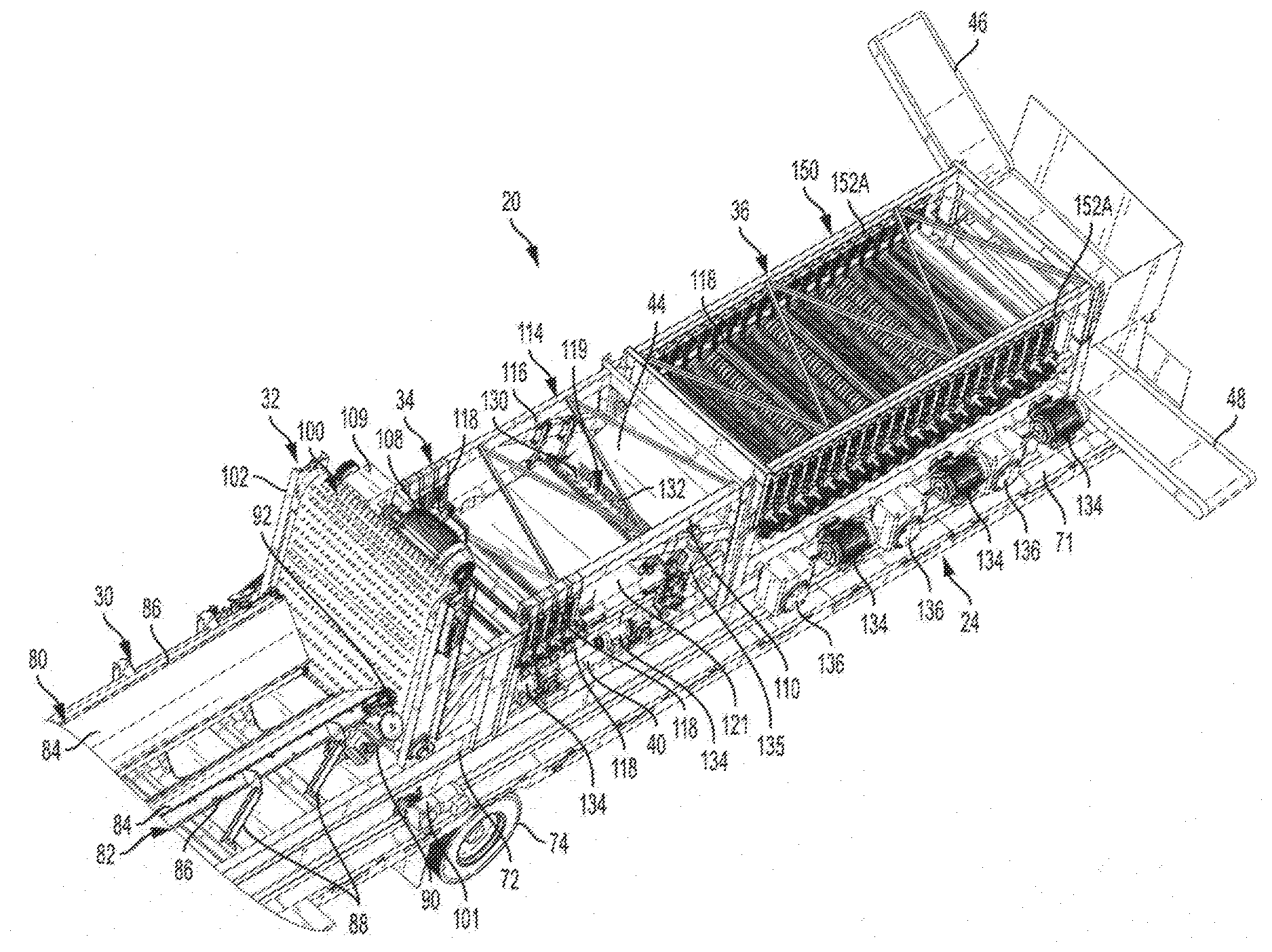
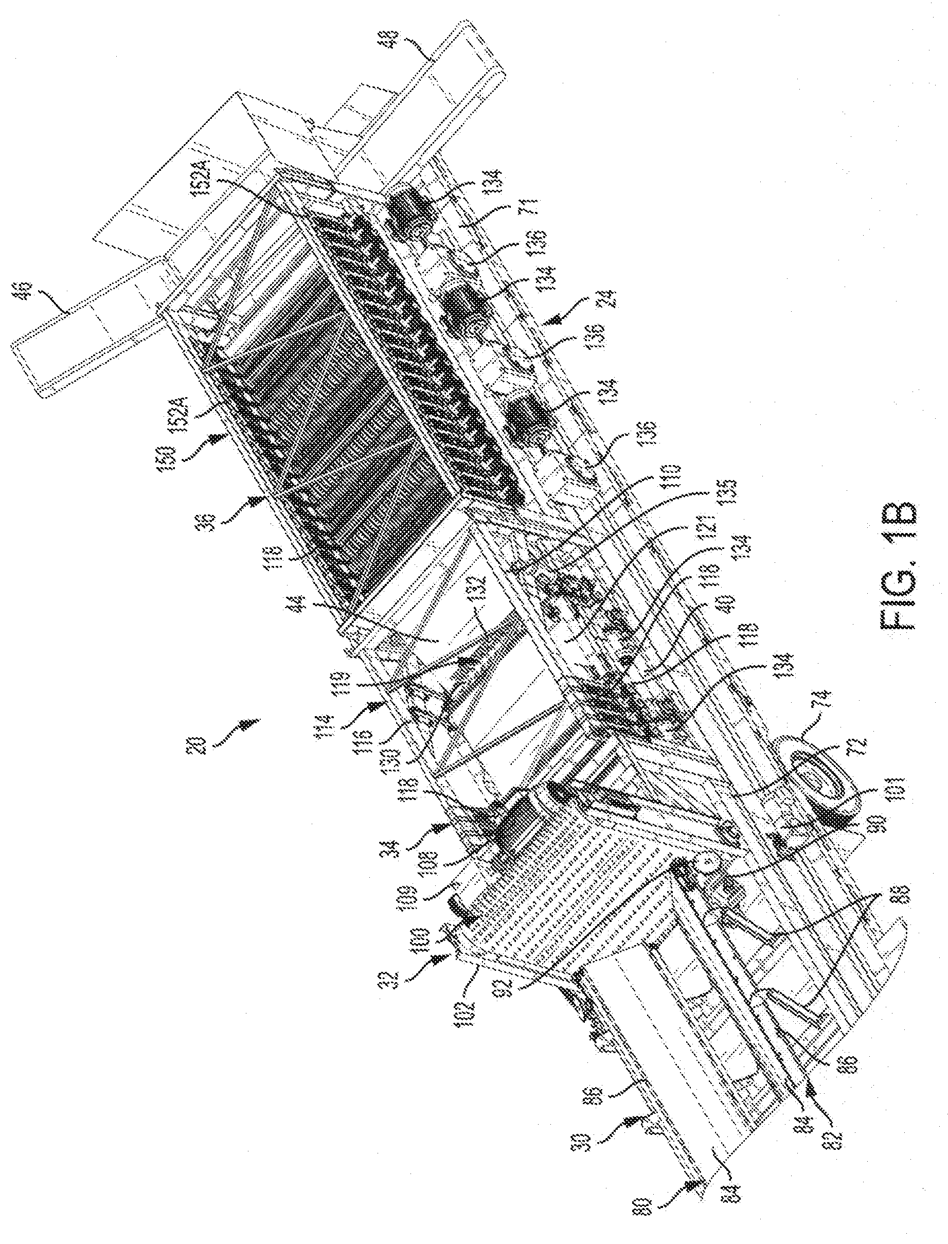
[0033] FIGS. 1A and 1B collectively form an isometric view of a decortication system constructed in accordance with the present invention;
[0034] FIG. 2 is a side elevation view of a portion of the decortication system of FIG. 1;
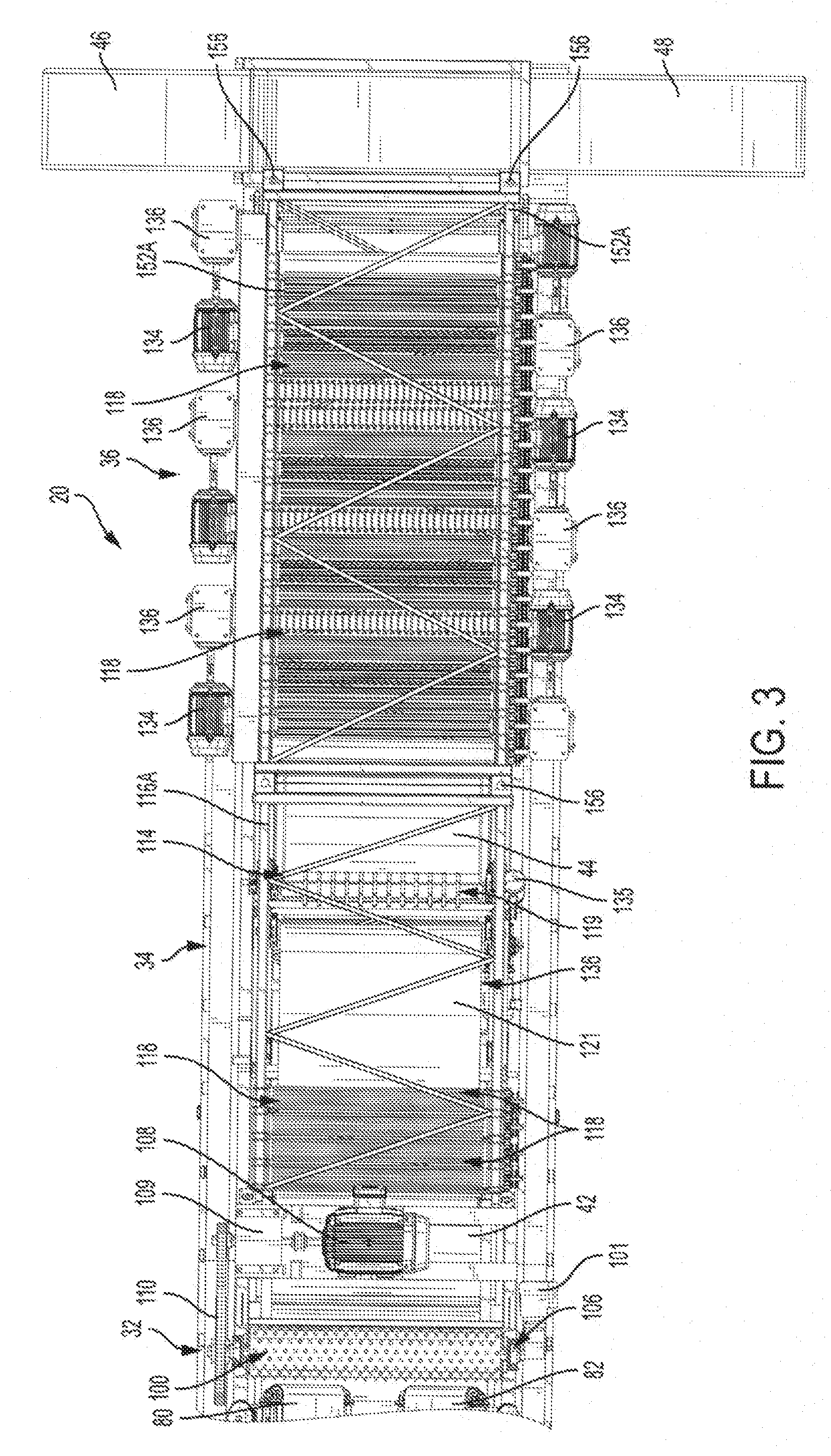
[0035] FIG. 3 is top plan view of the portion of the decortication system shown in FIG. 2;
[0036] FIG. 4 is a front-end elevation view of a ripper/first stage decorticator of the decortication system of FIG. 1;
[0037] FIG. 5 is a rear-end elevation view of the ripper/first stage decorticator and an air curtain generator of the decortication system of FIG. 1;
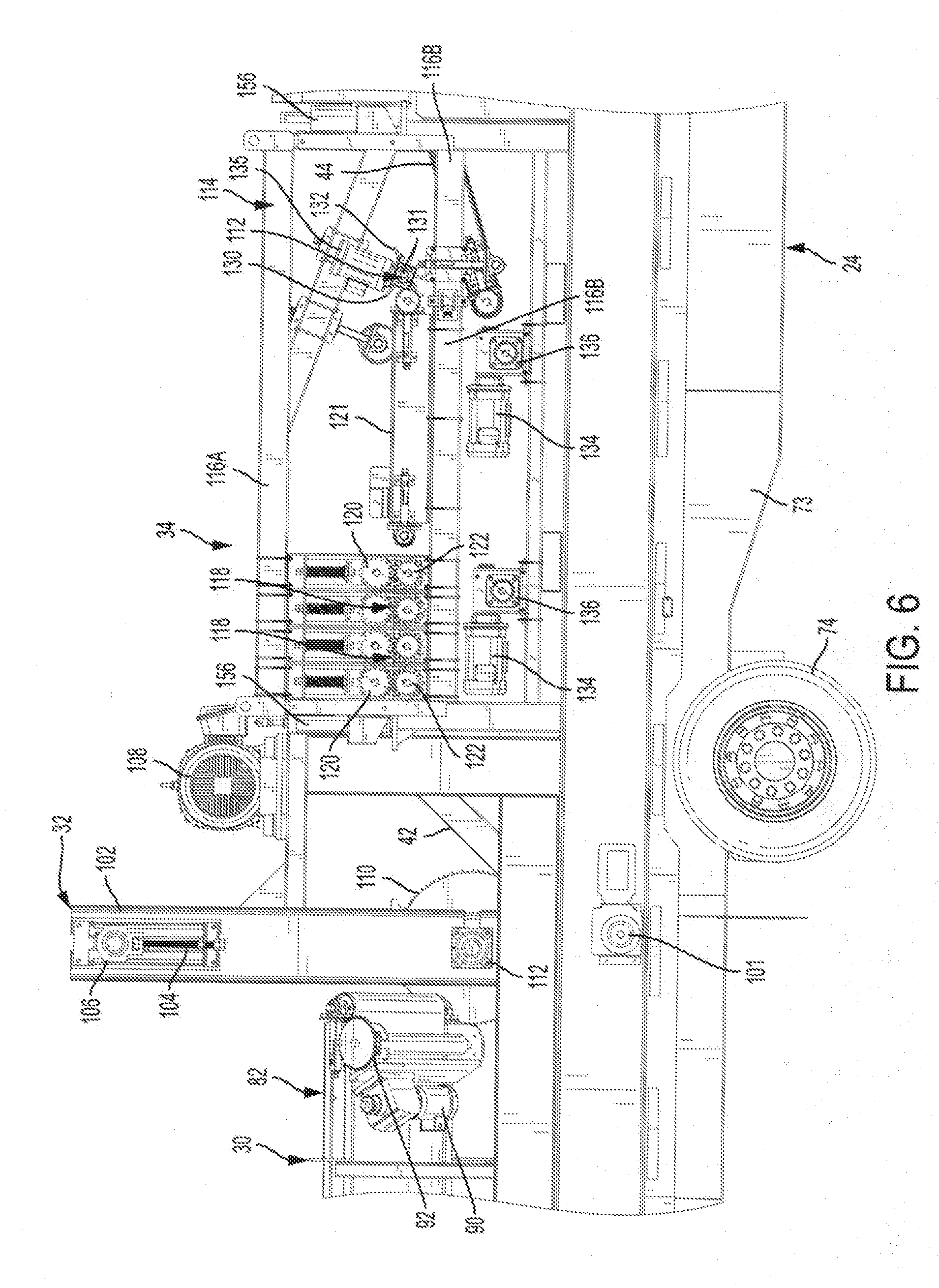
[0038] FIG. 6 is a side elevation view of the second stage decorticator/first roller-breaker assembly of the decortication system of FIG. 1;
[0039] FIG. 7 is top plan view a second stage decorticator/first roller-breaker assembly of the decortication system of FIG. 1;
[0040] FIG. 8 is side elevation view of the third stage decorticator/second roller-breaker assembly of the decortication system of FIG. 1;
[0041] FIG. 9 is a top plan view of the third stage decorticator/second roller-breaker decorticator assembly of FIG. 8;
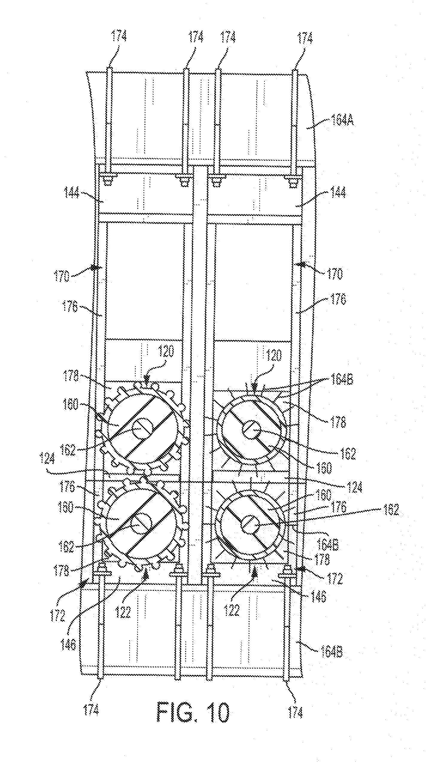
[0042] FIG. 10 is a sectional end view of two of the roller sets of the third stage decorticator/second roller-breaker assembly;
[0043] FIG. 11 is an exploded view of one of the roller sets of FIG. 10; and
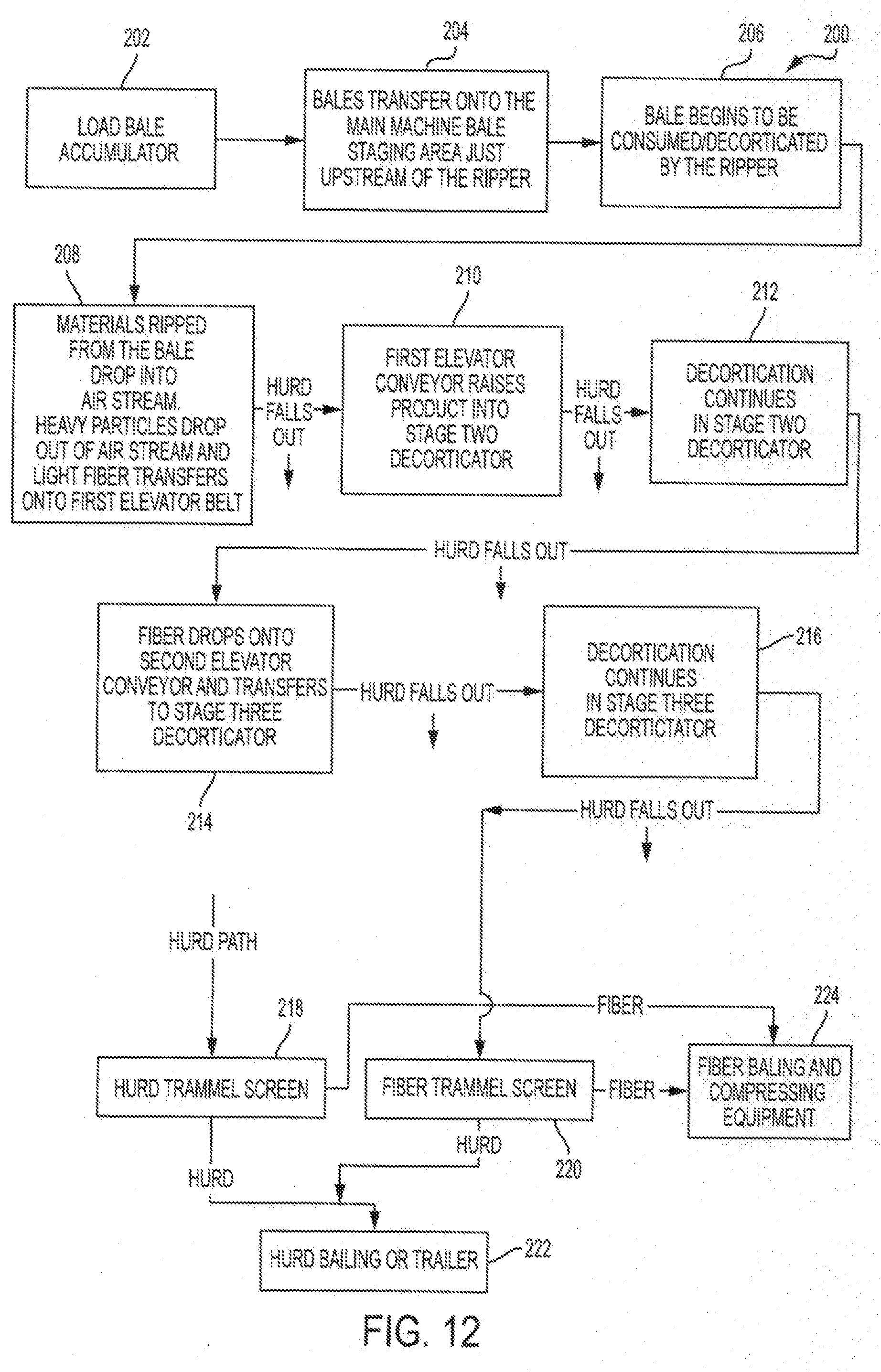
[0044] FIG. 12 is a functional schematic illustrating operation of the decortication system of FIG. 1.
DETAILED DESCRIPTION
[0045] Decorticating systems configured as described herein could be used to decorticate stalks of a wide variety of organic crop plants, including, but not limited to, ramie, flax, hemp, kenaf, and jute. The exemplary decorticating system illustrated in the figures and discussed below has several advantages, including. [0046] It is fully automated. [0047] It can handle unoriented stalks delivered to the machine in bulk masses such as large bales. [0048] It has a high capacity in excess of 5 tons per hour. [0049] It is extremely effective. [0050] It is mobile. [0051] It is versatile and modular.
[0052] Referring now to the drawings and initially to FIGS. 1A and 1B, a decorticating system or simply "decorticator" or "system" 20 constructed in accordance with an embodiment of the invention is illustrated. The system 20 is mounted on two trailers 22 and 24 arranged end-to-end and thus is fully mobile. Each trailer 22, 24 may be on the order of 40 feet to 55 feet long. Each trailer 22 or 24 may be expandable laterally to allow operators to walk around the equipment. In one embodiment, each trailer 22 or 24 is expandable from about 81/2 feet wide to about 121/2 feet wide. The first trailer 22 supports an accumulator 26 for receiving bulk masses of un-oriented stalks. The second trailer 24 supports, from upstream to downstream end, a feed conveyor assembly 30 and first, second, and third decorticator stages 32, 34, and 36. Also provided on the second trailer 24 are an air curtain generator 38 (FIG. 4), a hurd conveyor 40, first and second elevator conveyors 42 and 44 for transporting stalks from the first decorticator stage 32 to the second decorticator stage 34 and from the second decorticator stage 34 to the third decorticator stage 36, respectively, and fiber and hurd discharge conveyors 40 and 42. The three decorticator stages 32, 34, and 36 are configured to strip or separate stalks from a bale, orient the stalks at least to an extent, and progressively decorticate the stalks as they move through the system 20 to separate the outer fiber of the stalks from the inner hurd. The separated hurd and fibers are conveyed off the downstream end of the system 20 by respective discharge devices such as conveyors 46 and 48 and may be further processed, such as in trammel screens, as discussed below.
[0053] Referring to FIG. 1A, the first trailer 22 on which the accumulator 30 is mounted is a so called "goose neck" trailer that is about 40 feet long. The trailer 22 has a bed 50 and a pair of side rails 52. The side walls 52 extend longitudinally of the trailer 22 and are spaced from one another by generally the entire width of the trailer or about 5-6 feet in the present example. The bed 50 is mounted on a chassis 53 that is supported on wheels 54 and that can be towed by a hitch 56.
[0054] Still referring to FIG. 1A, the accumulator 26 is designed to receive several tons of unoriented stalks in bulk mases and to feed those bulk masses downstream to the feed conveyor assembly 30 on an on-demand basis. The illustrated accumulator 26 and feed conveyor assembly 30 are optimized to handle large square or round bales. Each bale typically weighs more than 500 pounds and more typically 800 to 1000 pounds or more. They are also quite large. In the case of square bales, each bale may be of the order of 6 feet to 8 feet long, deep, and high. Large round bales are of a similar size. The accumulator 26 is configured to hold 10 to 12 square or round bales loaded into the trailer 22 by a front-end loader or the like.
[0055] The accumulator 26 extends the entire length of the trailer 22 or on the order of 40 feet in the present embodiment. The accumulator 26 comprises a conveyor assembly 60 that includes first and second conveyors 62 and 64 that are spaced laterally from one another with a minimum spacing of about 5-6 feet. Each conveyor 62, 64 includes an endless belt 66 that is mounted on a frame 68. Each frame 68 is mounted on a number of spaced cross braces 70 that are mounted on top of the side rails 52 of the trailer 22. Each conveyor 62, 64 is inclined at an acute angle upwardly and outwardly from its bottom edge to its top edge. That angle may be 35.degree. to 60.degree. and, more typically, a 45.degree.. The bottom edge of each conveyor 62, 64 is positioned near the center of the trailer 22. Both belts 62 and 64 are driven by a common drive such as an electric motor (not shown). In operation, the belts 62 and 64 are driven in unison with one another to convey large bales stored on the accumulator 26 one at a time onto the feed conveyor assembly 30.
[0056] Referring to FIGS. 1A and 1B, the second trailer 24 is of similar construction to the first trailer 22. It may on the order of 50-55 feet long and may have an expandable width as discussed above in connection with the first trailer 22. It has a bed 71 and a pair of side rails 72 extending longitudinally of the trailer 24 and spaced from one another by generally the entire width of the trailer 24 or about 102 inches to 152 inches in the present example. The bed 71 is mounted on a chassis 73 that is supported on wheels 74 and that can be towed by a hitch (not shown) or in tandem with the first trailer 22.
[0057] Referring to FIGS. 1A, 1B and 2, the feed conveyor assembly 30 is located at the front or upstream end of the second trailer 24. It should be long enough to support at least one entire large bale and thus may be on the order of 6-10 feet long. It may be essentially identical in construction to the accumulator 26. It thus includes first and second laterally spaced inclined belt conveyors 80 and 82, each of which comprises a belt 84 mounted on a frame 86. The frame 86 is mounted on a number of cross supports 88 that are mounted on the side rails 72 of the trailer 24. The conveyors 80 and 82 are inclined at an angle that matches that of the accumulator conveyors 62, 64. As stated above, this angle of inclination may range from 30.degree. to 60.degree. and is more typically 45.degree.. The belts 84 are driven by an electric motor 90 and chain drive 92, seen in FIG. 1B. The motor 90 is controlled to deliver a bale to the first stage decorticator 32 at a rate at which the bale can be consumed by the first stage decorticator 32. That speed may be, for example, on the order of one bale every three minutes.
[0058] Referring to FIGS. 1B and 2-5, the first stage decorticator 32 is located adjacent the discharge end of the feed conveyor assembly 30. First stage decorticator 32 essentially acts as a large belt sander that performs several functions. First, it consumes bales received from the feed conveyor assembly 30 by ripping the top layers of unoriented stalks from the bale. It thus can be considered a "ripper", and the terms "ripper" and "first stage decorticator" are used synonymously herein. Second, it meters the feed rate and thickness of materials to the downstream components of the system 20. In addition, in tearing into the bale and stripping the top layers of stalks away from it, it begins the decortication process by breaking the stalks and stripping some of the fiber from the hurd. About 20-60%, and more typically, about 40-50%, of the total decortication process is performed by the first stage decorticator 32.
[0059] Still Referring to FIGS. 1B and 2-5, the first stage decorticator 32 of this embodiment comprises an endless vertically extending driven belt or "ripper belt" 100. (The terms "first stage decorticator" and "ripper" or "ripper belt" are used interchangeably herein, it being understood that the former term is generic and that the latter term describes a species of that genus.) The ripper belt 100 is spaced from the downstream ends of the feed conveyor assembly 30 by a relatively small gap of on the order of 1'' or less and, typically, on the order of the thickness of a typical stalk being processed by the system 20. That gap may be adjustable to accommodate prevailing stalk size by moving the feed conveyors 80, 82 and/or the ripper belt 100 toward or away from one another longitudinally of the second trailer 24. The belt 100 extends the width of the system 20. Belt 100 also is at least as high as the tallest bales contemplated to be handled by the system or, in the order of seven feet above the feed conveyor assembly 30 in the illustrated embodiment.
[0060] Still Referring to FIGS. 1B and 2-5, the ripper belt 100 is mounted on a frame 102 that, in turn, is mounted on the side rails 72 of the second trailer 24. Belt tension can be adjusted by operation of a threaded tensioning rod 104 acting against an upper guide pulley 106. The ripper belt 100 is driven by an electric motor 108 that is connected to a lower drive pulley 112 by a gearbox 109 and a chain drive 110 (FIGS. 4-5). The ripper belt 100 comprises a flexible membrane 115 formed by rubber or the like and a number of rigid protrusions 117 in the form of metal spikes, rods, or bolts extending outwardly from the outer surface of the membrane 115. The protrusions 117 extend outwardly from of the membrane 115 a sufficient distance to tear into and strip the outer layer of stalks from the adjacent bale. The protrusions may be on the order of 1/2'' to 1'' long and are laterally and longitudinally spaced from one another by 4'' or less. That spacing is 3'' in the illustrated embodiment. In use, the belt 100 acts generally like a belt sander and rips the outer layer of stalks from the bale while also tending to orientate the stalks so that they extend generally in parallel with the belt. It also strips some of the outer fibrous layer of each stalk from the inner hurd, initiating the decortication process.
[0061] Referring to FIG. 5, the air curtain generator 38 is located immediately downstream of the ripper belt 32 and upstream of the first elevator belt 42. It is located such that stalks that have been stripped and initially decorticated must fall through the air curtain generated by the generator 38. The air curtain generator 38 may, for example, comprise a number of electrically powered blowers. In the illustrated embodiment, 4 to 6 blowers are located at a common height beneath the bottom of the ripper belt 100 but above the bottom of the first elevator conveyor 42. The blowers are equally-spaced along the width of the system 20 and are spaced equidistantly across the width of the machine. These blowers collectively generate 6,000 to 10,000 CFM, and more typically 8000 CFM, of airflow and direct that airflow toward the first elevator conveyor 42. In operation, relatively light materials including the partially decorticated stalks and other organic materials are blown onto the downstream elevator conveyor 42 by the stream of air blown out of the air curtain generator 38, while denser articles such as bolts, rocks, etc. that may have been imbedded in the bales fall through the air stream to the ground without reaching the first elevator conveyor 42. Damage to the downstream components of the system 20 that otherwise could occur due to contact with these articles may therefore be avoided.
[0062] Referring to FIGS. 1B, 5, and 8, the hurd conveyor 40 is located just downstream of the air curtain generator 38 and beneath the remaining components of the system 20. The hurd conveyor 40 comprises an endless imperforate driven belt that extends horizontally and longitudinally of the system 20 from just downstream of the air curtain generator 38 all the way to the downstream end of the system 20. The belt is driven by an electric motor 101. In operation, hurd that is separated from the fibers in the various stages of the decorticating process is conveyed to the downstream end of the system 20 by the hurd conveyor 40 for discharge and further processing.
[0063] Referring to FIGS. 1B, 2, and 6, the first elevator conveyor 42 is located just downstream of the air curtain generator 38. Conveyor 42 comprises an endless belt having a lower end generally in line with the outlet of the air curtain generator 38 and an upper end positioned adjacent the inlet of the second stage decorticator 34. The belt of the conveyor is perforated to permit hurd that has been separated from the fibers by the ripper belt 100 to fall by gravity onto the underlying hurd conveyor 40.
[0064] Referring to FIGS. 3, 6, and 7, the second stage decorticator 34 of this embodiment comprises a first roller-breaker assembly that is configured to gradually break the fiber and allow the hurd to fall out. (The terms "second stage decorticator" and "first roller-breaker assembly" are used interchangeably herein, it being understood that the former term is generic and that the latter term describes a species of that genus.) The first roller-breaker assembly 34 comprises a plurality of roller sets 118 and may additionally comprise one or more rotating whippers 119, all of which are rotatably supported on longitudinally extending beams of upper and lower frames 116A and 116B of a frame assembly 114. Each roller set 118 comprises a pair of vertically spaced rollers 120 and 122 forming a nip 124 (FIG. 10) between them through which the stalks being decorticated are drawn in operation at least generally as described in the Schlichten patent. The roller sets 118 collectively function to break the stalks without pulverizing them and to further separate the outer fiber of the stalks from the inner hurd. The profiles of the various rollers 120, 122 may differ from one another, also as described in the Schlichten patent and as discussed in more detail below in conjunction with the third stage decorticator 36, to optimize this effect. Hence, the individual rollers 120, 122 could be profiled to perform specialized functions such as splitting and spreading, crushing and denting, breaking, combing, and softening, all of which are disclosed in the Schlichten patent. Additional characteristics of the roller sets 118, including their construction and the manner in which they are mounted on the frame, will be described below in conjunction with FIGS. 10 and 11. In the illustrated embodiment in which there is room within the footprint of the first roller breaker assembly 34 for additional roller sets, a horizontal conveyor 121 is provided for conveying materials from the downstream-most roller set 118 to the whipper 119. The belt of conveyor 121 may be perforated to allow hurd to fall through the belt onto the underlying hurd conveyor 40.
[0065] Still referring to FIGS. 3, 6, and 7, the whipper 119 comprises a rotating core or hub 130 and a number of flexible longitudinally and peripherally spaced straps 132 extending outwardly from the core 130. The core 130 is rotatably borne in a support 131 mounted on the upper frame 116 of the frame assembly 114. Two to Ten-inch long rubber straps 132 are provided in the illustrated embodiment. In operation, the straps 132 whip against the end of the conveyor 121 as the whipper 119 is driven to rotate from 200 to 2000 RPM, and more typically of about 300 to 600 RPM, to break the fiber open and further separate the fiber from the hurd.
[0066] It should be noted, that the modularity of roller sets 118 permits the ready addition of additional roller sets, the removal of one or more roller sets, or the replacement of roller set(s) of one type with roller set(s) of another type. Hence, while the illustrated embodiment comprises four roller sets 118 and one whipper 119 located at the downstream end of the first roller-breaker assembly 34, a whipper could be located at the upstream end of the first roller-breaker assembly 34 instead of or in addition to the illustrated downstream whipper. Whipper(s) also could be eliminated altogether, and more or fewer roller sets could be provided--all within the existing footprint of the system 20--simply by swapping out modular components.
[0067] Still referring to FIGS. 3, 6, and 7, The roller sets 118 are driven by one or more electric motors 134 and associated gear box(es) 136 and chain drive(s) as described in more detail below in conjunction with the second roller-breaker assembly forming the third stage decorticator 36. The illustrated embodiment has two electric motors 134 and associated gearboxes 136. A third motor 135 is provided for driving the whipper 119.
[0068] Materials exiting the first roller-breaker assembly 34 fall onto the second elevator conveyor 44 leading to the third stage decorticator 36. The second elevator conveyor 44 comprises an endless belt having a lower inlet end located beneath the outlet of the first roller-breaker assembly 34 and an upper outlet end positioned adjacent the inlet of the third stage decorticator 36. The conveyor 44 is perforated to permit hurd that has been separated from the fibers by the first roller-breaker assembly 34 to fall by gravity onto the underlying hurd conveyor 40.
[0069] Referring to FIGS. 3, 8, and 9, the third stage decorticator 36 comprises a second roller-breaker assembly formed from a plurality of roller sets 118 arranged in series as disclosed in the Schlichten patent. (The terms "third stage decorticator" and "second roller-breaker assembly" are used interchangeably herein, it being understood that the former term is generic and that the latter term describes a species of that genus.) The second roller-breaker assembly 36 functions in generally the same manner as the first roller-breaker assembly 34. However, it contains considerably more roller sets 118 while lacking any whippers (one or more whippers could be provided, if desired). The second roller-breaker assembly 36 may include more than six roller sets 118 and, more typically, more than ten roller sets 118 arranged in series with one another. The illustrated roller-breaker assembly 36 includes twenty roller sets 118 aligned with one another and mounted on a frame assembly 150 extending longitudinally of the second trailer 24. Referring to FIG. 9, the frame assembly 150 has separate upper and lower frames 152A and 152B including longitudinal beams that support the upper and lower rollers 120 and 122, respectively. Powered actuators 156 are provided for raising and lowering the upper frame 152A relative to the lower frame 152B to facilitate clearing of jams and maintenance and/or replacement of rollers. In the illustrated embodiment, four powered actuators 156 are provided, each of which is located adjacent to respective corner of the frame assembly 150. Each powered actuator comprises an electric screw jack in the illustrated embodiment. Alternatively, the powered actuators could comprise hydraulic cylinders or the like. The upper frame 116A of the frame assembly 114 of the first roller-breaker assembly can be raised and lowered relative to the lower frame 116B by similar powered actuators.
[0070] As with the rollers 120, 122 of the first roller-breaker assembly 34, of the rollers 120, 122 of each roller set 118 of the second roller-breaker assembly 36 can be customized for prevailing crop and environmental conditions. Referring briefly to FIGS. 10 and 11, each roller 120 or 122 comprises a hub or core 160 and a center shaft 162 extending all the way through the core 160 and protruding beyond both ends of the core 160. Peripherally-spaced, radially extending teeth 164A, 164B, etc. are provided on the outer surface of the core 160. In this embodiment, each roller 120, 122, as measured by the length of the core 160, is and 55'' long, and the diameter of each roller 120, 122, as measured from the outer surfaces of opposed teeth, is between 61/4'' and 7'', depending on the type of tooth provided on each roller 120, 122.
[0071] As discussed briefly above in conjunction with the first roller-breaker assembly 34, the outer teeth 164A, 164B, etc. of the rollers 120, 122 of each roller set 118 may be customized to achieve a desired function and to accommodate prevailing crop and environmental conditions. The teeth interact with the stalks to create a breaking deviation to separate the hurd from the fiber. Advantageously, however, all of the teeth of each roller 120, 122 of both roller-breaker assemblies 34 and 36 are generally relative rounded to avoid excessive shearing of materials being drawn through the nip between roller sets. For example, the teeth 164A, 164B, etc. may form from rods each having a radius of 1/4 inch to 5/8 inch. Some of these teeth, such as the teeth 164A of the crushing rollers, may "mesh" at the nips 124 in that the outer ends of teeth of the adjacent rollers may pass through the plane bisecting the nips 24, even though the teeth of the adjacent rollers may be axially offset from another to avoid interference between those teeth. The outer ends of the teeth of other rollers, such as the teeth 164B of the combing rollers, may be radially spaced from one another and from the plane bisecting the nips 124.
[0072] In one arrangement, the rollers 120 and 122 of the several upstream-most roller sets 118 of each of the roller-breaker assemblies 34 and 36 are spaced progressively closer together to effectively form a wedge with the nip 124 of each successive roller set being narrower than the nip 124 of the preceding roller set, such that the nips thereby forming a "wedge" of progressively decreasing diameter. The rollers 120 and 122 of each successive roller set 118 of this wedge also may be driven to rotate faster than the rollers of the preceding roller set 18, with the rollers 120 and 122 of the upstream-most roller set 118 being driven at a tangential speed that is at or slightly above the linear speed of the ripper belt 100. It has been found that this combination of features orients even highly unoriented stalks. This design also allows for processing larger stalk or bundle thicknesses than a traditional roller breaker lacking this combination of features. Experimentation has demonstrated the ability to process bundle thicknesses of 6-9 inches.
[0073] For example, in one arrangement in which the ripper belt 100 is driven at a speed of 100 feet per minute, the rollers 120 and 122 of the four upstream-most roller sets 118 of each of the roller-breaker assemblies 34 and 36 are arranged as per Table 1:
TABLE-US-00001 TABLE 1 UPSTREAM-MOST "WEDGE" ROLLER SET CHARACTERISTICS CAP TANTENTIAL BETWEEN ROLLER ROD TEETH SPEED ROLLER RADIUS AT NIP (FEET PER SET NO. (INCHES) (INCHES) MINUTE) 1 1/2 1/2 100 2 3/8 1/4 108 3 1/2 0 110 4 5/8 -1/4 122
[0074] Tests revealed that, when highly unoriented stalks are fed into the upstream end of a roller-breaker assembly with the four upstream-most roller sets 118 arranged as recited in TABLE 1, at least 50% of the stalks are oriented to within 25 deg. of the machine direction. In fact, at least 75%, and even at least 90%, achieve this high degree of orientation. This orienting effect of the "wedge" roller sets considerably improves performance of the remainder of the downstream roller sets.
[0075] All roller sets 118 could be driven by a single motor coupled to the roller sets by a drive chain assembly. However, the illustrated embodiment, multiple motors 134 are provided to permit independent control of at least some of the roller sets 118 relative to others of the roller sets. Each motor 134 is coupled to the associated roller set(s) 118 by a gearbox 136 and a flexible drive chain assembly 138. Six motors 134 are provided in the illustrated embodiment. In the configuration described above, alternating roller sets located downstream of these first four roller sets may be driven at different speeds that are higher and lower than the speed at which the downstream-most "wedge" roller set. The speed variation results in alternating tensioning and crushing of the stalks being drawn through the second roller-breaker assembly 36, further separating the fiber from the hurd. The speeds of the individual motors 134 also may be controllable from variable frequency drives that can be controlled to adjust roller speed to accommodate different crop conditions.
[0076] Referring to FIGS. 10 and 11, each roller set 118 takes the form of a self-contained module that that can be mounted on or removed from the roller-breaker assembly 34 or 36 as a unit. Each module consists of two laterally spaced upper supports 170 that collectively support the upper roller 120 and two laterally spaced lower supports 172 that collectively support the lower roller 122. Each support 170, 172 is mounted on a horizontal beam of the frame (116A or 1161 in the case of the first roller-breaker assembly 34 or 152A or 152B in the case of the second roller-breaker assembly 36) of the frame by a shackle system formed from four U-bolts 174. Each support 170, 172 comprises a frame 176 and a bearing block 178 that is located within the frame 176 and that has an aperture 180. The opposed ends of the drive shaft 162 of each of the rollers 120, 122 are borne in the respective support blocks 178 by bearing assemblies 182, 184, each of which is received in a respective aperture 180. A sprocket 186, 188 also is mounted on one end each the shaft 162 of each roller 120, 122 for driving the associated roller 120, 122 to rotate. An additional drive sprocket 190 is mounted on the shaft 162 of the lower roller 122 for connection to the drive chain assembly 138.
[0077] Still referring to FIGS. 10 and 11, the lower bearing blocks 178 of each roller set are fixed in position within their respective frames 176. Conversely, each of the upper bearing blocks 178 is movable along rails or grooves 192 in the associated frame 176. The upper bearing blocks 178 are biased along these grooves 192 towards the lower bearing blocks 176 so as to tension the upper and lower rollers 120 and 122 of each roller set 118 into engagement with one another. This biasing force can be set/adjusted by a pair of adjustable tensioning mechanisms located at the opposed ends the roller set 118. Each of the illustrated tensioning mechanism comprises a tensioning spring 194 located in the associated support 170 above the upper bearing block 178. Each spring 194 is mounted on threaded rod 196. The pretension in each spring 194 can be adjusted by adjusting the position of a nut 198 on the threaded rod 196. In more sophisticated embodiments, these springs could be replaced by electric screw jacks, pneumatic or hydraulic cylinders, or some other controllable power actuator.
[0078] It can thus be seen that each roller 120, 122 and its associated supports and tensioners form a self-contained unit mounted on the frame assembly 114 or 150 by a simple shackle system. Each roller 120, 122 and its associated components therefore can be readily removed as a unit and replaced with another roller having a different tooth profile. This high level of modularity renders the system 20 highly versatile, permitting it to be readily reconfigured to accommodate varying crop and/or environmental conditions.
[0079] The hurd conveyor 40 and the second roller-breaker assembly 36 are configured to convey the respective hurd and fiber streams away from the system 20 after the decortication system is complete. In some systems, processing is complete at this point. However, despite the fact that they are physically detached from one another, the hurd and fiber streams still may have significant percentages of fiber and hurd, respectively, mixed in them as they are discharged from the respective conveyors 48 and 46 because the hurd is prone to entangling in the fiber. If desired, further purification of these two streams can be performed by a screen or a system screens. For example, first and second trammel screens (shown only functionally schematically in FIG. 13) could be positioned downstream of the discharge conveyors 48 and 46, respectively. Each trammel screen could take the form of a rotating perforated drum that is inclined downwardly at an angle of 5.degree. to 8.degree. from the inlet to the outlet. Rotation of the inclined drum causes the materials being fed through it to tumble, whereupon hurd is separated from the fiber and falls through the perforations in the screen and the fiber ultimately is discharged from the downstream and of the drum. At the end of this process, the fiber can be at least 80, and more typically 90 to 95%, free of hurd and vice versa.
[0080] Operation of the system 20 now will be described with reference to FIG. 12 with general reference to FIGS. 1A-11. In preparation for the process, both trailers 22 and 24 of the system 20 are towed to a field or other location in which large square or round bales of a crop to be decorticated are stored. These bales may be formed, for example, from stalks of hemp, ramie, flax, kenaf, or jute. The trailers 22 and 24 are then positioned end-to end, and the motors 90, 108, 134, etc. and controller(s) are connected to an electrical power source. The process 200 now begins with the loading of the accumulator 26 with bales in Block 202. The accumulator conveyor 62 then conveys the bales one at a time to the feed conveyor assembly 30, which conveys the received bale to the bale staging area at the downstream end of the feed conveyor assembly 30 in Block 204. Then, in Block 206, the bale is progressively consumed and initially decorticated by the ripper forming the first stage decorticator 32. Materials ripped from the bale drop into the air stream generated by the curtain generator 38 in Block 208. Dense articles such as rocks, bolts, etc. drop through the air curtain and to the ground, while lighter materials, including whole stalks, fiber, and hurd are blown onto the first elevator conveyor 42. As mentioned above, the decortication process typically will be approximately 40 to 50% complete at this time.
[0081] The material blown onto the first elevator conveyor 42 then is conveyed to the second stage decorticator 34 formed by the first roller-breaker assembly in Block 210. Some of the separated hurd falls out of the perforated elevator conveyor 42 and onto the underlying hurd conveyor 40 at this time. Decortication continues in the second stage decorticator 34 in Block 212 with some of the separated hurd falling downwardly onto the hurd conveyor 40. The stalks are transferred to the third stage decorticator 36 by the second elevator conveyor 44 in Block 214, with some hurd falling through the perforations in the belt of the second elevator conveyor 44 and onto the hurd conveyor 40. The decortication process then is completed in the second roller-breaker assembly forming the third stage decorticator 36 in Block 216, with hurd falling out onto the hurd conveyor 40. The hurd and fiber streams are then discharged from system 20 by the respective conveyors 48 and 46 and may be further purified in respective trammel screens in Blocks 218 and 220 as described above. The hurd can then be baled or otherwise processed and Block 222, and the fiber can be baled, compressed or otherwise processed and Block 224.
[0082] This process can be performed at a rate of 5-10 tons per hour, with a large 800 to 1000 lb. bale being consumed approximately every three to six minutes. Since the decorticator stages 32, 34, and 36 do not chop or pummel the stalks, the fiber and hurd remain generally intact after the decortication process. For example, at 50%, and more typically at least 75%, of the separated hurd is at least 0.5'' long, and more typically at least 1'' long. The fibers also typically are more than 2.5'' to 3'' long.
[0083] While the invention is described herein in connection with specific embodiment(s), it will be understood it is not intended to limit the invention to these embodiment(s). On the contrary, it is intended to cover all alternatives, modifications and equivalents as may be included within the spirit and scope of the invention as defined by the appended claims. The scope of these and other changes will become apparent from the appended claims.
* * * * *
D00000
D00001
D00002
D00003
D00004
D00005
D00006
D00007
D00008
D00009
D00010
D00011
D00012

D00013
XML
uspto.report is an independent third-party trademark research tool that is not affiliated, endorsed, or sponsored by the United States Patent and Trademark Office (USPTO) or any other governmental organization. The information provided by uspto.report is based on publicly available data at the time of writing and is intended for informational purposes only.
While we strive to provide accurate and up-to-date information, we do not guarantee the accuracy, completeness, reliability, or suitability of the information displayed on this site. The use of this site is at your own risk. Any reliance you place on such information is therefore strictly at your own risk.
All official trademark data, including owner information, should be verified by visiting the official USPTO website at www.uspto.gov. This site is not intended to replace professional legal advice and should not be used as a substitute for consulting with a legal professional who is knowledgeable about trademark law.