Substrate Processing System
Min; YoonKi ; et al.
U.S. patent application number 16/445096 was filed with the patent office on 2019-12-26 for substrate processing system. The applicant listed for this patent is ASM IP Holding B.V.. Invention is credited to SeungJu Chun, YoungHoon Kim, HakJoo Lee, YoonKi Min.
| Application Number | 20190390343 16/445096 |
| Document ID | / |
| Family ID | 68968854 |
| Filed Date | 2019-12-26 |

| United States Patent Application | 20190390343 |
| Kind Code | A1 |
| Min; YoonKi ; et al. | December 26, 2019 |
SUBSTRATE PROCESSING SYSTEM
Abstract
Provided is a substrate processing system for improving productivity of processes. In this regard, the substrate processing system includes: a first chamber providing a space where at least one substrate is accommodated; a second chamber configured to transfer at least one substrate to the first chamber; and a temperature control unit configured to change a temperature of a gas in the second chamber.
| Inventors: | Min; YoonKi; (Seoul, KR) ; Kim; YoungHoon; (Cheonan-si, KR) ; Lee; HakJoo; (Pyeongtaek-si, KR) ; Chun; SeungJu; (Cheonan-si, KR) | ||||||||||
| Applicant: |
|
||||||||||
|---|---|---|---|---|---|---|---|---|---|---|---|
| Family ID: | 68968854 | ||||||||||
| Appl. No.: | 16/445096 | ||||||||||
| Filed: | June 18, 2019 |
| Current U.S. Class: | 1/1 |
| Current CPC Class: | H01L 21/67248 20130101; C23C 16/46 20130101; H01L 21/67703 20130101; C23C 16/52 20130101; C23C 16/54 20130101; H01L 21/67109 20130101; C23C 14/566 20130101; H01J 37/3244 20130101; H01L 21/67196 20130101; H01J 37/32522 20130101; H01J 37/32743 20130101 |
| International Class: | C23C 16/46 20060101 C23C016/46; H01L 21/67 20060101 H01L021/67; C23C 16/52 20060101 C23C016/52; H01L 21/677 20060101 H01L021/677 |
Foreign Application Data
| Date | Code | Application Number |
|---|---|---|
| Jun 21, 2018 | KR | 10-2018-0071696 |
Claims
1. A substrate processing system comprising: a reaction chamber providing a space where at least one substrate is processed; a substrate transfer chamber configured to supply at least one substrate to the reaction chamber; and at least one heater configured to heat a gas supplied to the substrate transfer chamber, wherein, when the reaction chamber and the substrate transfer chamber communicate with each other, pressure of a gas of the substrate transfer chamber is equal to or higher than pressure of a gas of the reaction chamber.
2. The substrate processing system of claim 1, wherein the at least one heater is arranged at the substrate transfer chamber, and accordingly, a gas inside the substrate transfer chamber is heated.
3. The substrate processing system of claim 1, further comprising a protective cover configured to block heat radiated from the at least one heater.
4. The substrate processing system of claim 3, wherein the protective cover is arranged between the substrate transfer chamber and the reaction chamber.
5. The substrate processing system of claim 1, further comprising a gas supply line connected to the substrate transfer chamber.
6. The substrate processing system of claim 5, wherein the at least one heater is arranged at the gas supply line, and accordingly, a gas passing through the substrate supply line is heated.
7. The substrate processing system of claim 5, wherein the at least one heater comprises: a first heater arranged at the gas supply line; and a second heater arranged at the substrate transfer chamber.
8. The substrate processing system of claim 7, wherein the first heater and the second heater are independently heated.
9. The substrate processing system of claim 7, wherein a first heating temperature of the first heater is equal to or higher than a second heating temperature of the second heater.
10. The substrate processing system of claim 1, further comprising a substrate transfer unit arranged at the substrate transfer chamber, wherein the substrate transfer unit comprises a cooling member.
11. The substrate processing system of claim 1, wherein a temperature of the gas heated by the at least one heater is equal to or higher than an internal temperature of the reaction chamber.
12. The substrate processing system of claim 11, wherein, when a substrate is introduced from the substrate transfer chamber to the reaction chamber, the temperature of the gas heated by the at least one heater is higher than the internal temperature of the reaction chamber.
13. The substrate processing system of claim 1, wherein the at least one heater is further configured to heat the gas before a substrate is introduced to the reaction chamber.
14. The substrate processing system of claim 1, wherein the at least one heater is further configured to heat the gas before a substrate is discharged from the reaction chamber.
15. The substrate processing system of claim 1, wherein at least some of the gas heated by the at least one heater is introduced from the substrate transfer chamber to the reaction chamber.
16. A substrate processing system comprising: a first chamber providing a space where at least one substrate is accommodated; a second chamber configured to transfer at least one substrate to the first chamber; and a temperature control unit configured to change a temperature of a gas in the second chamber.
17. The substrate processing system of claim 16, wherein the gas having the temperature changed by the temperature control unit is introduced from the second chamber to the first chamber.
18. The substrate processing system of claim 1, further comprising a third chamber providing a space where at least one substrate is accommodated, wherein the temperature control unit is further configured to, when at least one substrate is moved from the first chamber to the third chamber, change a temperature of a gas in the second chamber to correspond to a temperature condition of the third chamber.
19. A substrate processing system comprising: a load lock chamber configured to accommodate at least one substrate; a reaction chamber providing a space where at least one substrate is processed; a substrate transfer chamber configured to transfer at least one substrate between the load lock chamber and the reaction chamber; a gas supplier configured to supply a gas to the substrate transfer chamber; a gas supply line connecting the gas supplier and the substrate transfer chamber; and at least one heater arranged at at least one of the gas supplier, the substrate transfer chamber, and the gas supply line, and configured to heat the gas, wherein, when the reaction chamber and the substrate transfer chamber communicate, at least some of the gas heated by the at least one heater is introduced from the substrate transfer chamber to the reaction chamber, and the at least one heater is further configured to heat the gas before at least one substrate is introduced to the reaction chamber and before at least one substrate is discharged from the reaction chamber.
20. The substrate processing system of claim 19, further comprising a protective cover arranged between the substrate transfer chamber and the load lock chamber and configured to block heat radiated from the at least one heater.
Description
CROSS-REFERENCE TO RELATED APPLICATION
[0001] This application claims the benefit of Korean Patent Application No. 10-2018-0071696, filed on Jun. 21, 2018, in the Korean Intellectual Property Office, the disclosure of which is incorporated herein in its entirety by reference.
BACKGROUND
1. Field
[0002] One or more embodiments relate to a substrate processing system, and more particularly, to a substrate processing system providing improved productivity.
2. Description of the Related Art
[0003] During a high-temperature process, a substrate is loaded into a reactor, and then has a substrate temperature stabilization time (preheat time) for a certain period of time. During the substrate temperature stabilization time, a substrate temperature reaches a process temperature, and then stable substrate processing processes, such as deposition, etching, and cleaning, are performed. Since a temperature of the substrate is an important process variable in the substrate processing processes, it is important to set a suitable substrate temperature stabilization time.
[0004] In detail, when the substrate processing processes are performed while the substrate temperature is not stabilized, the substrate processing processes are not smooth and a defect ratio of semiconductor devices increases. For example, when the deposition is not performed at a suitable temperature, it is difficult to deposit a thin film having desired film quality.
[0005] As such, a substrate temperature stabilization period is required for smooth substrate processing, but on the other hand, productivity per time may be decreased. Accordingly, it is important to secure a time period for stabilization of the temperature of the substrate while reducing an effect on the substrate processing so as to improve productivity.
SUMMARY
[0006] One or more embodiments include a substrate processing system capable of improving productivity per time while securing stability of processes, by quickly securing a substrate temperature stabilization period for smooth substrate processing.
[0007] Additional aspects will be set forth in part in the description which follows and, in part, will be apparent from the description, or may be learned by practice of the presented embodiments.
[0008] According to one or more embodiments, a substrate processing system includes: a reaction chamber providing a space where at least one substrate is processed; a substrate transfer chamber configured to supply at least one substrate to the reaction chamber; and at least one heater configured to heat a gas supplied to the substrate transfer chamber, wherein, when the reaction chamber and the substrate transfer chamber communicate with each other, pressure of a gas of the substrate transfer chamber is equal to or higher than pressure of a gas of the reaction chamber.
[0009] The at least one heater may be arranged at the substrate transfer chamber, and accordingly, a gas inside the substrate transfer chamber may be heated.
[0010] The substrate processing system may further include a protective cover configured to block heat radiated from the at least one heater. In this case, the protective cover may be arranged between the substrate transfer chamber and the reaction chamber.
[0011] The substrate processing system may further include a gas supply line connected to the substrate transfer chamber. The at least one heater may be arranged at the gas supply line, and accordingly, a gas passing through the substrate supply line may be heated.
[0012] The at least one heater may include: a first heater arranged at the gas supply line; and a second heater arranged at the substrate transfer chamber. The first heater and the second heater may be independently heated. A first heating temperature of the first heater may be equal to or higher than a second heating temperature of the second heater.
[0013] The substrate processing system may further include a substrate transfer unit arranged at the substrate transfer chamber, wherein the substrate transfer unit may include a cooling member.
[0014] A temperature of the gas heated by the at least one heater may be equal to or higher than an internal temperature of the reaction chamber.
[0015] When a substrate is introduced from the substrate transfer chamber to the reaction chamber, the temperature of the gas heated by the at least one heater may be higher than the internal temperature of the reaction chamber.
[0016] The at least one heater may be further configured to heat the gas before a substrate is introduced to the reaction chamber. The at least one heater may be further configured to heat the gas before a substrate is discharged from the reaction chamber.
[0017] At least some of the gas heated by the at least one heater may be introduced from the substrate transfer chamber to the reaction chamber.
[0018] According to one or more embodiments, a substrate processing system includes: a first chamber providing a space where at least one substrate is accommodated; a second chamber configured to transfer at least one substrate to the first chamber; and a temperature control unit configured to change a temperature of a gas in the second chamber.
[0019] The gas having the temperature changed by the temperature control unit may be introduced from the second chamber to the first chamber.
[0020] The substrate processing system may further include a third chamber providing a space where at least one substrate is accommodated, wherein the temperature control unit may be further configured to, when at least one substrate is moved from the first chamber to the third chamber, change a temperature of a gas in the second chamber to correspond to a temperature condition of the third chamber.
[0021] According to one or more embodiments, a substrate processing system includes: a load lock chamber configured to accommodate at least one substrate; a reaction chamber providing a space where at least one substrate is processed; a substrate transfer chamber configured to transfer at least one substrate between the load lock chamber and the reaction chamber; a gas supplier configured to supply a gas to the substrate transfer chamber; a gas supply line connecting the gas supplier and the substrate transfer chamber; and at least one heater arranged at at least one of the gas supplier, the substrate transfer chamber, and the gas supply line, and configured to heat the gas, wherein, when the reaction chamber and the substrate transfer chamber communicate, at least some of the gas heated by the at least one heater is introduced from the substrate transfer chamber to the reaction chamber, and the at least one heater is further configured to heat the gas before at least one substrate is introduced to the reaction chamber and before at least one substrate is discharged from the reaction chamber.
[0022] The substrate processing system may further include a protective cover arranged between the substrate transfer chamber and the load lock chamber and configured to block heat radiated from the at least one heater.
BRIEF DESCRIPTION OF THE DRAWINGS
[0023] These and/or other aspects will become apparent and more readily appreciated from the following description of the embodiments, taken in conjunction with the accompanying drawings in which:
[0024] FIG. 1 is a diagram of a substrate processing system according to embodiments of the present disclosure;
[0025] FIG. 2 shows a change in a temperature of a substrate support after a substrate is loaded onto the substrate support;
[0026] FIGS. 3 and 4 are cross-sectional views of a substrate processing system according to other embodiments of the present disclosure; and
[0027] FIG. 5 is a flowchart of a substrate processing method according to an embodiment of the present disclosure.
DETAILED DESCRIPTION
[0028] Hereinafter, one or more embodiments of the present disclosure are described with reference to accompanying drawings.
[0029] This disclosure may, however, be embodied in many different forms and should not be construed as limited to the exemplary embodiments set forth herein. Rather, these embodiments are provided so that this disclosure will be thorough and complete, and will fully convey the scope of the disclosure to those of ordinary skill in the art.
[0030] The terms used in the present specification are merely used to describe particular embodiments, and are not intended to limit the present disclosure. An expression used in the singular encompasses the expression of the plural, unless it has a clearly different meaning in the context. In the present specification, it is to be understood that the terms such as "including" or "having," etc., are intended to indicate the existence of the features, numbers, steps, actions, components, parts, or combinations thereof disclosed in the specification, and are not intended to preclude the possibility that one or more other features, numbers, steps, actions, components, parts, or combinations thereof may exist or may be added. As used herein, the term "and/or" includes any and all combinations of one or more of the associated listed items. Expressions such as "at least one of," when preceding a list of elements, modify the entire list of elements and do not modify the individual elements of the list.
[0031] It will be understood that, although the terms `first`, `second`, etc., may be used herein to describe various elements, components, regions, layers and/or sections, these elements, components, regions, layers and/or sections should not be limited by these terms. These terms do not denote a certain order, top and bottom, or superiority and inferiority, but are only used to distinguish one element, component, region, layer or section from another region, layer or section. Thus, a first element, component, region, layer or section discussed below could be termed a second element, component, region, layer or section without departing from the teachings of the present disclosure.
[0032] In the present disclosure, a "gas" may include an evaporated solid and/or a liquid and may consist of a single gas or a mixture of gases. In the present disclosure, a process gas introduced to a reaction chamber through a gas supply unit may include a precursor gas and an additive gas. The precursor gas and the additive gas may be typically introduced into a reaction space as a mixed gas or separately. The precursor gas may be introduced together with a carrier gas, such as an inert gas. The additive gas may include a dilute gas, such as a reactant gas and an inert gas. The reactant gas and the dilute gas may be introduced into a reaction space after being mixed or separately. A precursor may consist of at least two precursors, and the reactant gas may consist of at least two reactant gases. The precursor is chemically adsorbed onto a substrate and is a gas containing a metalloid or a metal element that typically has a main structure of a matrix of a dielectric film. The reactant gas for deposition is a gas reacting with the precursor chemically adsorbed onto the substrate when the gas is excited to anchor an atomic layer or monolayer on the substrate. "Chemisorption" denotes chemical saturation absorption. A gas other than the process gas, i.e., a gas introduced without passing through the gas supply unit, may be used to seal the reaction space, and such a gas may include a seal gas, such as an insert gas. According to some embodiments, a "film" denotes a layer continuously extending in a direction perpendicular to a thickness direction without pin holes so as to cover an entire target or a related surface, or a layer simply covering a target or a related surface. According to some embodiments, a "layer" denotes a structure having a certain thickness formed on a surface, a synonym of a film, or a non-film structure. A film or layer may include a discontinuous single film or layer, or multiple films or layers having certain properties, may have clear or unclear boundaries between adjacent films or layers, and may be set based on physical, chemical, and/or other properties, formation processes or sequences, and/or functions or purposes of adjacent films or layers.
[0033] In the present disclosure, the expression "same material" should be interpreted that main components are the same. For example, when a first layer and a second layer are both a silicon nitride layer and are formed of a same material, a main component of the first layer may be selected from the group consisting of Si.sub.2N, SiN, Si.sub.3N.sub.4, and Si.sub.2N.sub.3, and a main component of the second layer may also be selected from the group, but a detailed property may be different from that of the first layer.
[0034] In addition, in the present disclosure, any two variables may constitute an operable range of the variables based on the fact that the operable range may be determined based on routine operations, and a certain indicated range may include or exclude end points. In addition, values of certain indicated variables (regardless of whether the values are indicated by "about") may denote accurate values or approximate values, may include equivalents, and in some embodiments, may denote an average value, a median value, a representative value, a multiple value, etc.
[0035] In the present disclosure where conditions and/or structures are not specified, one of ordinary skill in the art may easily provide the conditions and/or structures in the viewpoint of the present disclosure as a matter of routine experiments. In all embodiments, any component used in one embodiment includes those explicitly, necessarily, or essentially disclosed herein for intended purposes, and thus may be replaced by any equivalent component. In addition, the present disclosure may be equally applied to apparatuses and methods.
[0036] Embodiments of the present disclosure are described with reference to drawings schematically illustrating the embodiments. As such, variations from the shapes of the illustrations as a result, for example, of manufacturing techniques and/or tolerances, are to be expected. Thus, embodiments of the present disclosure should not be construed as limited to the particular shapes of regions illustrated herein but are to include deviations in shapes that result, for example, from manufacturing.
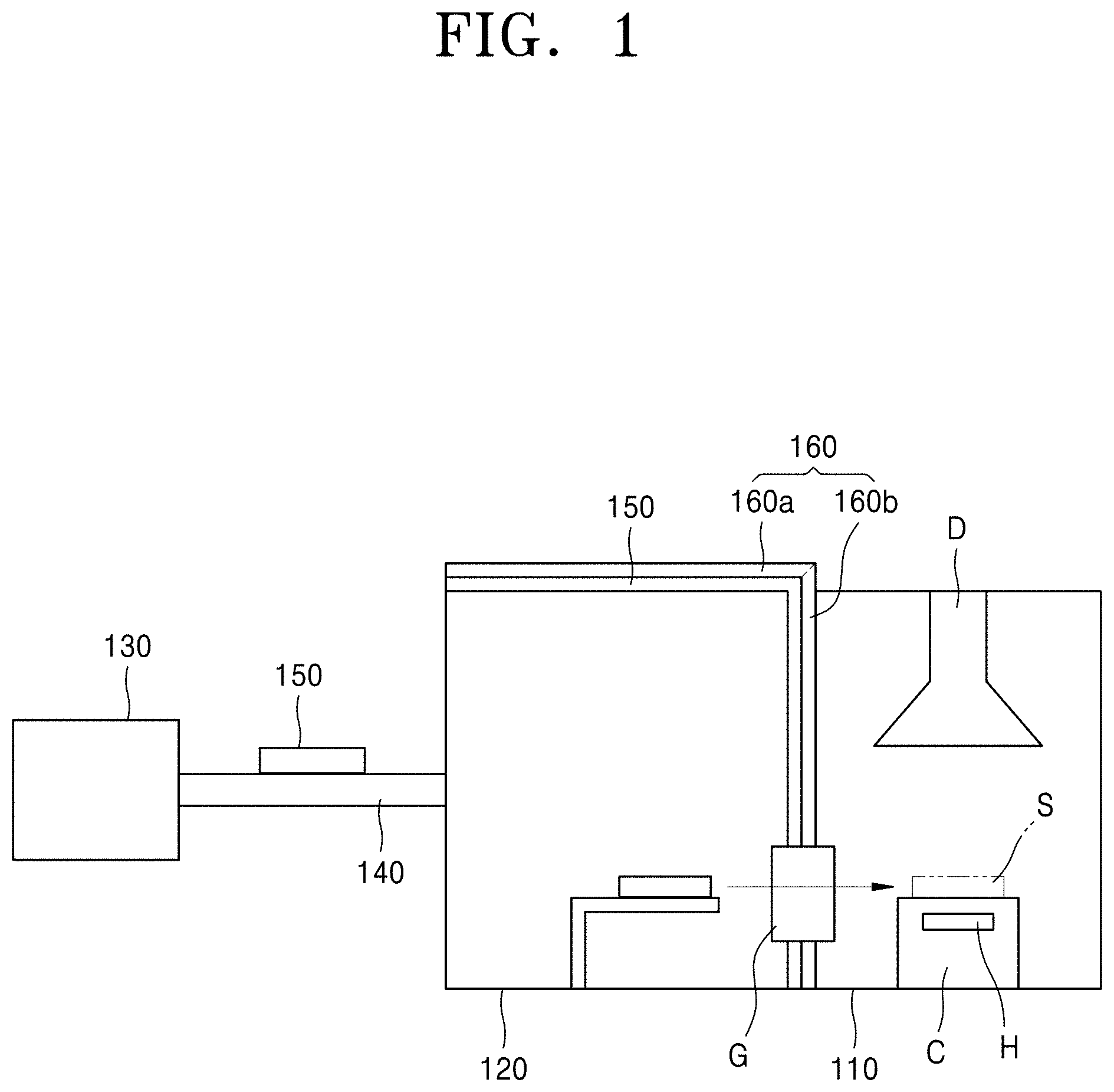
[0037] FIG. 1 is a diagram of a substrate processing system according to embodiments of the present disclosure. The substrate processing system may include at least one substrate processing apparatus, and in one example, the substrate processing system may denote one substrate processing apparatus. An example of the substrate processing apparatus described in the present specification may include a deposition apparatus of a semiconductor or display substrate, but is not limited thereto. The substrate processing apparatus may be any apparatus required to perform deposition of a material for thin-film formation, or may denote an apparatus to which a raw material for etching or polishing of a material is uniformly supplied.
[0038] Referring to FIG. 1, the substrate processing system may include a first chamber 110, a second chamber 120, a gas supplier 130, a gas supply line 140, a temperature control unit 150, and a protective cover 160.
[0039] The first chamber 110 may provide a space where at least one substrate S is accommodated. For example, the substrate S may be accommodated in the first chamber 110, and the substrate S accommodated in the first chamber 110 may be reacted (for example, a chemical reaction for deposition). For example, the first chamber 110 may be a reaction chamber. Although FIG. 1 illustrates that the first chamber 110 processes one substrate S, the first chamber 110 may be configured to process a plurality of substrates S.
[0040] For example, when the first chamber 110 is a reaction chamber for performing a deposition process, the first chamber 110 may include a chamber wall where a gate G is arranged, a substrate support C, a heater H, and a gas supply unit D. The substrate S may be led into the chamber wall through the gate G. The heater H may be provided adjacent to the substrate support C to adjust a temperature (for example, heat) of the substrate S and a reaction space. The gas supply unit D may be configured to supply a source gas and/or a reaction gas towards the substrate S located on the substrate support C.
[0041] The second chamber 120 may be configured to transfer the substrate S to the first chamber 110. For example, the substrate S is located on a substrate transfer unit included in the second chamber 120, and the substrate S may be transferred from the second chamber 120 to the first chamber 110 by the substrate transfer unit. The substrate S is processed in the first chamber 110, and then may be transferred from the first chamber 110 to the second chamber 120 by the substrate transfer unit again. The gate G may be opened or closed for transfer of the substrate S, and at this time, heat energy of the first chamber 110 may be transmitted to the second chamber 120. Such heat transmission may cause decrease of temperature of the reaction space of the first chamber 110. In this regard, the substrate processing system may further include the gas supplier 130, the gas supply line 140, and the temperature control unit 150 so as to prevent the temperature decrease and an additional heating time to compensate for the temperature reduction.
[0042] The gas supplier 130 may be configured to supply a gas (for example, nitrogen) to the second chamber 120. The gas supplied by the gas supplier 130 may be transmitted to the second chamber 120 through the gas supply line 140, and accordingly, the second chamber 120 may be filled with the gas. Pressure of the gas filled in the second chamber 120 as such may be equal to or higher than pressure of a gas of the first chamber 110.
[0043] For example, the pressure of the gas of the second chamber 120 may be equal to the pressure of the gas of the first chamber 110, and accordingly, when the first chamber 110 and the second chamber 120 communicate with each other (for example, when the gate G is opened), the gas in the first chamber 110 may be prevented from moving to the second chamber 120. As another example, the pressure of the gas of the second chamber 120 may be higher than the pressure of the gas of the first chamber 110, and accordingly, when the first and second chambers 110 and 120 communicate with each other for a substrate exchange between chambers, the gas of the second chamber 120 may be partially introduced to the first chamber 110.
[0044] The temperature control unit 150 may be configured to change a temperature of the gas in the second chamber 120. For example, the temperature control unit 150 may include a heater configured to increase a temperature of the gas in the second chamber 120. As another example, the temperature control unit 150 may include a cooler configured to lower the temperature of the gas in the second chamber 120.
[0045] The temperature control unit 150 may be provided at at least one of the gas supplier 130, the gas supply line 140, and the second chamber 120, and accordingly, the temperature of the gas supplied to the second chamber 120 may be changed. Meanwhile, when the pressure of the gas of the second chamber 120 is higher than the pressure of the gas of the first chamber 110, and the first and second chamber 110 and 120 communicate with each other, a part of the gas of the second chamber 120 may be introduced to the first chamber 110.
[0046] According to another embodiment, the substrate processing system may further include a third chamber providing a space where at least one substrate is accommodated. The third chamber may be a reaction chamber or a load lock chamber. According to some embodiments, the temperature control unit 150 may be configured to change the temperature of the gas in the second chamber 120 to correspond to a temperature condition of the third chamber when a substrate moves from the first chamber 110 to the third chamber.
[0047] For example, when the third chamber requires a temperature condition of a relatively high temperature (for example, 500.degree. C. or higher), the temperature control unit 150 may heat the gas in the third chamber to match the temperature condition. As another example, when the third chamber requires a temperature condition of a relatively low temperature (for example, room temperature), the temperature control unit 150 may cool the gas in the third chamber to match the temperature condition.
[0048] Protective covers 160a and 160b may block energy (for example, heat energy) discharged from the temperature control unit 150. The protective cover 160 may include a material having low heat conductivity. According to another embodiment, the protective cover 160a may be provided on the temperature control unit 150 such that an operator is not affected by the temperature control unit 150. According to another embodiment, the protective cover 160b may be provided between the first chamber 110 and the second chamber 120 such that a temperature change in any one of the first and second chambers 110 and 120 does not affect the other.
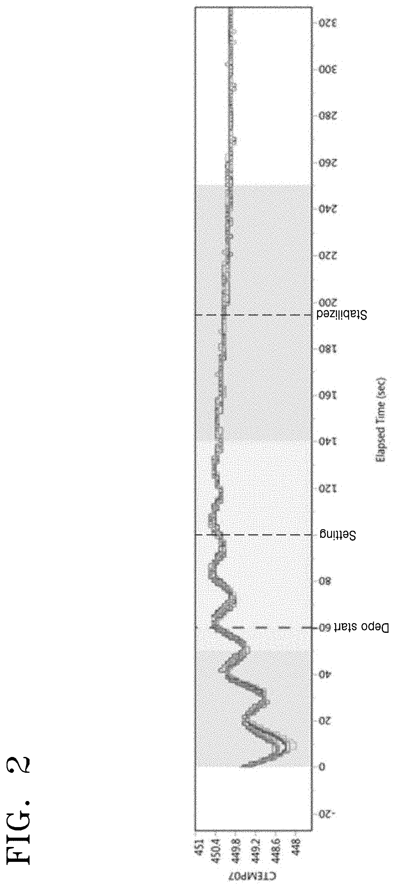
[0049] FIG. 2 shows a change in a temperature of the substrate support C (i.e., a temperature of the substrate support C by the heater H) after the substrate S is loaded onto the substrate support C. Referring to FIG. 2, at least 140 seconds are consumed for the substrate support C to reach a set temperature of 450.degree. C. and stably maintain the set temperature. However, due to productivity improvement issues or the like, a process is performed on the substrate S mostly after a preheat period of 60 seconds.
[0050] In this case, as shown in FIG. 2, there is a temperature deviation, and thus initial thin-film formation may not be smooth. In other words, when a gate between a first chamber (for example, a reaction chamber) and a second chamber (for example, a substrate transfer chamber) is opened (i.e., when chambers communicate) for loading/unloading of a substrate, heat inside a heater block and a reactor (generally, a wall of the reactor is heated) shifts to the substrate transfer chamber, and accordingly, a temperature of the heater block is not uniform and stable after the substrate is loaded.
[0051] According to one or more embodiments of the present disclosure, a gas having a temperature suitably changed through a temperature control unit exists in a second chamber. Accordingly, heat loss of a first chamber, which may occur while a substrate is exchanged between the first and second chambers, may be prevented or reduced. Consequently, stability of a process may be secured while a time required to preheat the substrate is reduced.
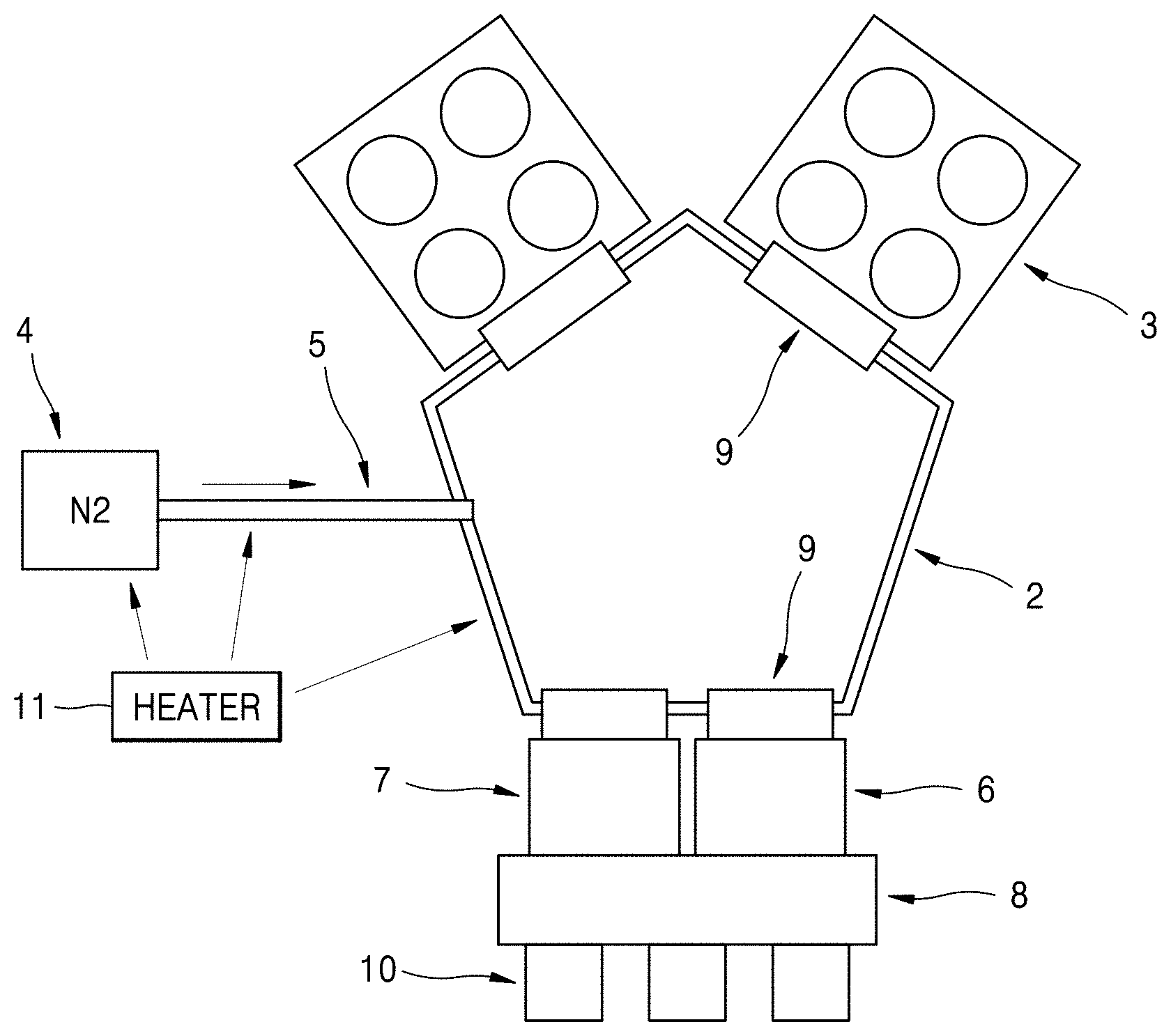
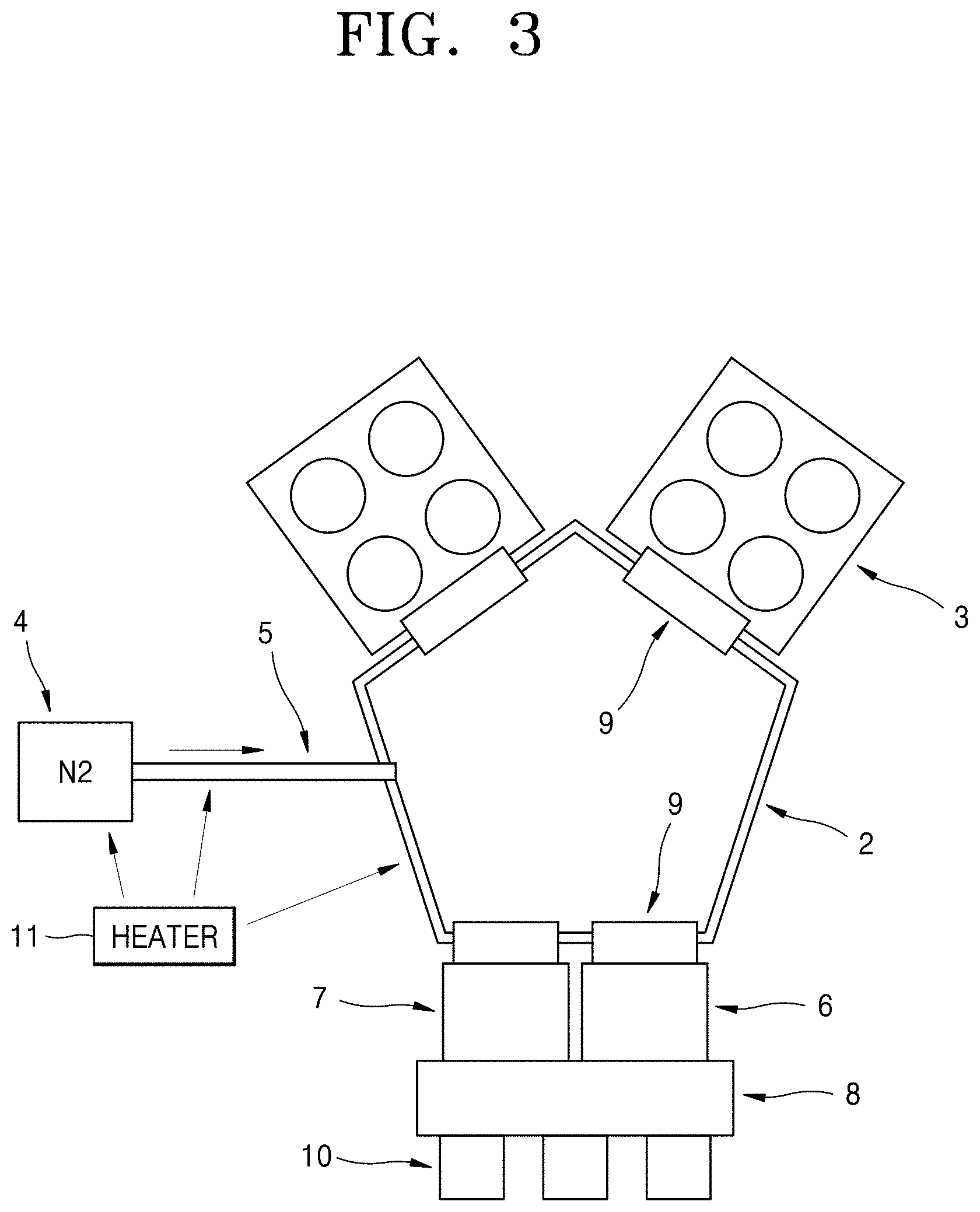
[0052] FIG. 3 is a cross-sectional view of a substrate processing system according to another embodiment of the present disclosure. The substrate processing system according to the current embodiment may be a modified example of the substrate processing system according to the previous embodiment. Hereinafter, overlapping descriptions are omitted.
[0053] Referring to FIG. 3, the substrate processing system may include load lock chambers 6 and 7, a reaction chamber 3, a substrate transfer chamber 2, a transport module 8, a gas supplier 4, a gas supply line 5, a substrate storage portion 10, and a heater 11.
[0054] The load lock chambers 6 and 7 may accommodate at least one substrate. The load lock chambers 6 and 7 temporarily store a substrate transferred from the substrate storage portion 10 to be moved to the reaction chamber 3 through the substrate transfer chamber 2 or vice versa. A vacuum pump (not shown) may be connected to the load lock chambers 6 and 7, and the vacuum pump may be controlled to adjust pressure of the load lock chambers 6 and 7 to be the same as that of the substrate transfer chamber 2. The load lock chambers 6 and 7 may align the substrate before the substrate is transferred to the reaction chamber 3. Selectively or additionally, the load lock chambers 6 and 7 may cool the substrate that has been processed in the reaction chamber 3.
[0055] The reaction chamber 3 may accommodate at least one substrate, and a process may be performed on the substrate in the reaction chamber 3. The reaction chamber 3 provides at least one reaction space, and FIG. 3 illustrates the reaction chamber 3 providing four reaction spaces, as an example. In other words, a plurality of (for example, four) substrates may be loaded and simultaneously processed. For example, substrate processing may include at least one of depositing, etching, and cleaning.
[0056] Each reaction space in the reaction chamber 3 may include a heater block (for example, a substrate support where a heater is installed) where a substrate is loaded and supplying heat to the substrate, and a gas supply unit supplying a process gas to the substrate. The gas supply unit may be a showerhead, or may be a lateral gas flow apparatus. Also, a plasma unit activating a supplied gas may be added to perform a plasma process. The reaction chamber 3 may be connected to an exhaust pump (not shown), and accordingly maintain a vacuum state. In addition, as described above, the reaction chamber 3 may include a temperature control unit for controlling a temperature (for example, heating) of an internal space.
[0057] The substrate transfer chamber 2 may be configured to transfer a substrate between the load lock chambers 6 and 7 and the reaction chamber 3. In other words, the substrate transfer chamber 2 may load the substrate from the load lock chambers 6 and 7, or may collect the substrate from the reaction chamber 3 and unload the substrate to the load lock chambers 6 and 7. The substrate transfer chamber 2 may include a substrate transfer unit (not shown), such as a robot arm. Through the substrate transfer unit, the substrate may be transferred to the reaction chamber 3 from the load lock chambers 6 and 7 and the substrate that has been processed in the reaction chamber 3 may be transferred to the load lock chambers 6 and 7.
[0058] A gate 9 may be provided between the substrate transfer chamber 2 and the reaction chamber 3, and between the substrate transfer chamber 2 and the load lock chambers 6 and 7. The gate 9 may be closed except when a substrate is loaded or unloaded. Accordingly, the substrate transfer chamber 2 and the reaction chamber 3, and the substrate transfer chamber 2 and the load lock chambers 6 and 7 may be isolated from each other except when the substrate is loaded or unloaded. The substrate transfer chamber 2 may be connected to the exhaust pump such that a vacuum state of the substrate transfer chamber 2 is maintained.
[0059] The transport module 8 is a device that transfers a substrate, such as a semiconductor wafer, from the substrate storage portion 10, such as a front opening unified pod (FOUP), to the load lock chambers 6 and 7, and may be an equipment front end module (EFEM). The transport module 8 may be located between the substrate storage portion 10 where at least one substrate is stored, and the load lock chambers 6 and 7. The transport module 8 may include the substrate transfer unit, and a substrate may be exchanged between the substrate storage portion 10 and the load lock chambers 6 and 7 through the substrate transfer unit.
[0060] The gas supplier 4 may be configured to supply a gas to the substrate transfer chamber 2. For example, the gas supplier 4 may supply a gas (for example, a nitrogen and/or inert gas) to the substrate transfer chamber 2 through the gas supply line 5. In this regard, the gas supply line 5 may connect the gas supplier 4 and the substrate transfer chamber 2.
[0061] According to another embodiment, a flow controller (not shown) and a valve (not shown) may be installed in the gas supply line 5. The flow controller and the valve may uniformly maintain the amount of gas supplied (for example, a nitrogen gas) filled in the substrate transfer chamber 2.
[0062] A gas (for example, a nitrogen gas) is filled inside the substrate transfer chamber 2. The filled gas may prevent a gas in the reaction chamber 3 from moving to the substrate transfer chamber 2 when the gate 9 between the reaction chamber 3 and the substrate transfer chamber 2 is opened.
[0063] A source gas, a reaction gas, or an etching gas supplied over a substrate remains in the reaction chamber 3, and thus when the substrate moves to the substrate transfer chamber 2, the above gas also moves to the substrate transfer chamber 2, thereby corroding or damaging portions of the substrate transfer chamber 2. Accordingly, a gas, such as a nitrogen and/or inert gas, may be filled in the substrate transfer chamber 2 to prevent corrosion or damage from the corrosive gas.
[0064] In addition, a substrate processing apparatus and a substrate processing system including the substrate processing apparatus, according to one or more embodiments of the present disclosure, may include the temperature control unit 150 for adjusting a temperature of the gas, in particular, the heater 11. The heater 11 may be provided at at least one of the substrate transfer chamber 2 and the gas supply line 5. Accordingly, a temperature of a gas may be increased by the heater 11 while the gas moves from the gas supply line 5 to the substrate transfer chamber 2.
[0065] The heater 11 may heat a gas before a substrate is introduced to the reaction chamber 3 and before the substrate is discharged from the reaction chamber 3. Accordingly, when the reaction chamber 3 and the substrate transfer chamber 2 communicate, a change in a temperature of the reaction space in the reaction chamber 3 may be minimized even when at least some of the gas heated by the heater 11 is introduced from the substrate transfer chamber 2 to the reaction chamber 3. Accordingly, the problem of the loss of a substrate temperature stabilization time due to an exchange of a substrate, and the loss of productivity caused thereby may be solved.
[0066] FIG. 4 is a cross-sectional view of a substrate processing system according to another embodiment of the present disclosure. The substrate processing system according to the current embodiment may be a modified example of the substrate processing system according to the previous embodiment. Hereinafter, overlapping descriptions are omitted.
[0067] Referring to FIG. 4, the heater 11 is provided around the substrate transfer chamber 2 and the gas supply line 5. For example, the heater 11 may be provided at the substrate transfer chamber 2, and accordingly, a gas in the substrate transfer chamber 2 may be heated. According to another embodiment, the heater 11 may be provided at the gas supply line 5, and accordingly, a gas passing through the gas supply line 5 may be heated.
[0068] Accordingly, a gas (for example, a nitrogen gas) supplied from the gas supplier 4 supplying a gas may be heated to a certain temperature while passing through the heated gas supply line 5, and then may be continuously heated by the heater 11 even while being filled in the substrate transfer chamber 2. In addition, a state in which the substrate transfer chamber 2 and a gas (for example, a nitrogen gas) filled therein are being heated may be maintained.
[0069] When the reaction chamber 3 and the substrate transfer chamber 2 communicate with each other, pressure of a gas of the substrate transfer chamber 2 may be equal to or higher than pressure of a gas of the reaction chamber 3. Accordingly, the gas (i.e., a remaining gas) of the reaction chamber 3 may not be introduced to the substrate transfer chamber 2 even when the gate 9, i.e., a valve, between the reaction chamber 3 and the substrate transfer chamber 2 is opened for loading or unloading of a substrate, and loss of heat of the heater block of the reactor provided in the reaction chamber 3 to the substrate transfer chamber 2 may be reduced.
[0070] According to another embodiment, at least some of a gas heated by the heater 11 may be introduced from the substrate transfer chamber 2 to the reaction chamber 3. Accordingly, heat energy of the heated gas may be transmitted from the substrate transfer chamber 2 to the reaction chamber 3. According to another embodiment, a temperature of the gas heated by the heater 11 may be equal to or higher than an internal temperature of the reaction chamber 3. For example, heat energy may be transmitted by a temperature difference even when a gas is not exchanged between the reaction chamber 3 and the substrate transfer chamber 2.
[0071] According to an embodiment, when a substrate is introduced from the substrate transfer chamber 2 to the reaction chamber, 3, a temperature of the gas heated by the heater 11 may be set to be higher than the internal temperature of the reaction chamber 3. A temperature of the substrate before being processed is relatively low. Accordingly, the temperature of the gas heated by the heater 11 may be set to be higher than the internal temperature of the reaction chamber 3 such that a preheat time with respect to the substrate having the relatively low temperature is reduced, and heat energy (or the gas having heat energy) may be transmitted to the reaction chamber 3 from the substrate transfer chamber 2.
[0072] According to another embodiment, when a substrate is transferred from the reaction chamber 3 to the substrate transfer chamber 2, the temperature of the gas heated by the heater 11 may be set to be equal to or lower than the internal temperature of the reaction chamber 3. During the movement of the substrate, a preheat time in the reaction chamber 3 described above is not required, and the substrate may be moved to the load lock chambers 6 and 7 to be cooled. Accordingly, the temperature of the gas heated by the heater 11 may be set to be lower than the internal temperature of the reaction chamber 3. However, according to another embodiment, the substrate transfer chamber 2 may move the substrate to another reaction chamber (hereinafter, referred to as a second reaction chamber) 12 instead of the load lock chambers 6 and 7, and in this case, the temperature of the gas heated by the heater 11 may be set to be equal to or higher than an internal temperature of the second reaction chamber 12, i.e., a temperature of a reaction space during a reaction.
[0073] According to another embodiment, the heater 11 may be configured to heat a gas before a substrate is introduced to the reaction chamber 3. Also, the heater 11 may be configured to heat the gas before the substrate is discharged from the reaction chamber 3. As such, by suitably adjusting the temperature of the gas in the substrate transfer chamber 2 before the gate G between the reaction chamber 3 and the substrate transfer chamber 2 is opened, a process may be stably performed and productivity may be increased.
[0074] In FIG. 4, the gas supply line 5 and the substrate transfer chamber 2 are heated by a single heater 11, but the gas supply line 5 and the substrate transfer chamber 2 may be independently heated. For example, the heater 11 may include a first heater provided at the gas supply line 5 and a second heater provided at the substrate transfer chamber 2, and the first and second heaters may be independently heated. According to another embodiment, a first heating temperature of the first heater may be equal to or higher than, or equal to or lower than a second heating temperature of the second heater. A gas may be quickly and efficiently heated through such independent heating of heaters and a temperature gradient configuration.
[0075] Also, in FIG. 4, only a side surface of the substrate transfer chamber 2 is heated, but top and bottom surfaces (not shown) of the substrate transfer chamber 2 may be heated by the heater 11. Also, according to another embodiment, a protective cover having low thermal conductivity may be provided on the heater 11 for safety of an operator. The protective cover may block heat generated by the heater 11 from being externally emitted.
[0076] The protective cover may be provided not only for the safety of operator, but also to prevent thermal conduction between chambers. For example, the protective cover having low thermal conductivity may be provided between the reaction chamber 3 and the substrate transfer chamber 2 and/or between the load lock chambers 6 and 7 and the substrate transfer chamber 2 so as to prevent thermal conduction between the reaction chamber 3 and the substrate transfer chamber 2 and thermal conduction between the load lock chambers 6 and 7 and the substrate transfer chamber 2.
[0077] According to another embodiment, in order to reduce a thermal shock from the heated gas (for example, a nitrogen and/or inert gas) and/or a thermal shock from the heated substrate transfer chamber 2, a coolant or a cooling member corresponding to the coolant may be supplied to the substrate transfer unit in the substrate transfer chamber 2. Examples of the cooling member for preventing the thermal shock may include an insulation member passively preventing a temperature increase and a cooling unit actively lowering a temperature, but are not limited thereto.
[0078] According to an embodiment, by heating the substrate transfer chamber 2 and a filling gas supplied thereto, heat loss from the reaction chamber 3 to the substrate transfer chamber 2 may be reduced while loading or unloading a substrate, and a preheat time of the substrate may be reduced, and thus the number of processed substrate per hour may increase.
[0079] FIG. 5 is a flowchart of a substrate processing method according to an embodiment of the present disclosure. The substrate processing method according to the current embodiment may be a modified example using the substrate processing system according to the previous embodiment. Hereinafter, overlapping descriptions are omitted.
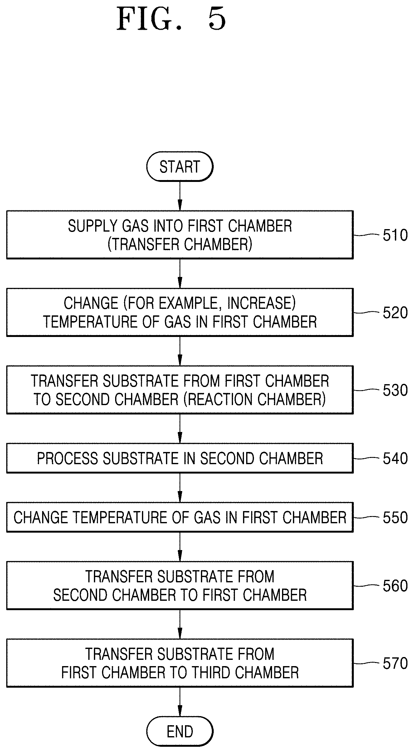
[0080] Referring to FIG. 5, in operation 510, a gas is supplied into a first chamber (for example, a transfer chamber). In operation 520, a temperature of the gas in the first chamber is changed (for example, increased). The supplying of the gas and the changing of the temperature of the gas may take place simultaneously. For example, a gas from a gas supplier may be supplied to the first chamber through a gas supply line, and a temperature of the gas may change while the gas is supplied to the first chamber, by a temperature control unit provided at the gas supply line.
[0081] In operation 530, the substrate is transferred from the first chamber to the second chamber (for example, a reaction chamber). The temperature of the substrate may change according to a change in the temperature of the gas supplied to the first chamber, and accordingly, the substrate having the changed temperature may be transferred to the second chamber. According to another embodiment, while the temperature of the gas in the first chamber changes, a temperature of a substrate transfer unit in the first chamber may also change. An additional temperature control unit may be provided in the substrate transfer unit so as to prevent an effect (for example, a thermal shock) of the temperature change on the substrate transfer unit.
[0082] After the substrate is transferred to the second chamber, the substrate is processed in the second chamber in operation 540. As described above, a preheat time of the substrate in the second chamber is an important factor determining productivity. According to one or more embodiments of the present disclosure, heat loss that may occur while a substrate is loaded may be reduced, and thus a preheat time at an initial stage of processing the substrate may be reduced.
[0083] Such a preheat for reducing the heat loss may take place before the substrate is introduced to the second chamber, and also before the substrate is discharged from the second chamber, moved back to the first chamber, and then moved to the third chamber. For example, after the substrate is processed in the second chamber, a temperature of a gas in the first chamber is set to change in operation 550. Here, a set temperature of the gas may be determined considering a reaction temperature in the third chamber. For example, operations 540 and 550 may be simultaneously performed. In other words, while the substrate is processed in the second chamber, the temperature of the gas in the first chamber may change.
[0084] The substrate is transferred from the second chamber back to the first chamber in operation 560, and then the substrate is transferred from the first chamber to the third chamber in operation 570. Accordingly, the substrate may be additionally processed in the third chamber. At this time, since the temperature of the gas in the first chamber is heated considering the reaction temperature of the third chamber, heat loss that may occur while transferring the substrate from the first chamber to the third chamber may be reduced. Accordingly, a preheat time at an initial stage for processing the substrate with respect to various chambers (for example, a plurality of reaction chambers) may be reduced. For example, when a substrate is processed stepwise by being transferred to a plurality of reactors starting from a first chamber, a temperature of a gas filled in the first chamber may be adjusted suitably to a next reactor while the substrate is being processed in a previous reactor to reduce a preheat time in each reactor, thereby improving productivity.
[0085] It should be understood that embodiments described herein should be considered in a descriptive sense only and not for purposes of limitation. Descriptions of features or aspects within each embodiment should typically be considered as available for other similar features or aspects in other embodiments.
[0086] While one or more embodiments have been described with reference to the figures, it will be understood by those of ordinary skill in the art that various changes in form and details may be made therein without departing from the spirit and scope of the disclosure as defined by the following claims.
* * * * *
D00000
D00001
D00002
D00003
D00004
D00005
XML
uspto.report is an independent third-party trademark research tool that is not affiliated, endorsed, or sponsored by the United States Patent and Trademark Office (USPTO) or any other governmental organization. The information provided by uspto.report is based on publicly available data at the time of writing and is intended for informational purposes only.
While we strive to provide accurate and up-to-date information, we do not guarantee the accuracy, completeness, reliability, or suitability of the information displayed on this site. The use of this site is at your own risk. Any reliance you place on such information is therefore strictly at your own risk.
All official trademark data, including owner information, should be verified by visiting the official USPTO website at www.uspto.gov. This site is not intended to replace professional legal advice and should not be used as a substitute for consulting with a legal professional who is knowledgeable about trademark law.