Automatic Fault Diagnosable Integrated Sheet Body Punching And Grinding Assembly
LI; CHUAN
U.S. patent application number 16/417547 was filed with the patent office on 2019-12-26 for automatic fault diagnosable integrated sheet body punching and grinding assembly. The applicant listed for this patent is DONGGUAN UNIVERSITY OF TECHNOLOGY. Invention is credited to CHUAN LI.
| Application Number | 20190389024 16/417547 |
| Document ID | / |
| Family ID | 64026362 |
| Filed Date | 2019-12-26 |


| United States Patent Application | 20190389024 |
| Kind Code | A1 |
| LI; CHUAN | December 26, 2019 |
AUTOMATIC FAULT DIAGNOSABLE INTEGRATED SHEET BODY PUNCHING AND GRINDING ASSEMBLY
Abstract
The present invention relates to an automatic fault diagnosable integrated sheet body punching and grinding assembly, including a frame and a conveying slot seat, a processing frame is provided on the conveying slot seat, the processing frame is sequentially provided with a punching device and a grinding device; the frame is provided with a feeding motor and a feeding screw cooperating with each other, the feeding screw is sleeved with a movable feeding block, and the movable feeding block is fixedly connected with a movable feeding seat, the movable feeding seat is provided with a feeding lift cylinder, the feeding lift cylinder is provided with a feeding lift block; the feeding lift block is evenly disposed with feeding blocks that can pass through the feeding slot, and the distance between the processing portion of the punching device and the grinding device is the same as that between the adjacent two feeding blocks. In the present invention, the conveying slot seat cooperates with the fixed distance feeding part to realize the fixed distance feeding of the sheet bodies, the punching device and the grinding device are provided sequentially on the conveying slot seat, which enables continuous automatic punching and grinding of sheet bodies, thereby greatly improves the efficiency of punching and grinding of the sheet bodies.
| Inventors: | LI; CHUAN; (DONGGUAN, CN) | ||||||||||
| Applicant: |
|
||||||||||
|---|---|---|---|---|---|---|---|---|---|---|---|
| Family ID: | 64026362 | ||||||||||
| Appl. No.: | 16/417547 | ||||||||||
| Filed: | May 20, 2019 |
| Current U.S. Class: | 1/1 |
| Current CPC Class: | Y10T 83/6476 20150401; Y10T 83/9418 20150401; Y10T 29/5136 20150115; B23P 23/02 20130101; B23Q 15/225 20130101; Y10T 29/517 20150115; Y10T 29/5146 20150115; B24B 51/00 20130101; B23P 23/04 20130101; B21D 28/04 20130101; B26F 1/02 20130101; B23Q 17/2419 20130101; B23Q 17/2471 20130101; B23Q 17/22 20130101 |
| International Class: | B23Q 17/24 20060101 B23Q017/24; B26F 1/02 20060101 B26F001/02; B24B 51/00 20060101 B24B051/00; B23Q 17/22 20060101 B23Q017/22; B23Q 7/03 20060101 B23Q007/03; B23Q 15/22 20060101 B23Q015/22 |
Foreign Application Data
| Date | Code | Application Number |
|---|---|---|
| Jun 25, 2018 | CN | CN2018106594162 |
Claims
1. An automatic fault diagnosable integrated sheet body punching and grinding assembly, including a frame (1) and a conveying trough seat (2) disposed on the frame (1); a feed trough (3) is disposed in the middle portion of the conveying trough seat (2), and a processing frame (12) is disposed on the conveying trough seat (2); the processing frame (12) is sequentially provided with a punching device (13) and a grinding device (14) matching with the sheet body (4) in the conveying trough seat (2), the frame (1) is disposed with a feed motor (5) and a feed screw (6) cooperating with each other, the feed screw (6) is sleeved with movable feed blocks (7), the movable feed block (7) is connected with a movable feed seat (8), the movable feed seat (8) is provided with a feed lift cylinder (9), the feed lift cylinder (9) is disposed with a feed lift block (10); several feed blocks (11) which can travel along the feed trough (3) are uniformly provided on the feed lift block (10), and the distance between processing portions of the punching device (13) and the grinding device (14) is the same as that between the adjacent two feeding blocks (11).
2. The automatic fault diagnosable integrated sheet body punching and grinding assembly of claim 1, wherein the feed block (11) is an L-shaped block, and the length of horizontal portion thereof is consistent with the length of the sheet body; the feed blocks (11) located at the punching station and the grinding station are provided with a discharging opening (26) matching with the punching and grinding portion of the sheet body; the feed lift block (10) is provided with a collect port (27) which is connected with the discharging opening (26); on the movable feeding seat (8) is provided a collection assembly (15) cooperating with the collect port (27).
3. The automatic fault diagnosable integrated sheet body punching and grinding assembly of claim 1, wherein a processing lift cylinder (21) is provided below the processing frame (12), and a processing lift seat (22) is connected below the processing lift cylinder (21), the length of the processing lift seat (22) is consistent with the distance between the adjacent two feeding blocks (11); a fitting opening is provided directly above the vertical portion of the feed block (11), the punching device (13) and the grinding device (14) are all disposed below the processing lift seat (22); the grinding device (14) includes a grinding motor (23) disposed under the processing lift seat (22), and a grinding head (24) is disposed under the grinding motor (23); the part of the processing lift seat (22) corresponding to both sides of the grinding motor (23) is connected to a grinding press block (31) corresponding with the product on the feed block (11) through processing buffer springs (30), the grinding head (24) cooperates with the grinding press block (31) by plugging and fitting.
4. The automatic fault diagnosable integrated sheet body punching and grinding assembly of claim 3, wherein the lower portion of the grinding head (24) is tapered, the beam receiver (25) is embedded in the middle of the bottom surface of the grinding head (24), a beam emitter (29) is disposed within the feeding lift block (10), the beam emitter mounting plate (28) of the beam emitter (29) is fixed in the feed lift block (10) by bolts, the upper portion of the beam emitter (29) is flush with the lower portion of the collection port (27) connected to the discharging opening (26) of the grinding station, and the beam emitter (29) can emit a vertical beam that coincides with the axis of the discharging opening (36).
5. The automatic fault diagnosable integrated sheet body punching and grinding assembly of claim 3, wherein the lower portion of the grinding press block (31) is embedded with a first contact sensor (32), the processing lift seat (22) is provided with an inverted slot shaped feeding height detection block (33) at the portion of the fitting opening, two acoustic wave range finders (34) cooperating with the upper surface of vertical part of the feeding block (11) are provided under the feeding height detection slot (33).
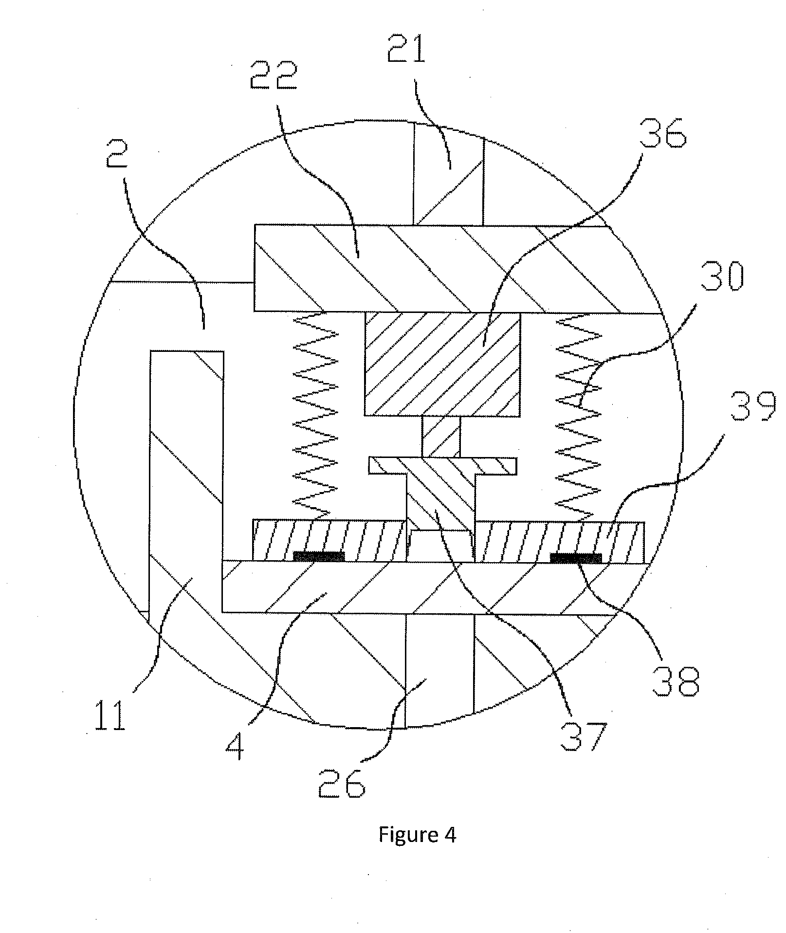
6. The automatic fault diagnosable integrated sheet body punching and grinding assembly of claim 5, wherein the punching device (13) includes a punching head (37) disposed under the processing lift seat (22), the part of processing lift seat (22) to the outside the punching head (37) is connected with a punching press block (39) cooperating with the product on the feeding block (11) by processing buffer springs (30), the punching press block (39) cooperates with the punching head (37) by plugging and fitting, and a second contact sensor (38) is embedded in the lower portion of the punching block (39).
7. The automatic fault diagnosable integrated sheet body punching and grinding assembly of claim 6, wherein the lower portion of the processing lift seat (22) is provided with a punching rotary motor (36), the punching head (37) is provided under the punching rotary motor (36), the lower portion of the punching head (37) is an rotary cutter, and the upper end thereof is a baffle block larger than the punching diameter.
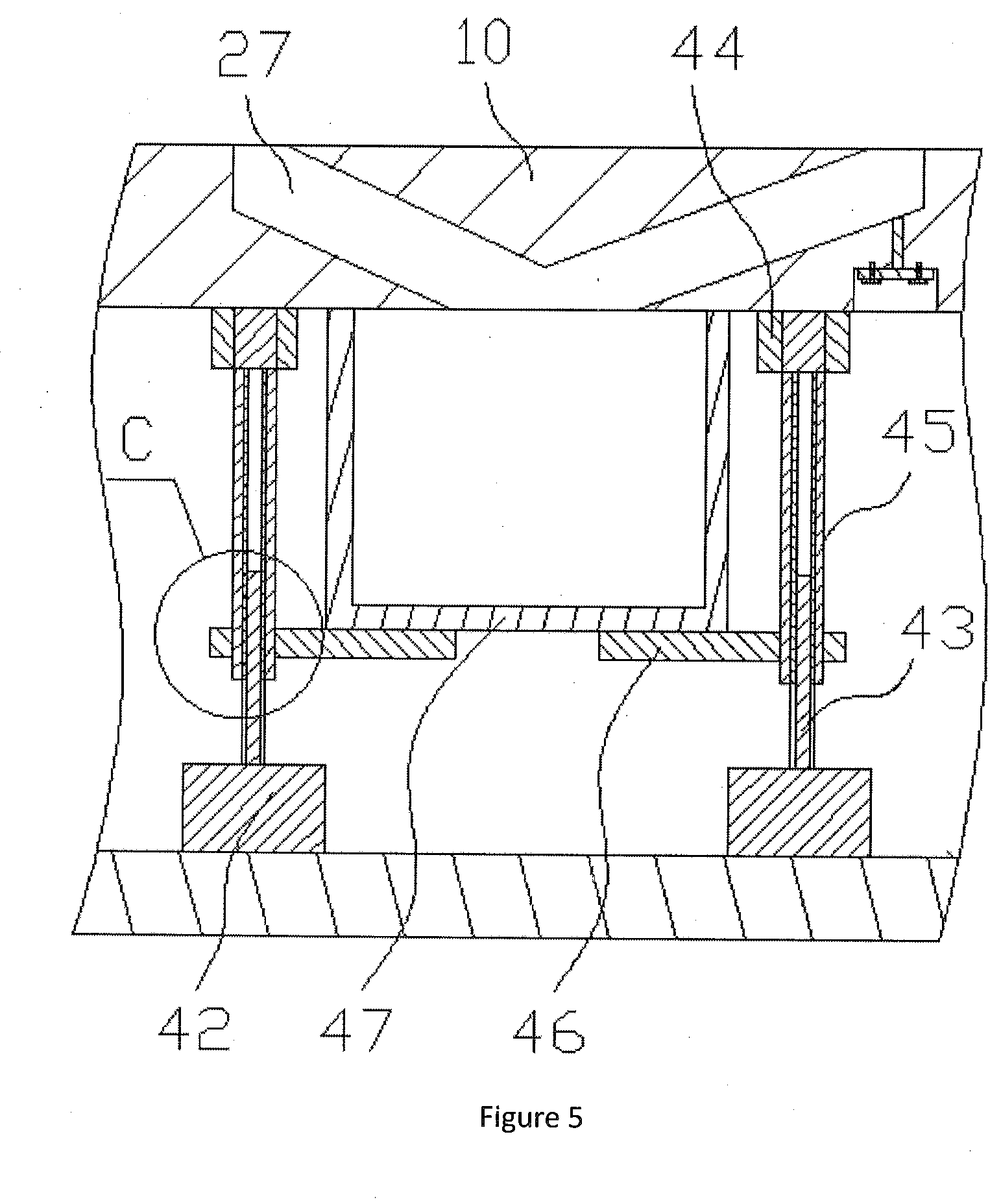
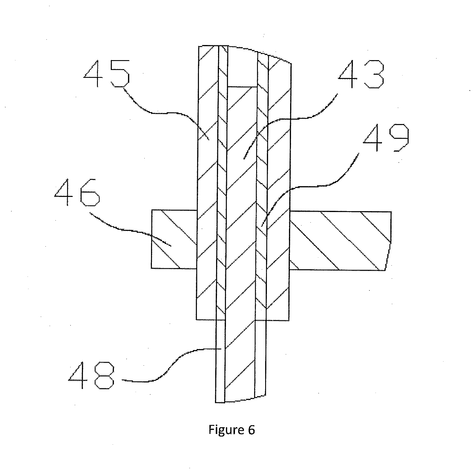
8. The automatic fault diagnosable integrated sheet body punching and grinding assembly of claim 2, wherein the collect device (15) includes 2 collect assembly motors (42) disposed on the feed lift seat (8), and the 2 collect assembly motors (42) are provided on both sides of the collect port (27), and upper portion of the collecting assembly motors (42) are connected with a vertically oriented collecting assembly rotary shafts (43); the outside of the collecting assembly rotary shafts (43) are sleeved with a collect assembly rotating sleeves (45), the collect assembly rotating sleeves (45) are disposed inside the rotating sleeve bearing housings (44), which are provided below the feed lift block (10); the outer sides of the collecting assembly rotary shafts (43) are provided with a vertical oriented rotating shaft mating sockets (48); the collect assembly rotating sleeves (45) are provided with a rotating shaft mating plugs (49) matching the rotating shaft mating socket (48), the lower portion of the collect assembly rotating sleeves (45) are fixedly sleeved with collect support rotating blocks (46), and collect box (47) is disposed on the two support collection blocks (46).
Description
FIELD OF THE INVENTION
[0001] The present invention relates to the field of integrity detection of the processing equipment, and more specifically to an automatic fault diagnosable integrated sheet body punching and grinding assembly.
BACKGROUND OF THE INVENTION
[0002] As a commonly used processing material, the sheet body is widely used, especially in the use of gaskets and connecting sheets. In order to achieve a better matching installation structure, gaskets are sometimes punched.
[0003] Most sheet bodies need to be grinded after being punched to grind the punched holes smoothly. Existing devices usually separate the process of punching and grinding, in this case, two devices are required for processing. Moreover, as it is necessary to reclaim, position and locate material for each device, production efficiency is low, and continuous processing cannot be achieved.
OVERALL OBJECTIVE OF THE INVENTION
[0004] The overall objective of the present invention is to provide a automatic fault diagnosable integrated sheet body punching and grinding assembly, the conveying slot seat is fitted with the fixed distance feeding part to realize the fixed distance feeding of the sheet body, the punching device and the grinding device are disposed in sequence with the top of the conveying slot seat, which enables continuous automatic punching and grinding of the sheet body, thereby greatly improving the efficiency of punching and grinding of the sheet body.
SUMMARY OF THE INVENTION
[0005] In order to achieve the above objective, the technical solution adopted by the present invention are: an automatic fault diagnosable integrated sheet body punching and grinding assembly, including a frame and a conveying trough seat disposed on the frame; a feed trough is disposed in the middle portion of the conveying trough seat, and a processing frame is disposed on the conveying trough seat; the processing frame is sequentially provided with a punching device and a grinding device matching with the sheet body in the conveying trough seat, the frame is disposed with a feed motor and a feed screw cooperating with each other, the feed screw is sleeved with movable feed blocks, the movable feed block is connected with a movable feed seat, the movable feed seat is provided with a feed lift cylinder, the feed lift cylinder is disposed with a feed lift block; several feed blocks which can penetrate the feed trough are uniformly provided on the feed lift block, and the distance between processing portions of the punching device and the grinding device is the same as that between the adjacent two feeding blocks. Preferably, the feed block is an L-shaped block, and the length of horizontal portion thereof is consistent with the length of the sheet body. The feed blocks located at the punching station and the grinding station are provided with a discharging opening matching with the punching and grinding portion of the sheet body. The feed lift block is provided with a collect port which is connected with the discharging opening; on the movable feeding seat is provided a collection assembly cooperating with the collect port.
[0006] Preferably, a processing lift cylinder is provided below the processing frame, and a processing lift seat is connected below the processing lift cylinder, the length of the processing lift seat is consistent with the distance between the adjacent two feeding blocks; a fitting opening is provided directly above the vertical portion of the feed block, the punching device and the grinding device are all disposed below the processing lift seat; the grinding device includes a grinding motor disposed under the processing lift seat, and a grinding head is disposed under the grinding motor; the part of the processing lift seat corresponding to both sides of the grinding motor is connected to a grinding press block corresponding with the product on the feed block through processing buffer springs, the grinding head cooperates with the grinding press block by plugging and fitting.
[0007] Preferably, the lower portion of the grinding head is tapered, the beam receiver is embedded in the middle of the bottom surface of the grinding head, a beam emitter is disposed within the feeding lift block, the beam emitter mounting plate of the beam emitter is fixed in the feed lift block by bolts, the upper portion of the beam emitter is flush with the lower portion of the collection port connected to the discharging opening of the grinding station. And the beam emitter can emit a vertical beam that coincides with the axis of the discharging opening.
[0008] Preferably, the lower portion of the grinding press block is embedded with a first contact sensor, the processing lift seat is provided with an inverted slot shaped feeding height detection block at the portion of the fitting opening, two acoustic wave range finders cooperating with the upper surface of vertical part of the feeding block are provided under the feeding height detection slot.
[0009] Preferably, the punching device includes a punching head disposed under the processing lift seat, the part of processing lift seat to the outside the punching head is connected with a punching press block cooperating with the product on the feeding block by processing buffer springs, the punching press block cooperates with the punching head by plugging and fitting, and a second contact sensor is embedded in the lower portion of the punching block.
[0010] Preferably, the lower portion of the processing lift seat is provided with a punching rotary motor, the punching head is provided under the punching rotary motor, and the lower portion of the punching head is an rotary cutter, and the upper end thereof is a baffle block larger than the punching diameter.
[0011] Preferably, the collect device includes collect assembly motors disposed on the feed lift seat, and the collect assembly motors are provided on both sides of the collect port, and upper portion of the collecting assembly motors are connected with a vertically oriented collecting assembly rotary shafts. The outside of the collecting assembly rotary shafts are sleeved with a collect assembly rotating sleeves, the collect assembly rotating sleeves are disposed inside the rotating sleeve bearing housings, which are provided below the feed lift block. The outer side of the collecting assembly rotary shafts are provided with a vertical oriented rotating shaft mating sockets. The collect assembly rotating sleeves are provided with a rotating shaft mating plugs matching the rotating shaft mating socket, the lower portion of the collect assembly rotating sleeves are fixedly sleeved with collect support rotating blocks, and collect box is disposed on the two support collection blocks.
BRIEF DESCRIPTION OF THE DRAWINGS
[0012] FIG. 1 is a schematic structural view of the automatic fault diagnosable integrated sheet body punching and grinding assembly;
[0013] FIG. 2 is a schematic structural view of the grinding device and the punching device;
[0014] FIG. 3 is a partial enlarged view of part A in FIG. 2;
[0015] FIG. 4 is a partial enlarged view of part B in FIG. 2;
[0016] FIG. 5 is a schematic structural view of the collecting device; and
[0017] FIG. 6 is a partial enlarged view of part C in FIG. 5.
REFERENCE NUMBER KEY
[0018] The drawings includes following integers denoting the various components: [0019] 1--frame; [0020] 2--Conveying slot seat; [0021] 3--Feeding slot; [0022] 4--Sheet body; [0023] 5--Feeding motor; [0024] 6--Feeding screw; [0025] 7--Movable feeding block; [0026] 8--Movable feeding seat; [0027] 9--Feeding lift cylinder; [0028] 10--Feeding lift block; [0029] 11--Feeding block; [0030] 12--Processing frame; [0031] 13--Punching device; [0032] 14--Grinding device; [0033] 15--Collecting device; [0034] 21--Processing Lift cylinder; [0035] 22--Processing lift seat; [0036] 23--Grinding motor; [0037] 24--Grinding head; [0038] 25--Beam receiver; [0039] 26--Discharging opening; [0040] 27--Collecting port; [0041] 28--Beam emitter mounting plate; [0042] 29--Beam emitter; [0043] 30--Processing buffer spring; [0044] 31--Grinding press block; [0045] 32--First contact sensor; [0046] 33--Feeding height detection slot; [0047] 34--Acoustic wave range finder; [0048] 36--Punching rotary motor; [0049] 37--Punching head; [0050] 38--Second contact sensor; [0051] 39--Punching press block; [0052] 42--Collecting assembly motor; [0053] 43--Collecting assembly shaft; [0054] 44--Sleeve mounting bearing seat; [0055] 45--Collecting assembly rotary sleeve; [0056] 46--Collecting support rotary block; [0057] 47--Collecting frame; [0058] 48--Rotary shaft fitting socket; [0059] 49--Rotating shaft mating plug.
DETAILED DESCRIPTION OF THE ILLUSTRATED EMBODIMENT
[0060] The present invention will be described in detail below with reference to the accompanying drawings, and the description of the present invention is only exemplary and explanatory, and should not be construed as limiting the scope of the present invention.
[0061] As shown in FIG. 1, the specific structure of the present invention comprises an automatic fault diagnosable integrated sheet body punching and grinding assembly, including a frame 1 and a conveying slot seat 2 provided on the frame 1, wherein the middle of the conveying slot seat 2 is provided with a feeding slot 3, a processing frame 12 is provided on the conveying slot seat 2, the processing frame 12 is sequentially provided with a punching device 13 and a grinding device 14 fitted with a sheet body 4 in the conveying slot seat 2; the frame 1 is provided with a feeding motor 5 and a feeding screw 6 fitting with each other, the feeding screw 6 is sleeved with a movable feeding block 7, and the movable feeding block 7 is fixedly connected with a movable feeding seat 8, the movable feeding seat 8 is provided with a feeding lift cylinder 9, the feeding lift cylinder 9 is provided with a feeding lift block 10; the feeding lift block 10 is evenly disposed with feeding blocks 11 that can pass through the feeding slot 3, and the distance between the punching device 13 and the processing portion of the grinding device 14 is the same as the distance between the adjacent two feeding blocks 11.
[0062] The reciprocating feeding of the feed motor 5 is used to matching the reciprocating lifting of the lift cylinder, which may realize the reciprocating feeding and lifting of the feeding block. Further, the sheet body on the feeding trough can be fed for a fixed distance, and sequentially passes through the punching device and the grinding device. The integrated punching and grinding of the sheet body greatly improves the overall processing efficiency of the sheet body.
[0063] As shown in FIGS. 1 and 2, the feed block 11 is an L-shaped block, and the length of horizontal portion thereof is consistent with the length of the sheet body. The feed blocks 11 located at the punching station and the grinding station are provided with a discharging opening 26 matching with the punching and grinding portion of the sheet body. The feed lift block 10 is provided with a collect port 27 which is connected with the discharging opening 26; on the movable feeding seat 8 is provided a collection assembly 15 cooperating with the collect port 27.
[0064] By developing the structure of the feed blocks, the feed block can support the sheet body, and the punching and grinding effect of the sheet body can be improved, and a discharging opening is disposed to match the collect device, and the punching and grinding reject can be collected, thereby avoids interference with the feed portion.
[0065] As shown in FIGS. 2 and 3, a processing lift cylinder 21 is provided below the processing frame 12, and a processing lift seat 22 is connected below the processing lift cylinder 21, the length of the processing lift seat 22 is consistent with the distance between the adjacent two feeding blocks 11; a fitting opening is provided directly above the vertical portion of the feed block 11, the punching device 13 and the grinding device 14 are all disposed below the processing lift seat 22; the grinding device 14 includes a grinding motor 23 disposed under the processing lift seat 22, and a grinding head 24 is disposed under the grinding motor 23; the part of the processing lift seat 22 corresponding to both sides of the grinding motor 23 is connected to a grinding press block 31 corresponding with the product on the feed block 11 through processing buffer springs 30, the grinding head 24 cooperates with the grinding press block 31 by plugging and fitting.
[0066] Both the punching device and the grinding device are provided on the processing lift seat, so that the synchronous grinding can be achieved, and forces are in a balance. Meanwhile, it is also possible to detect the feeding precision from the processing conditions of the two processing parts. By providing a compactable material pressing plate cooperating with the grinding head by plugging and fitting, during descending of the grinding head, interference with the material pressing part will not occur, which achieves good material holding effect for grinding.
[0067] As shown in FIG. 3, the lower portion of the grinding head 24 is tapered, the beam receiver 25 is embedded in the middle of the bottom surface of the grinding head 24, a beam emitter 29 is disposed within the feeding lift block 10, the beam emitter mounting plate 28 of the beam emitter 29 is fixed in the feed lift block 10 by bolts, the upper portion of the beam emitter 29 is flush with the lower portion of the collection port 27 connected to the discharging opening 26 of the grinding station. And the beam emitter 29 can emit a vertical beam that coincides with the axis of the discharging opening 36.
[0068] The beam emitter is used to emit a vertical beam passing through the discharging opening, and the receiving condition of the beam receiver can be used to determine whether the feeding is accurate. If the beam receiver receives the beam from the beam emitter, the feeding is accurate, and the sheet body is fed to the accurate grinding station. Otherwise, there is an error in feeding distance and the device needs to be shut down for maintenance.
[0069] As shown in FIGS. 2 and 3, the lower portion of the grinding press block 31 is embedded with a first contact sensor 32, the processing lift seat 22 is provided with an inverted slot shaped feeding height detection block 33 at the portion of the fitting opening, two acoustic wave range finders 34 cooperating with the upper surface of vertical part of the feeding block 11 are provided under the feeding height detection slot 33.
[0070] By developing of the first contact sensor the measurement position of the acoustic range finders can be determined, the measurement of the acoustic range finders can detect the height of the vertical part of the feeding block, thus ensure the precise lifting of the feeding block. The processing lift cylinder stops lifting when the first contact sensor generates an inductive signal. If the values measured by the two acoustic range finders are consistent with the theoretical values, the feeding height is accurate, and as long as one measured values are different from the theoretical values, there is a problem with accuracy of the feeding height. Together with signal of the beam receiver, it can be judged whether the feeding distance is not accurate or the lifting accuracy is not accurate.
[0071] As shown in FIG. 4, the punching device 13 includes a punching head 37 disposed under the processing lift seat 22, the part of processing lift seat 22 to the outside the punching head 37 is connected with a punching press block 39 cooperating with the product on the feeding block 11 by processing buffer springs 30, the punching press block 39 cooperates with the punching head 37 by plugging and fitting, and a second contact sensor 38 is embedded in the lower portion of the punching block 39.
[0072] The structure of the second contact sensor can cooperate with the first contact sensor to reflect whether the thickness of the sheet is consistent, if the first contact sensor and the second contact sensor simultaneously generate sensing signals, the thickness of the products at the punching station and the grinding station is consistent, and the value measured by the acoustic range finder is more accurate. If the first contact sensor and the second contact sensor do not simultaneously generate the sensing signal, the thickness of products at the punching station and the grinding station is inconsistent.
[0073] The lower portion of the processing lift seat 22 is provided with a punching rotary motor 36, the punching head 37 is provided under the punching rotary motor 36, and the lower portion of the punching head 37 is an rotary cutter, and the upper end thereof is a baffle block larger than the punching diameter. The structural design of the punching head, combined with the design of the punching rotary motor, can achieve a better punching effect, and can also avoid excessive punching, thereby damaging the feeding block.
[0074] As shown in FIGS. 5 and 6, the collect device 15 includes 2 collect assembly motors 42 disposed on the feed lift seat 8, and the 2 collect assembly motors 42 are provided on both sides of the collect port 27, and upper portion of the collecting assembly motors 42 are connected with a vertically oriented collecting assembly rotary shafts 43. The outside of the collecting assembly rotary shafts 43 are sleeved with a collect assembly rotating sleeves 45, the collect assembly rotating sleeves 45 are disposed inside the rotating sleeve bearing housings 44, which are provided below the feed lift block 10. The outer side of the collecting assembly rotary shafts 43 are provided with a vertical oriented rotating shaft mating sockets 48. The collect assembly rotating sleeves 45 are provided with a rotating shaft mating plugs 49 matching the rotating shaft mating socket 48, the lower portion of the collect assembly rotating sleeves 45 are fixedly sleeved with collect support rotating blocks 46, and collect box 47 is disposed on the two support collection blocks 46.
[0075] The collect device realizes the rotation of the support rotating block through the rotation of the collect assembly motor, thereby the support and discharge of the collect frame can be realized, which may play a good role in collecting and discharging rejects. Meanwhile, it can also guide the lifting of the feed lift block, and when feeding at left and right orientation, the movable feed seat and the feed lift block can be operated synchronously.
[0076] The overall operation is as follows:
[0077] Debug the device first, then put the iron sheet into the left part of the feeding slot 3 on the feeding slot seat 2; rotate the feeding screw 6 by the feeding motor 5, thereby drive the movable feeding seat 8 to move to the left, thereby the feeding block 11 is moved to the left of the sheet body 5; the feeding lift cylinder 9 drives the feeding lift block 10 to move up, thereby the feed block 11 is raised and vertical portion thereof passing through the feeding slot 3; the feed motor 5 is rotated reversely to drive the feed screw 6 to rotate reversely, thereby drive the feeding block 11 to move to the right; during that, the sheet body 4 is touched and is driven to move to the right by a certain distance to complete a fixed distance movement. Subsequently, the sheet body is repeatedly placed and moved for a fixed distance, the first sheet body will be fed to the punching station by the feeding block 11 matching the punching station during the process of feeding for a fixed distance; then the processing lifting cylinder 21 drives the processing lifting seat 22 to descend, and stops when the second contact sensor 38 generates a sensing signal. The acoustic range finder 34 performs measuring, if the values measured by the two acoustic range finders are consistent with the theoretical values, the feeding is accurate, if the values measured by the two acoustic range finder are consistent but not consistent with the theoretical values, there is a problem with the lifting height of the feeding block 11, which requires maintenance. If the two measured values differ greatly, irradiate a beam with the beam emitter 29 and if the beam receiver 25 receives the beam emitted by the beam emitter 29, the position of the acoustic range finders needs adjusting, if the beam receiver 25 does not receive the beam emitted by the beam emitter 29, the feeding of the feeding block is not accurate.
[0078] After the above-mentioned integrity detection is performed, the processing lift cylinder 21 drives the processing lift seat 22 to continue to descend, thereby the punching head 37 contacts the product, and the punching rotary motor 36 drives the punching head 37 to rotate and punch, and thereby completes the punching process; thereafter return the processing lift cylinder 21 to its original position, and convey the next sheet body to the punching station by the way of cooperation of left-right reciprocating motion and lifting reciprocating motion of the feeding block; the punched sheet body will be fed to the grinding station, and the feeding distance and lifting height of the feeding block is detected in the same way; in the detection process, there is one more step, that is, whether the first contact sensor and the second contact sensor synchronously generate sensing signal; if the sensing signal is generated synchronously, the thickness of the sheet body is consistent, if the sensing signal is not generated synchronously, the thickness of the sheet body is inconsistent and needs to be reviewed; after that, the processing lift cylinder 21 continues to descend, and the punching device runs just like before. The grinding device 14 drives the grinding head 24 to rotate by the grinding motor 23, and finishes the grinding by fitting with the lifting of the processing lift cylinder 21, then repeats the above process until the sheet body is completely processed.
[0079] It is to be understood that the term "includes", "including" or any other variants thereof is intended to encompass a non-exclusive inclusion, such that a process, method, article, or device including a plurality of elements includes not only those elements, but also other elements that are not explicitly listed, or elements that are inherent to such a process, method, item, or device.
[0080] The principles and embodiments of the present invention have been described herein with reference to specific examples. The description of the above examples is only to aid in understanding the method of the present invention and its core idea. The above description is only a preferred embodiment of the present invention, and it should be noted that due to the finiteness of the expression of words, there is an infinite concrete structure objectively. It will be apparent to those skilled in the art that a number of modifications, modifications, or variations may be made without departing from the principles of the invention, and the technical features described above may be combined in an appropriate manner; The invention may be applied to other applications directly or in combination without modification, and should be considered as the scope of protection of the present invention.
* * * * *
D00000
D00001
D00002
D00003
D00004
D00005
D00006
XML
uspto.report is an independent third-party trademark research tool that is not affiliated, endorsed, or sponsored by the United States Patent and Trademark Office (USPTO) or any other governmental organization. The information provided by uspto.report is based on publicly available data at the time of writing and is intended for informational purposes only.
While we strive to provide accurate and up-to-date information, we do not guarantee the accuracy, completeness, reliability, or suitability of the information displayed on this site. The use of this site is at your own risk. Any reliance you place on such information is therefore strictly at your own risk.
All official trademark data, including owner information, should be verified by visiting the official USPTO website at www.uspto.gov. This site is not intended to replace professional legal advice and should not be used as a substitute for consulting with a legal professional who is knowledgeable about trademark law.