Automatic Assembly Machine For Combined Control Button
Deng; Jun ; et al.
U.S. patent application number 16/443484 was filed with the patent office on 2019-12-26 for automatic assembly machine for combined control button. The applicant listed for this patent is DONGGUAN UNIVERSITY OF TECHNOLOGY. Invention is credited to Jun Deng, Chuliang He.
| Application Number | 20190389015 16/443484 |
| Document ID | / |
| Family ID | 63487125 |
| Filed Date | 2019-12-26 |

| United States Patent Application | 20190389015 |
| Kind Code | A1 |
| Deng; Jun ; et al. | December 26, 2019 |
AUTOMATIC ASSEMBLY MACHINE FOR COMBINED CONTROL BUTTON
Abstract
The present invention relates to an automatic assembly machine for combined control button, including a frame, a power distribution control box, turntable and turntable drive device disposed on the frame fitting with each other, wherein the base fixtures fitting the controller bases are evenly disposed along the circumference of the turntable; the front side of the frame located at the right side of the turntable is disposed with a base feeding mechanism, the rear side of the base feeding mechanism located on the frame is provided with a base transportation device fitting with the base fixtures; the left side of the base transportation device along the rotating direction of the turntable is provided with a button assembly mechanism cooperating with the base fixtures. By feeding with the base feeding mechanism, carrying with the base transportation device precisely the controller base to the base fixture, and pressing buttons in position continuously and automatically with the button assembly mechanism, it is possible to address effectively the problems occurred with the existing combined control button manual assembly, such as low production efficiency, high manpower consumption, intensive labor input, and relatively high safety hazard potentials and undesirable defective rate of the electrical connectors.
| Inventors: | Deng; Jun; (Dongguan, CN) ; He; Chuliang; (Dongguan, CN) | ||||||||||
| Applicant: |
|
||||||||||
|---|---|---|---|---|---|---|---|---|---|---|---|
| Family ID: | 63487125 | ||||||||||
| Appl. No.: | 16/443484 | ||||||||||
| Filed: | June 17, 2019 |
| Current U.S. Class: | 1/1 |
| Current CPC Class: | B23P 19/04 20130101; H01H 11/00 20130101; H01H 13/88 20130101; B23P 19/001 20130101 |
| International Class: | B23P 19/04 20060101 B23P019/04; B23P 19/00 20060101 B23P019/00 |
Foreign Application Data
| Date | Code | Application Number |
|---|---|---|
| Jun 25, 2018 | CN | CN2018106591766 |
Claims
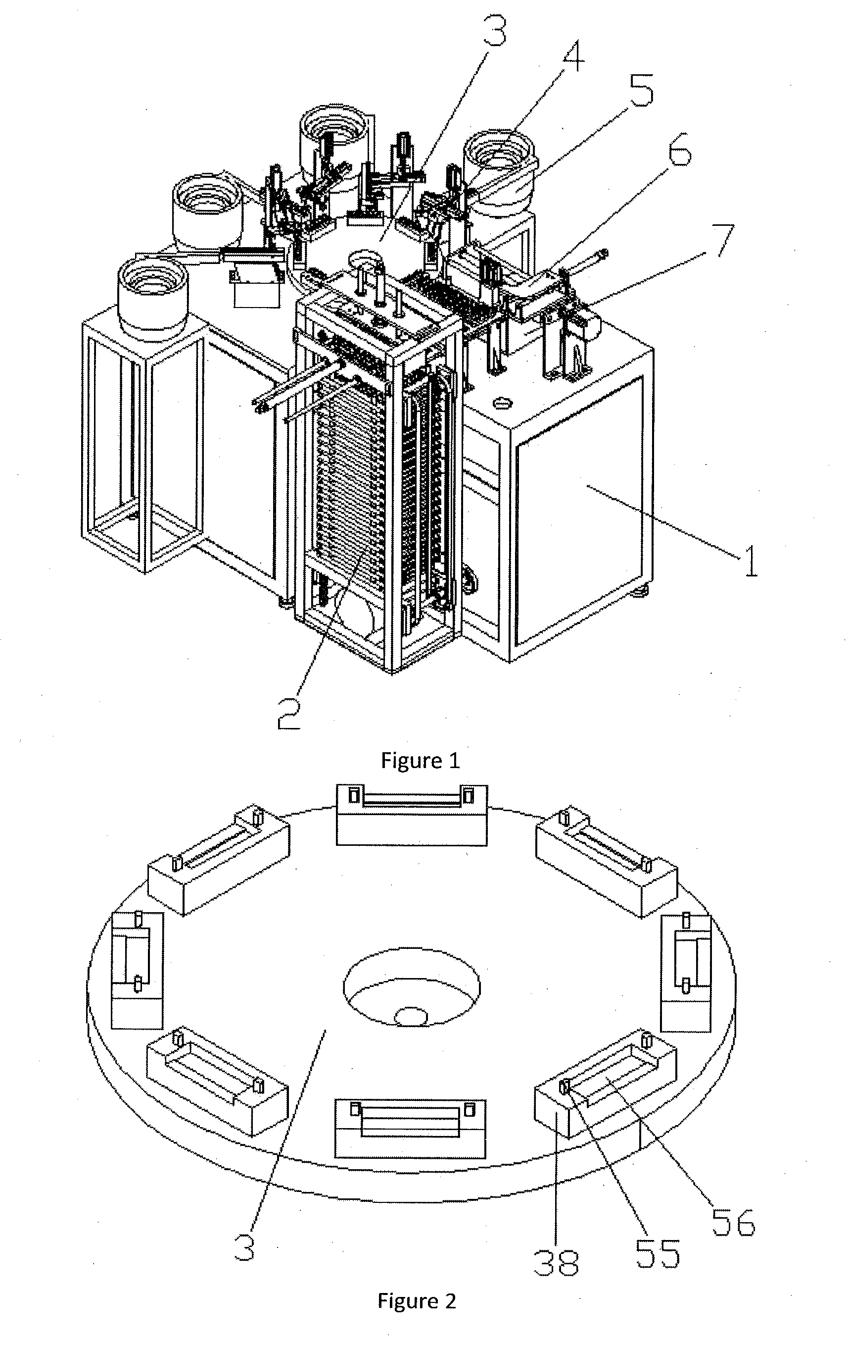
1. An automatic assembly machine for combined control button, including a frame 1, a power distribution control box, turntable 3 and turntable drive device disposed on the frame 1 fitting with each other, wherein the base fixtures 38 fitting the controller bases 48 are evenly disposed along the circumference of the turntable 3; the base fixtures 38 are respectively provided with positioning slots 56 interference fitting with the controller bases 48, and positioning rods 55 are symmetrically disposed on the left and right sides of the positioning slot 56; the positioning rods 55 fit corresponding positioning holes 50 disposed on the controller bases 48 by plugging and fitting; the front side of the frame 1 located at the right side of the turntable 3 is disposed with a base feeding mechanism 2, the rear side of the base feeding mechanism 2 located on the frame 1 is provided with a base transportation device 6 fitting with the base fixtures 38; the left side of the base transportation device 6 along the rotating direction of the turntable 3 is provided with a button assembly mechanism 4 cooperating with the base fixtures 38; the button assembly mechanism 4 cooperates with a button vibration feeding tray 5 disposed on the frame 1; all of the turntable drive device, the base feeding mechanism 2, the button assembly mechanism 4 and the button vibration feeding tray 5 are electrically connected to the power distribution control box.
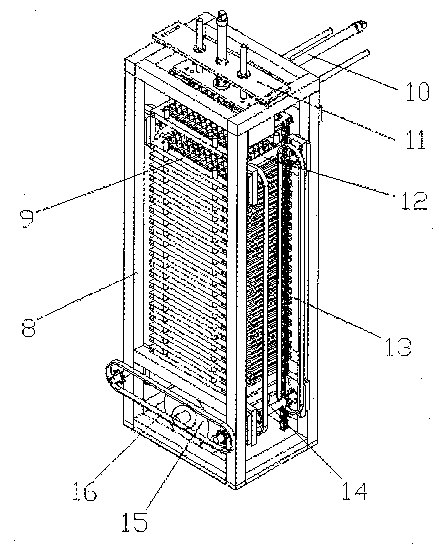
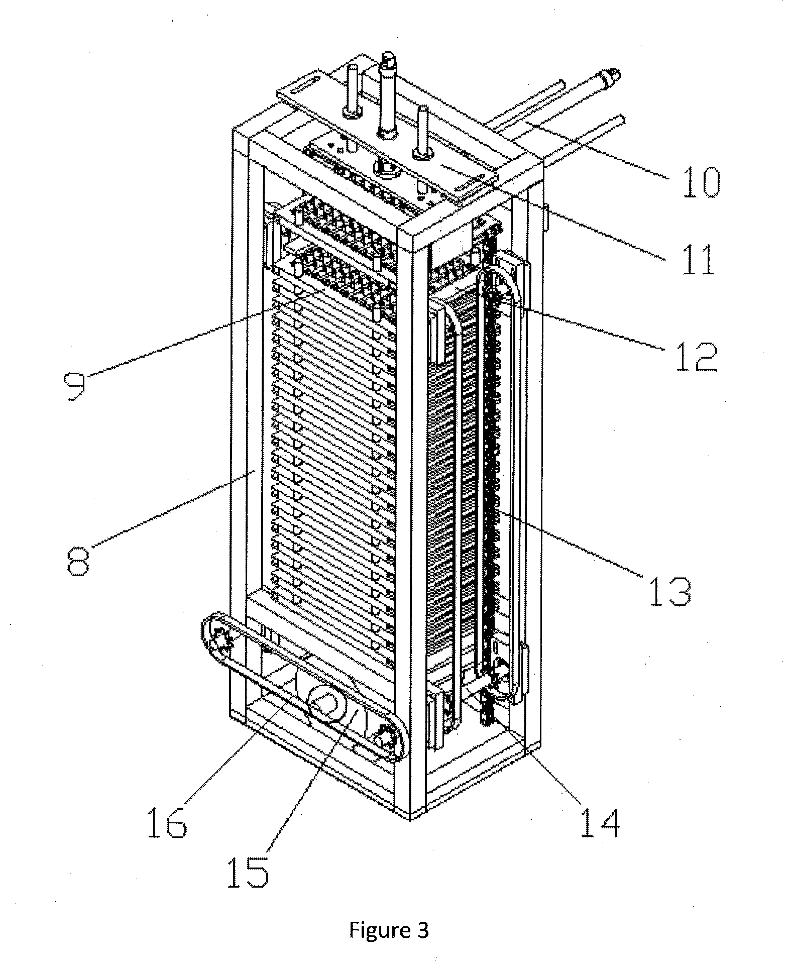
2. The automatic assembly machine for combined control button of claim 1, wherein the base feeding mechanism 2 includes a base feeding support 8 disposed on the front side of the frame 1; feeding chain wheels 13 are symmetrically disposed on the left and right sides of the base feeding support 8; the feeding chain wheel 13 is evenly provided with feeding tray supporting plates 12 fitting with the bottom of a feeding tray sets 9; the feeding chain wheel 13 is synchronously running with a driven feeding shaft 14 disposed on the base feeding support 8; the driven feeding shaft 14 is driven by a feeding motor 15 and a feeding belt pulley 16 disposed on the bottom of the base feeding support 8; the upper end of the base feeding support 8 is provided with a feeding tray clamping device 11 fitting the feeding tray sets 9, and the front side of the base feeding support 8 is provided with a feeding tray pushing device 10; the feeding tray pushing device 10 is flush with the feeding tray set 9 clamped by the feeding tray clamping device 11; all of the feeding motor 15, the feeding tray pushing device 10 and feeding tray clamping device 11 are electrically connected to the power distribution control box.
3. The automatic assembly machine for combined control button of claim 2, wherein the feeding tray set 9 includes a feeding tray base 52; the upper surface of the feeding tray base 52 is provided with storage slots 51 fitting the controller base 48; at least four sets of feeding tray separation posts 53 are symmetrically disposed on the front and rear sides of the storage slot 51 on the feeding tray base 52; the left and right sides of the feeding tray base 52 are provided with feeding tray clamping slots 54.
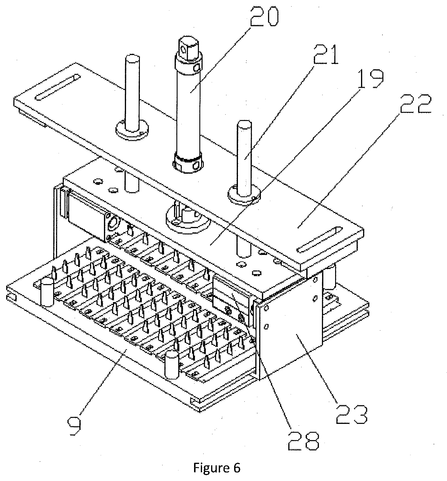
4. The automatic assembly machine for combined control button of claim 3, wherein the feeding tray clamping device 11 includes a reclaiming fixed seat 22 disposed on the upper end of the base feeding support 8; the reclaiming fixed seat 22 is disposed with a vertically downward feeding tray lifting cylinder 20; the output of the feeding tray lifting cylinder 20 is connected with a feeding tray rising plate 19, and the upper surface of the feeding tray rising plate 19 is connected with feeding tray lifting sliding poles 21, and the feeding tray lifting sliding poles 21 cooperate with the reclaiming fixed seat 22 by plugging and fitting; the left and right ends of the feeding tray rising plate 19 are provided with feeding tray clamping cylinders 28; the outer ends of the feeding tray clamping cylinder 28 is connected with L-shaped lifting plates 23, and the lower end of the lifting plates 23 are slidably fitting with the feeding tray clamping slots 54; the feeding tray lifting cylinder 20 and the feeding tray clamping cylinder 28 are all electrically connected to the power distribution control box.
5. The automatic assembly machine for combined control button of claim 4, wherein the feeding tray pushing device 10 includes a pushing fixed seat 25 disposed on the front side of the base feeding support 8, a pushing cylinder 26 is horizontally disposed on the front side of the pushing fixed seat 25, and the output of the pushing cylinder 26 is connected with a feeding tray pushing plate 24; the feeding tray pushing plate 24 is flush with the feeding tray set 9 clamped by the feeding tray clamping device 11, and a pushing sliding rod 27 cooperates with the pushing fixed seat 25 by plugging and fitting is horizontally disposed on the feeding tray pushing plate 24; the pushing cylinder 26 is electrically connected to the power distribution control box.
6. The automatic assembly machine for combined control button of claim 5, wherein the rear side of the base feeding support 8 locating at the frame 1 is disposed with a guiding supporting frame 18, the guiding supporting frame 18 is horizontally provided with a feeding tray guiding plate 17, and the rear side of the feeding tray guiding plate 17 is provided with a tilted feed slide way 7, and the upper end of the feed slide way 7 is butted to the rear end of the feeding tray guiding plate 17.
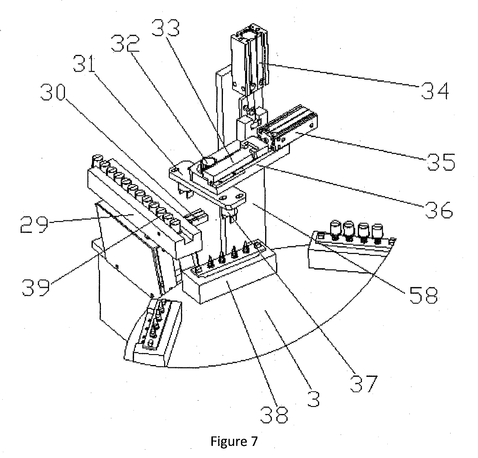
7. The automatic assembly machine for combined control button of claim 1, wherein the button assembly mechanism 4 includes a button assembly support 30 disposed on the frame 1; a vertically downward reclaiming lifting cylinder 34 is disposed on the upper end of the button assembly support 30; the output of the reclaiming lifting cylinder 34 is connected with a reclaiming lifting seat 36 slidable against the button assembly support 30; the reclaiming lifting seat 36 is horizontally provided with a horizontally movable reclaiming cylinder 35; the output of the horizontally movable reclaiming cylinder 35 is connected with a gear rack 33 slidable against the reclaiming lifting seat 36, and a gear shaft 32 engaging with the gear rack 33 is vertically disposed on the reclaiming lifting seat 36; the lower end of the gear shaft 32 passes through the reclaiming lifting seat 36 and is connected with a button reclaiming seat 31, the bottom of the button reclaiming seat 31 is symmetrically disposed with two button clamping jaws 37; the button clamping jaws 37 cooperate with buttons 39 disposed on the button distribution track 29; the reclaiming lifting cylinder 34, the horizontally movable reclaiming cylinder 35 and the button clamping jaw 37 are all electrically connected to the power distribution control box.
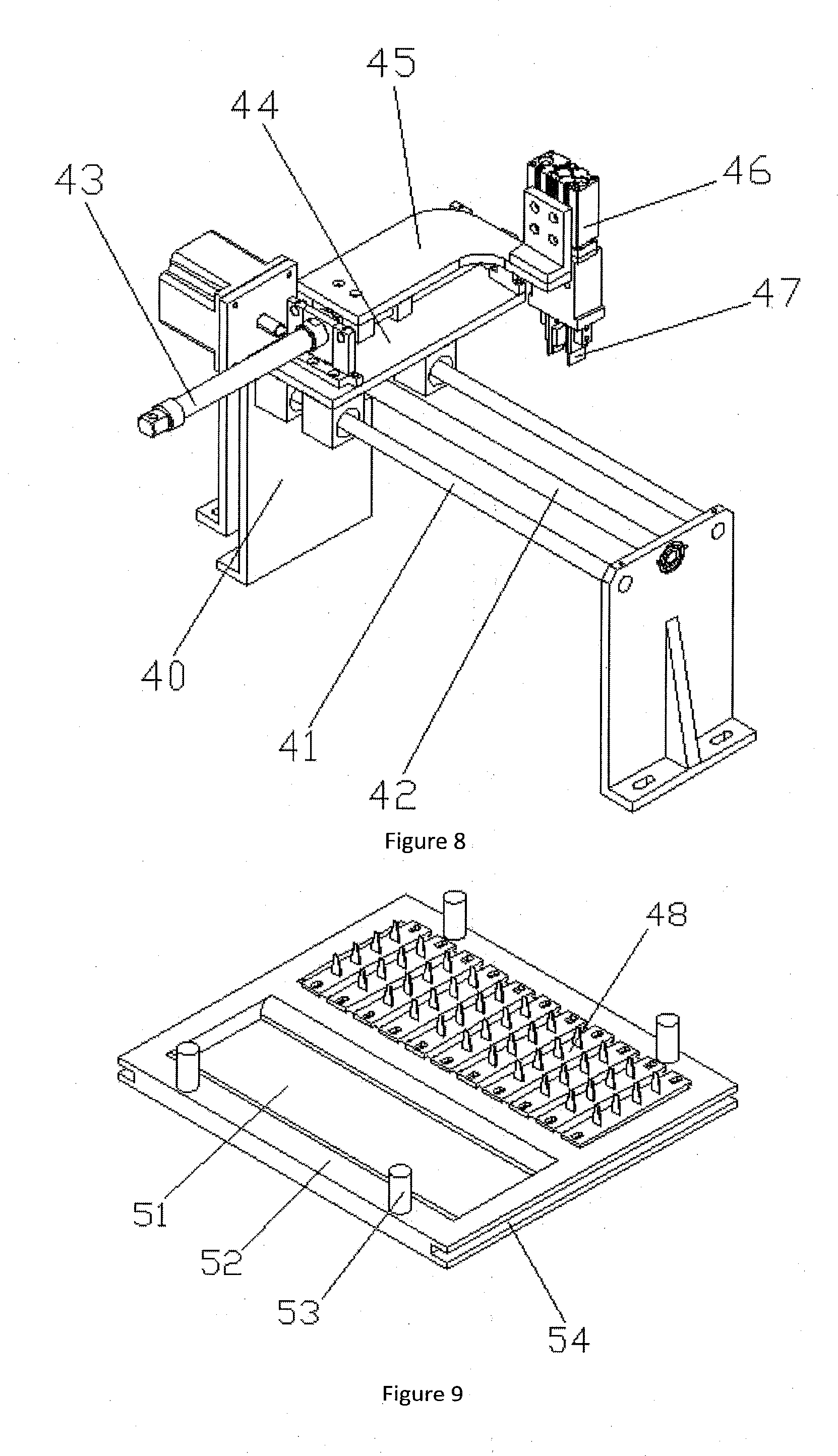
8. The automatic assembly machine for combined control button of claim 1, wherein the base transportation device 6 includes a transportation support 40 disposed on the frame 1; the transportation support 40 is horizontally provided with transportation sliding rods 41 and a transportation screw rod 42, the transportation screw rod 42 is connected with the output of the transportation servo motor 44 disposed on the transportation support 40; the transportation screw rod 42 is connected with a nut seat, which cooperates with the transportation sliding rods 41 by plugging and fitting, and the nut seat is provided with a transportation translation seat 45; a transportation translation cylinder 43 is horizontally disposed on the transportation translation seat 45, the output of the transportation translation cylinder 43 is connected with a upper reclaiming plate 46; the end of the upper reclaiming plate 46 is vertically provided with a disclaiming lift cylinder 47, and the output of the disclaiming lift cylinder 47 is mounted with a base clamping jaw 57 fitting with the controller base 48; all of the transportation servo motor 44, the transportation translation cylinder 43, the disclaiming lift cylinder 47 and the base clamping jaw 57 are electrically connected to the power distribution control box.
Description
FIELD OF THE INVENTION
[0001] The present invention relates to an automatic assembly machine, more particularly to an automatic assembly machine for a combined control button.
BACKGROUND OF THE INVENTION
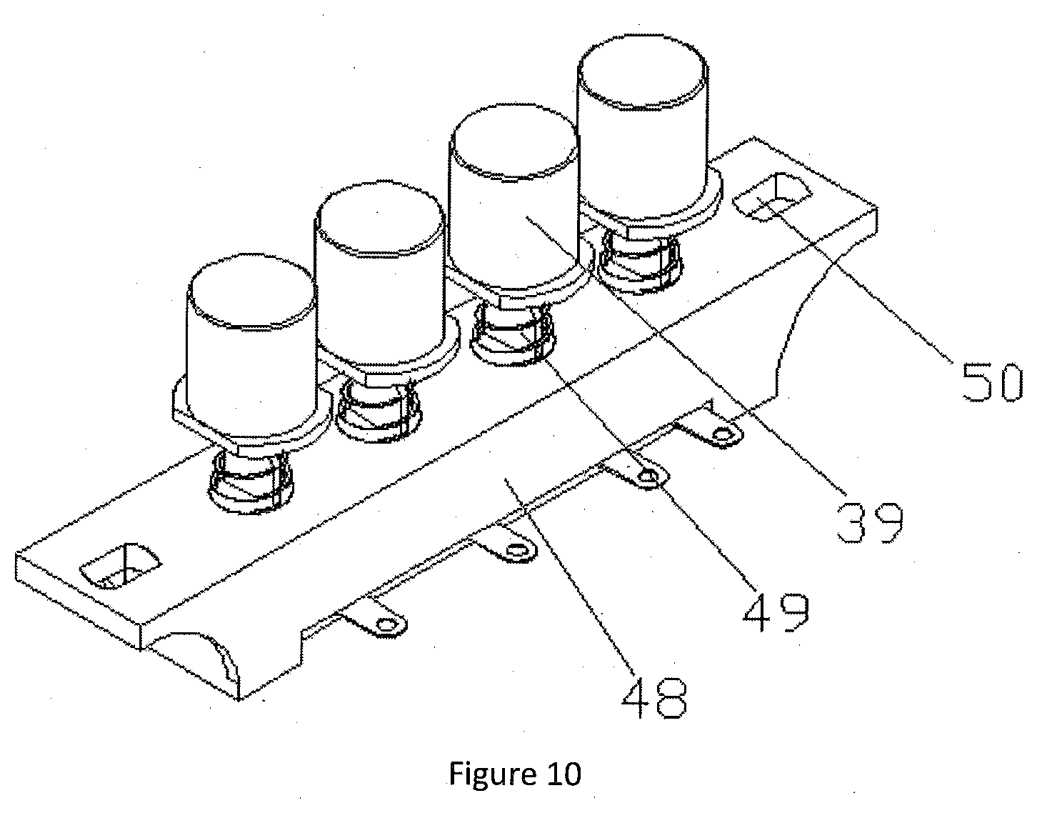
[0002] Existing combined control buttons generally consist of three parts: a controller base 48, several button sleeve rods 49, and several buttons 39, in which the button sleeve rods 49 are mounted on the controller base 48 side by side and the bottoms thereof are electrically connected to the signal end. The buttons 39 are fitted to the button sleeve rods 49 by plugging and fitting, therefore, the combined control button is assembled according to the determined relationship among above three parts. At present, the combined control buttons are generally assembled manually or by semi-automatic machines, process thereof is relatively complicated and as most of the assembly process is done manually, defects such as low production efficiency, large consumption of human resources, high labor intensity, relatively high probability of safety hazards, and high product defect rate etc are common to see.
OVERALL OBJECTIVE OF THE INVENTION
[0003] The overall objective of the present invention is to provide an automatic assembly machine for combined control button, which automatically feeds through a base feeding mechanism, accurately transports the controller base to the base fixture by the base transportation device, and continuously presses the button automatically through the button assembly mechanism. The present invention is able to effectively solve the problems of the existing combined controller adopting the manual inserting button during assembly, which has problems as low productivity, large human resource consumption, high labor intensity of the operator, high probability of relative safety hazards, and high defect rate of the electrical connector.
[0004] In order to achieve the aforenoted objective, the technical solutions adopted by the present invention are:
[0005] An automatic assembly machine for a combined control button, including a frame 1, a power distribution control box, turntable 3 and turntable drive device disposed on the frame 1 fitting with each other, wherein the base fixtures 38 fitting the controller bases 48 are evenly disposed along the circumference of the turntable 3; the base fixtures 38 are respectively provided with positioning slots 56 interference fitting with the controller bases 48, and positioning rods 55 are symmetrically disposed on the left and right sides of the positioning slot 56; the positioning rods 55 fit corresponding positioning holes 50 disposed on the controller bases 48 by plugging and fitting; the front side of the frame 1 located at the right side of the turntable 3 is disposed with a base feeding mechanism 2, the rear side of the base feeding mechanism 2 located on the frame 1 is provided with a base transportation device 6 fitting with the base fixtures 38; the left side of the base transportation device 6 along the rotating direction of the turntable 3 is provided with a button assembly mechanism 4 cooperating with the base fixtures 38; the button assembly mechanism 4 cooperates with a button vibration feeding tray 5 disposed on the frame 1; all of the turntable drive device, the base feeding mechanism 2, the button assembly mechanism 4 and the button vibration feeding tray 5 are electrically connected to the power distribution control box.
[0006] Preferably, the base feeding mechanism 2 includes a base feeding support 8 disposed on the front side of the frame 1; feeding chain wheels 13 are symmetrically disposed on the left and right sides of the base feeding support 8; the feeding chain wheel 13 is evenly provided with feeding tray supporting plates 12 fitting with the bottom of a feeding tray sets 9; the feeding chain wheel 13 is synchronously running with a driven feeding shaft 14 disposed on the base feeding support 8; the driven feeding shaft 14 is driven by a feeding motor 15 and a feeding belt pulley 16 disposed on the bottom of the base feeding support 8; the upper end of the base feeding support 8 is provided with a feeding tray clamping device 11 fitting the feeding tray sets 9, and the front side of the base feeding support 8 is provided with a feeding tray pushing device 10; the feeding tray pushing device 10 is flush with the feeding tray set 9 clamped by the feeding tray clamping device 11; all of the feeding motor 15, the feeding tray pushing device 10 and feeding tray clamping device 11 are electrically connected to the power distribution control box.
[0007] Preferably, the feeding tray set 9 includes a feeding tray base 52; the upper surface of the feeding tray base 52 is provided with a storage slot 51 fitting the controller base 48; at least four sets of feeding tray separation posts 53 are symmetrically disposed on the front and rear sides of the storage slot 51 on the feeding tray base 52; the left and right sides of the feeding tray base 52 are provided with feeding tray clamping slots 54.
[0008] Preferably, the feeding tray clamping device 11 includes a reclaiming fixed seat 22 disposed on the upper end of the base feeding support 8; the reclaiming fixed seat 22 is disposed with a vertically downward feeding tray lifting cylinder 20; the output of the feeding tray lifting cylinder 20 is connected with a feeding tray rising plate 19, and the upper surface of the feeding tray rising plate 19 is connected with feeding tray lifting sliding poles 21, and the feeding tray lifting sliding poles 21 cooperate with the reclaiming fixed seat 22 by plugging and fitting; the left and right ends of the feeding tray rising plate 19 are provided with feeding tray clamping cylinders 28; the outer ends, of the feeding tray clamping cylinder 28 is connected with L-shaped lifting plates 23, and the lower end of the lifting plates 23 are slidably fitting with the feeding tray clamping slots 54; the feeding tray lifting cylinder 20 and the feeding tray clamping cylinder 28 are all electrically connected to the power distribution control box.
[0009] Preferably, the feeding tray pushing device 10 includes a pushing fixed seat 25 disposed on the front side of the base feeding support 8, a pushing cylinder 26 is horizontally disposed on the front side of the pushing fixed seat 25, and the output of the pushing cylinder 26 is connected with a feeding tray pushing plate 24; the feeding tray pushing plate 24 is flush with the feeding tray set 9 clamped by the feeding tray clamping device 11, and a pushing sliding rod 27 cooperates with the pushing fixed seat 25 by plugging and fitting is horizontally disposed on the feeding tray pushing plate 24; the pushing cylinder 26 is electrically connected to the power distribution control box.
[0010] Preferably, the rear side of the base feeding support 8 locating at the frame 1 is disposed with a guiding supporting frame 18, the guiding supporting frame 18 is horizontally provided with a feeding tray guiding plate 17, and the rear side of the feeding tray guiding plate 17 is provided with a tilted feed slide way 7, and the upper end of the feed slide way 7 is butted to the rear end of the feeding tray guiding plate 17.
[0011] Preferably, the button assembly mechanism 4 includes a button assembly support 30 disposed on the frame 1; a vertically downward reclaiming lifting cylinder 34 is disposed on the upper end of the button assembly support 30; the output of the reclaiming lifting cylinder 34 is connected with a reclaiming lifting seat 36 slidable against the button assembly support 30; the reclaiming lifting seat 36 is horizontally provided with a horizontally movable reclaiming cylinder 35; the output of the horizontally movable reclaiming cylinder 35 is connected with a gear rack 33 slidable against the reclaiming lifting seat 36, and a gear shaft 32 engaging with the gear rack 33 is vertically disposed on the reclaiming lifting seat 36; the lower end of the gear shaft 32 passes through the reclaiming lifting seat 36 and is connected with a button reclaiming seat 31, the bottom of the button reclaiming seat 31 is symmetrically disposed with two button clamping jaws 37; the button clamping jaws 37 cooperate with buttons 39 disposed on the button distribution track 29; the reclaiming lifting cylinder 34, the horizontally movable reclaiming cylinder 35 and the button clamping jaw 37 are all electrically connected to the power distribution control box.
[0012] Preferably, the base transportation device 6 includes a transportation support 40 disposed on the frame 1; the transportation support 40 is horizontally provided with transportation sliding rods 41 and a transportation screw rod 42, the transportation screw rod 42 is connected with the output of the transportation servo motor 44 disposed on the transportation support 40; the transportation screw rod 42 is connected with a nut seat, which cooperates with the transportation sliding rods 41 by plugging and fitting, and the nut seat is provided with a transportation translation seat 45; a transportation translation cylinder 43 is horizontally disposed on the transportation translation seat 45, the output of the transportation translation cylinder 43 is connected with a upper reclaiming plate 46; the end of the upper reclaiming plate 46 is vertically provided with a disclaiming lift cylinder 47, and the output of the disclaiming lift cylinder 47 is mounted with a base clamping jaw 57 fitting with the controller base 48; all of the transportation servo motor 44, the transportation translation cylinder 43, the disclaiming lift cylinder 47 and the base clamping jaw 57 are electrically connected to the power distribution control box.
BRIEF DESCRIPTION OF DRAWINGS
[0013] FIG. 1 is a schematic perspective view of the present invention;
[0014] FIG. 2 is a schematic structural view of the turntable;
[0015] FIG. 3 is a schematic view of the feeding portion in the base feeding mechanism;
[0016] FIG. 4 is a schematic structural view of the cooperation between the feeding tray clamping, the feeding tray pushing, and the base transportation device;
[0017] FIG. 5 is a schematic structural view of the cooperation between the feeding tray clamping device and the feeding tray pushing device;
[0018] FIG. 6 is a schematic structural view of the feeding tray clamping device;
[0019] FIG. 7 is a schematic structural view of the button assembly mechanism;
[0020] FIG. 8 is a schematic structural view of the base transportation device;
[0021] FIG. 9 is a schematic structural view of the feeding tray set; and
[0022] FIG. 10 is a schematic structural view of the combined control button.
REFERENCE NUMBER KEY
[0023] The drawings include the following components: [0024] 1. Frame; [0025] 2. Base feeding mechanism; [0026] 3. Turntable; [0027] 4. Button assembly mechanism; [0028] 5. Button vibration feeding tray; [0029] 6. Base transportation device; [0030] 7. Feed slide way; [0031] 8. Base feeding support; [0032] 9. Feeding tray set; [0033] 10. Feeding tray pushing device; [0034] 11. Feeding tray clamping device; [0035] 12. Feeding tray supporting plate; [0036] 13. Feeding chain wheel; [0037] 14. Driven feeding shaft; [0038] 15. Feeding motor; [0039] 16. Feeding belt pulley; [0040] 17. Feeding tray guiding plate; [0041] 18. Guiding supporting frame; [0042] 19. Feeding tray rising plate; [0043] 20. Feeding tray lifting cylinder; [0044] 21. Feeding tray lifting sliding pole; [0045] 22. Reclaiming fixed seat; [0046] 23. Lifting plate; [0047] 24. Feeding tray pushing plate; [0048] 25. Pushing fixed seat; [0049] 26. Pushing cylinder; [0050] 27. Pushing sliding rod; [0051] 28. Feeding tray clamping cylinder; [0052] 29. Button distribution track; [0053] 30. Button assembly support; [0054] 31. Button reclaiming seat; [0055] 32. Gear shaft; [0056] 33. Gear rack; [0057] 34. Reclaiming lifting cylinder; [0058] 35. Horizontally movable reclaiming cylinder; [0059] 36. Reclaiming lifting seat; [0060] 37. Button clamping jaw; [0061] 38. Base fixture; [0062] 39. Button; [0063] 40. Transportation support; [0064] 41. Transportation sliding rod; [0065] 42. Transportation screw rod; [0066] 43. Transportation translation cylinder; [0067] 44. Transportation servo motor; [0068] 45. Transportation translation seat; [0069] 46. Upper reclaiming plate; [0070] 47. Reclaiming lifting cylinder; [0071] 48. Controller base; [0072] 49. Button sleeve rod; [0073] 50. Positioning hole; [0074] 51. Storage slot; [0075] 52. Feeding tray base; [0076] 53. Feeding tray separation post; [0077] 54. Feeding tray clamping slot; [0078] 55. Positioning rod; [0079] 56. Positioning slot; [0080] 57. Base clamping jaw.
DETAILED DESCRIPTION OF THE ILLUSTRATED EMBODIMENT
[0081] In order to make those skilled in the art understand the technical solutions of the present invention better, the present invention will be described in detail below with reference to the accompanying drawings. The description of the present section is merely exemplary and explanatory, and should not be construed as limiting the scope of the invention.
[0082] As shown in FIG. 1, the structure of the present invention is as follows:
[0083] An automatic assembly machine for combined control button, including a frame 1, a power distribution control box, turntable 3 and turntable drive device disposed on the frame 1 fitting with each other, wherein the base fixtures 38 fitting the controller bases 48 are evenly disposed along the circumference of the turntable 3; the base fixtures 38 are respectively provided with positioning slots 56 interference fitting with the controller bases 48, and positioning rods 55 are symmetrically disposed on the left and right sides of the positioning slot 56; the positioning rods 55 fit corresponding positioning holes 50 disposed on the controller bases 48 by plugging and fitting; the front side of the frame 1 located at the right side of the turntable 3 is disposed with a base feeding mechanism 2, the rear side of the base feeding mechanism 2 located on the frame 1 is provided with a base transportation device 6 fitting with the base fixtures 38; the left side of the base transportation device 6 along the rotating direction of the turntable 3 is provided with a button assembly mechanism 4 cooperating with the base fixtures 38; the button assembly mechanism 4 cooperates with a button vibration feeding tray 5 disposed on the frame 1; all of the turntable drive device, the base feeding mechanism 2, the button assembly mechanism 4 and the button vibration feeding tray 5 are electrically connected to the power distribution control box. By feeding with the base feeding mechanism 2, carrying with the base transportation device 6 precisely the controller base 48 to the base fixture 38, and pressing buttons in position continuously and automatically with the button assembly mechanism 4, it is possible to address effectively the problems occurred with the existing combined control button manual assembly, such as low production efficiency, high manpower consumption, intensive labor input, and relatively high safety hazard potentials and undesirable defective rate of the electrical connectors.
[0084] As shown in FIGS. 3 and 5, the base feeding mechanism 2 includes a base feeding support 8 disposed on the front side of the frame 1; feeding chain wheels 13 are symmetrically disposed on the left and right sides of the base feeding support 8; the feeding chain wheel 13 is evenly provided with feeding tray supporting plates 12 fitting with the bottom of a feeding tray sets 9; the feeding chain wheel 13 is synchronously running with a driven feeding shaft 14 disposed on the base feeding support 8; the driven feeding shaft 14 is driven by a feeding motor 15 and a feeding belt pulley 16 disposed on the bottom of the base feeding support 8; the upper end of the base feeding support 8 is provided with a feeding tray clamping device 11 fitting the feeding tray sets 9, and the front side of the base feeding support 8 is provided with a feeding tray pushing device 10; the feeding tray pushing device 10 is flush with the feeding tray set 9 clamped by the feeding tray clamping device 11; all of the feeding motor 15, the feeding tray pushing device 10 and feeding tray clamping device 11 are electrically connected to the power distribution control box. By driving the feeding chain wheels 13 to rotate with the feeding motor 15, and raise the feeding tray sets 9 gradually, clamping with the feeding tray clamping device 11 and pushing the feeding tray sets 9 forwards with the feeding tray pushing device 10, automatic material feeding is achieved, the operation is highly facilitated, and working time is shortened.
[0085] As shown in FIG. 9, the feeding tray set 9 includes a feeding tray base 52; the upper surface of the feeding tray base 52 is provided with storage slots 51 fitting the controller base 48; at least four sets of feeding tray separation posts 53 are symmetrically disposed on the front and rear sides of the storage slot 51 on the feeding tray base 52; the left and right sides of the feeding tray base 52 are provided with feeding tray clamping slots 54. With the storage slots 51, it is possible to hold several sets of controller bases 48, and with the tray separation posts 53, it is possible to keep a distance between feeding tray bases 52, and with the feeding tray clamping slots 54, clamping the feeding tray sets 9 with the feeding tray clamping device 11 is greatly facilitated.
[0086] As shown in FIGS. 5 and 6, the feeding tray clamping device 11 includes a reclaiming fixed seat 22 disposed on the upper end of the base feeding support 8; the reclaiming fixed seat 22 is disposed with a vertically downward feeding tray lifting cylinder 20; the output of the feeding tray lifting cylinder 20 is connected with a feeding tray rising plate 19, and the upper surface of the feeding tray rising plate 19 is connected with feeding tray lifting sliding poles 21, and the feeding tray lifting sliding poles 21 cooperate with the reclaiming fixed seat 22 by plugging and fitting; the left and right ends of the feeding tray rising plate 19 are provided with feeding tray clamping cylinders 28; the outer ends of the feeding tray clamping cylinder 28 is connected with L-shaped lifting plates 23, and the lower end of the lifting plates 23 are slidably fitting with the feeding tray clamping slots 54; the feeding tray lifting cylinder 20 and the feeding tray clamping cylinder 28 are all electrically connected to the power distribution control box. By lifting the lifting plates 23 with the feeding tray clamping cylinders 28, and with the engagement between the lifting plates 23 and the feeding tray clamping slots 54, it is possible to ensure the feeding trays stay stable during lifting, in the meantime, with the height of the feeding tray controlled by the feeding tray lifting cylinder 20, the position of feeding trays is accurate.
[0087] As shown in FIG. 5, the feeding tray pushing device 10 includes a pushing fixed seat 25 disposed on the front side of the base feeding support 8, a pushing cylinder 26 is horizontally disposed on the front side of the pushing fixed seat 25, and the output of the pushing cylinder 26 is connected with a feeding tray pushing plate 24; the feeding tray pushing plate 24 is flush with the feeding tray set 9 clamped by the feeding tray clamping device 11, and a pushing sliding rod 27 cooperates with the pushing fixed seat 25 by plugging and fitting is horizontally disposed on the feeding tray pushing plate 24; the pushing cylinder 26 is electrically connected to the power distribution control box. By pushing the feeding tray sets 9 with the pushing cylinder 26, loading of the controller bases is facilitated.
[0088] As shown in FIGS. 4 and 5, the rear side of the base feeding support 8 locating at the frame 1 is disposed with a guiding supporting frame 18, the guiding supporting frame 18 is horizontally provided with a feeding tray guiding plate 17, and the rear side of the feeding tray guiding plate 17 is provided with a tilted feed slide way 7, and the upper end of the feed slide way 7 is butted to the rear end of the feeding tray guiding plate 17. By providing the feeding tray guiding plate 17, the feeding tray sets can slide on the feeding tray guiding plate under the operation of the pushing cylinder 16, which facilitates feeding of controller bases 48, and the feeding tray sets 9 can be delivered to the feed slide way 7 and slide down.
[0089] As shown in FIG. 7, the button assembly mechanism 4 includes a button assembly support 30 disposed on the frame 1; a vertically downward reclaiming lifting cylinder 34 is disposed on the upper end of the button assembly support 30; the output of the reclaiming lifting cylinder 34 is connected with a reclaiming lifting seat 36 slidable against the button assembly support 30; the reclaiming lifting seat 36 is horizontally provided with a horizontally movable reclaiming cylinder 35; the output of the horizontally movable reclaiming cylinder 35 is connected with a gear rack 33 slidable against the reclaiming lifting seat 36, and a gear shaft 32 engaging with the gear rack 33 is vertically disposed on the reclaiming lifting seat 36; the lower end of the gear shaft 32 passes through the reclaiming lifting seat 36 and is connected with a button reclaiming seat 31, the bottom of the button reclaiming seat 31 is symmetrically disposed with two button clamping jaws 37; the button clamping jaws 37 cooperate with buttons 39 disposed on the button distribution track 29; the reclaiming lifting cylinder 34, the horizontally movable reclaiming cylinder 35 and the button clamping jaw 37 are all electrically connected to the power distribution control box. By clamping the button 39 inside the button distribution track 29 with the button clamping jaw 37, and lifting the button with the reclaiming lifting cylinder 34 and putting into the base fixture 38, and driving the gear rack 33 with the horizontally movable reclaiming cylinder 35 and in turn the gear shaft 32, the 2 button clamping jaws 37 can work continuously, the buttons are clamped while assembled in the same time, and production efficiency is improved.
[0090] As shown in FIG. 8, the base transportation device 6 includes a transportation support 40 disposed on the frame 1; the transportation support 40 is horizontally provided with transportation sliding rods 41 and a transportation screw rod 42, the transportation screw rod 42 is connected with the output of the transportation servo motor 44 disposed on the transportation support 40; the transportation screw rod 42 is connected with a nut seat, which cooperates with the transportation sliding rods 41 by plugging and fitting, and the nut seat is provided with a transportation translation seat 45; a transportation translation cylinder 43 is horizontally disposed on the transportation translation seat 45, the output of the transportation translation cylinder 43 is connected with a upper reclaiming plate 46; the end of the upper reclaiming plate 46 is vertically provided with a disclaiming lift cylinder 47, and the output of the disclaiming lift cylinder 47 is mounted with a base clamping jaw 57 fitting with the controller base 48; all of the transportation servo motor 44, the transportation translation cylinder 43, the disclaiming lift cylinder 47 and the base clamping jaw 57 are electrically connected to the power distribution control box. By clamping the controller base 48 with the base clamping jaw 57, and lifting with the reclaiming lifting cylinder 47, under the accurate operation of the transportation translation cylinder 43 and the transportation servo motor 44, the controller base can be placed accurately inside the positioning slot 56 in the base fixture 38.
[0091] When in use, first put buttons 39 in the button feed vibrating plate 5 and then the base feeding mechanism 2 automatically feeds. The feeding motor 15 drives the feeding chain wheels 13 to rotate, and the feeding tray sets 9 rise gradually, and is individually clamped by the feeding tray clamping device 11. The feeding tray clamping cylinder 28 pulls the lifting plates 23 up and by cooperating with the feeding tray clamping slots 54 it is possible to ensure the tray remains stable when clamping. Meanwhile, the height of the tray is controlled by the feeding tray lifting cylinder 20, and then the feeding tray set 9 is fed forward to the feeding tray guiding plate 17 by the feeding tray pushing device 10, the base clamping jaw 57 clamps the controller base 48 individually and lift it with the reclaiming lifting cylinder 47. The controller base 48 is accurately placed into the positioning slot 56 of the base fixture 38 by the precise movement of the transportation translation cylinder 43 and the transportation servo motor 44. Then the turntable 3 rotates counterclockwise to under the four sets of button assembly mechanisms 4, by clamping buttons 39 in the button distribution track 29 with the button clamping jaw 37, and lifting and placing them on the base fixture 38 with the reclaiming lifting cylinder 34 and driving the gear rack 33 and in turn the gear shaft 32 to have the two button clamping jaws 37 working continuously with the horizontally movable reclaiming cylinder 34, buttons 39 are reclaimed and assembled at the same time. Rotate the base fixture 38 to the left side of the base transportation device 6 when buttons 39 are assembled; clamp the assembled controller base 48 with the base clamping jaw 57 and place it back into the feeding tray set 9 and discharge the feeding tray set 9 fully loaded with the assembled product along the discharging sliding track with the pushing cylinder 26.
[0092] In the present invention, it should be noted that the term "includes", "including" or any other variants thereof is intended to encompass a non-exclusive inclusion, such that a process, method, article, or device that comprises a plurality of elements includes not only those elements. It also includes other elements that are not explicitly listed, or elements that are inherent to such a process, method, item, or device.
[0093] The principles and embodiments of the present invention have been described with reference to specific examples. The foregoing description of the embodiments is only for the purpose of understanding the method of the present invention and the core idea thereof. The above description is only a preferred embodiment of the present invention, and it should be noted that Due to the finiteness of the textual expression and the infinitely specific structure objectively, it is possible for those skilled in the art to make some improvements, refinements or changes without departing from the principles of the present invention. The above technical features may be combined in an appropriate manner; these improvements, modifications, variations or combinations, or the direct application of the inventive concepts and technical solutions to other applications without modification, are considered to be the scope of protection of the present invention.
* * * * *
D00000
D00001
D00002
D00003
D00004
D00005
D00006
D00007
XML
uspto.report is an independent third-party trademark research tool that is not affiliated, endorsed, or sponsored by the United States Patent and Trademark Office (USPTO) or any other governmental organization. The information provided by uspto.report is based on publicly available data at the time of writing and is intended for informational purposes only.
While we strive to provide accurate and up-to-date information, we do not guarantee the accuracy, completeness, reliability, or suitability of the information displayed on this site. The use of this site is at your own risk. Any reliance you place on such information is therefore strictly at your own risk.
All official trademark data, including owner information, should be verified by visiting the official USPTO website at www.uspto.gov. This site is not intended to replace professional legal advice and should not be used as a substitute for consulting with a legal professional who is knowledgeable about trademark law.