Cleaning Tool
LEE; In-Hwan ; et al.
U.S. patent application number 16/316947 was filed with the patent office on 2019-12-26 for cleaning tool. This patent application is currently assigned to 3M Innovative Properties Company. The applicant listed for this patent is 3M INNOVATIVE PROPERTIES COMPANY. Invention is credited to Sang-Won EUN, In-Hwan LEE.
| Application Number | 20190387948 16/316947 |
| Document ID | / |
| Family ID | 59383652 |
| Filed Date | 2019-12-26 |


| United States Patent Application | 20190387948 |
| Kind Code | A1 |
| LEE; In-Hwan ; et al. | December 26, 2019 |
CLEANING TOOL
Abstract
The present disclosure relates to a cleaning tool (10) capable of easily attaching and detaching for a web (D). Particularly, in accordance with one embodiment of the present disclosure, the cleaning tool (10) includes a handle (200) configured to be grippable by a user, a body (100) having one side to which the handle (200) is pivotably connected and the other side providing an attachment surface to and from which a web (D) for cleaning is attachable and detachable, and a pushing unit (300) provided at the handle (200) to be movable therealong, wherein when the web (D) is attached to the attachment surface, the pushing unit (300) is movable along the handle (200) to separate the web (D) from the attachment surface.
| Inventors: | LEE; In-Hwan; (Gyeonggi-do, KR) ; EUN; Sang-Won; (Gyeonggi-do, KR) | ||||||||||
| Applicant: |
|
||||||||||
|---|---|---|---|---|---|---|---|---|---|---|---|
| Assignee: | 3M Innovative Properties
Company St. Paul MN |
||||||||||
| Family ID: | 59383652 | ||||||||||
| Appl. No.: | 16/316947 | ||||||||||
| Filed: | July 12, 2017 | ||||||||||
| PCT Filed: | July 12, 2017 | ||||||||||
| PCT NO: | PCT/US2017/041679 | ||||||||||
| 371 Date: | January 10, 2019 |
| Current U.S. Class: | 1/1 |
| Current CPC Class: | A47L 13/254 20130101; A47L 13/46 20130101; A47L 13/257 20130101; A47L 13/256 20130101 |
| International Class: | A47L 13/257 20060101 A47L013/257; A47L 13/46 20060101 A47L013/46; A47L 13/256 20060101 A47L013/256 |
Foreign Application Data
| Date | Code | Application Number |
|---|---|---|
| Jul 13, 2016 | KR | 10-2016-0088561 |
Claims
1. A cleaning tool, comprising: a handle; a body having one side to which the handle is pivotably connected and the other side providing an attachment surface to and from which a web for cleaning is attachable and detachable; and a pushing unit provided at the handle to be movable therealong, wherein, when the web is attached to the attachment surface, the pushing unit is movable along the handle to separate the web from the attachment surface.
2. The cleaning tool of claim 1, further comprising a rod separably connected to the handle, wherein the body is connected to the one side of the handle, and the rod is connected to the other side of the handle.
3. The cleaning tool of claim 1, wherein the pushing unit includes: a pushable button; and a push bar positioned inside the handle and connected to the button, wherein, when the web is attached to the attachment surface and the button pushes the push bar, the push bar moves toward an outward side of the handle to separate the web from the attachment surface.
4. The cleaning tool of claim 3, further comprising: an insertion depression formed at the handle, wherein the push bar is insertable into the insertion depression; and a through-hole formed at the body, wherein the through-hole communicates with the insertion depression to enable the push bar to pass through the through-hole.
5. The cleaning tool of claim 4, wherein the pushing unit further comprises a sliding guide provided at one surface of the push bar, and wherein the pushable button is formed at an end portion of the sliding guide.
6. The cleaning tool of claim 5, further comprising a guide slot formed at the handle and facing the insertion depression, wherein when the push bar moves inside the handle, the sliding guide moves along the guide slot.
7. The cleaning tool of claim 4, wherein the body includes a pivot restriction part provided adjacent to the through-hole, wherein the pushing unit includes a push bar latch which is formed at an end portion of the push bar and is engageable with the pivot restriction part, and wherein when the push bar latch and the pivot restriction part are engaged with each other, pivoting of the handle is restricted.
8. The cleaning tool of claim 7, wherein the push bar latch is shaped like a groove with a concave end at the end portion of the push bar, and wherein the pivot restriction part includes a protrusion which is engageable with the push bar latch.
9. The cleaning tool of claim 7, wherein when the handle is pivoted by a predetermined angle that is less than 90 degrees with respect to the body, the push bar latch is engageable with the pivot restriction part.
10. The cleaning tool of claim 9, wherein the predetermined angle is 45 degrees.
11. The cleaning tool of claim 4, wherein the push bar is selectively locatable among a first position, a second position at which pivoting of the handle is restrictable, and a third position at which, when the web is attached to the attachment surface, the push bar passes through the through-hole to separate the web from the body.
12. The cleaning tool of claim 11, further comprising: one or more first grooves formed at an inner side surface of the handle; and or more second grooves formed at the push bar, engageable with the one or more first grooves, wherein when the one or more first grooves and the one or more second grooves are engaged with one another, the push bar is located in at least one of the first position, the second position, and the third position.
13. The cleaning tool of claim 12, wherein the one or more second grooves respectively includes a first recess, a second recess, and a third recess, each of which is disposed along a direction in which the push bar moves and is engageable with one of the one or more first grooves, and wherein the first recess and a protrusion of one of the one or more first grooves are engaged with each other when the push bar is located at the first position, the second recess and the protrusion are engaged with each other when the push bar is located at the second position, and the third recess and the protrusion are engaged with each other when the push bar is located at the third position.
14. The cleaning tool of claim 11, wherein the body includes a pivot restriction part formed at one side of a circumference of the through-hole, wherein the pushing unit includes a push bar latch formed at an end portion of the push bar and is selectively engaged with the pivot restriction part, and wherein when the push bar latch and the pivot restriction part are engaged with each other, pivoting of the handle is restricted while the push bar is located at the second position.
15. The cleaning tool of claim 1, further comprising a hook formed at the attachment surface and configured to couple the web with the body, wherein the hook comprises: a head portion having an upper surface with a rounded shape; and a pillar portion connected to a lower surface of the head portion, wherein the lower surface of the head portion is configured to have an area that is greater than that of a jointed surface of the pillar portion, and wherein when the web is gripped by the hook, the head portion digs into a surface of the web and is then hooked to the web.
16. The cleaning tool of claim 1, wherein at least a portion of the handle includes rubber.
Description
TECHNICAL FIELD
[0001] The present disclosure relates to a cleaning tool capable of easily attaching and detaching a web.
BACKGROUND
[0002] Various kinds of cleaning tools which are used by consumers exist. Examples of cleaning tools include sponges, mops, brooms, brushes, and the like. In addition to such cleaning tools, many other products have been used for a long time. To satisfy various consumers' needs for easy use, hygiene, reduction of the risk of injury to the user while cleaning, and the like regarding such cleaning tools, research to improve the cleaning tools has been consistently carried out from the past to the present.
[0003] Meanwhile, cleaning tools have various forms and functions according to places and situations in which the cleaning tools are used. Among these places and situations, in a place such as a bathroom where there is a lot of moisture and thus pollutants, such as bacteria, fungi, and the like, are frequently generated on wall surfaces, the pollutants may be removed from the wall surfaces by applying a detergent to a surface of a web, which can be made from, for example, a nonwoven fabric material, and rubbing the wall surfaces with the web. In recent years, a disposable toilet bowl scrubber (DTBS) web, which is manufactured to release a detergent when brought into contact with moisture or damp air without the detergent being applied to a surface of a web, was also released into the market. When using such a web, a user should grip the web while wearing rubber gloves on his or her hands, or should clean using a tool which enables the web to be attached thereto, and the reason for that is that, when a cleaning detergent applied to the web comes into contact with the body of the user, the cleaning detergent may adversely affect the skin of the user that comes into contact with the cleaning detergent.
[0004] A cleaning tool, which is configured to enable a web to be attached thereto and to be used, generally includes a pipe type handle to enable a user to hold the cleaning tool with his or her hands, and is provided with an attachment part to which a web is attachable at another portion of the cleaning tool except for the pipe type handle. Also, a web, which is gripped at the cleaning tool, may be contaminated when used for a long time, and thus the contaminated web should be replaced, and for this purpose, the attachment part may be configured to enable the web to be attached thereto and detached therefrom.
[0005] In a typical cleaning tool using a web, a user should hold a handle with one hand and seize a contaminated web with the other hand when separating the contaminated web from the typical cleaning tool to separate the contaminated web therefrom. Consequently, there is an inconvenience in that the hands of the user are contaminated while separating the contaminated web or that the user should wear gloves to prevent the contamination of his or her hands.
[0006] Also, because the cleaning tool should be configured to include both the handle and the attachment part configured to enable a web to be attached thereto and detached therefrom, a structure of the cleaning tool is somewhat complicated and a manufacturing process thereof is not simplified, causing manufacturing costs to become unnecessarily excessive and process time unnecessarily consumed during the manufacturing process.
SUMMARY
[0007] In accordance with one aspect of the present disclosure, a cleaning tool capable of easily attaching and detaching a web may be provided. The cleaning tool includes a handle configured to be grippable by a user, a body having one side to which the handle is pivotably connected and the other side providing an attachment surface to and from which a web for cleaning is attachable and detachable, and a pushing unit provided at the handle to be movable therealong, wherein, when the web is attached to the attachment surface, the pushing unit is movable along the handle to separate the web from the attachment surface.
[0008] In one embodiment, the cleaning tool may further include a rod separably connected to the handle, wherein the body is connected to the one side of the handle and the rod is connected to the other side of the handle.
[0009] In one embodiment, the pushing unit includes a button provided to be pushable by a hand of the user, and a push bar accommodated inside the handle and connected to the button, and, when the web is attached to the attachment surface and the button pushes the push bar, the push bar moves toward an outward side of the handle to separate the web from the attachment surface.
[0010] In one embodiment, an insertion depression into which the push bar is insertable is formed at the handle, and a through-hole is formed at the body and communicates with the insertion depression to enable the push bar to pass through the through-hole.
[0011] In one embodiment, the pushing unit further includes a sliding guide which is provided at one surface of the push bar, and the button is formed at an end portion of the sliding guide.
[0012] In one embodiment, a guide slot facing the insertion depression is formed at the handle, and, when the push bar moves inside the handle, the sliding guide moves along the guide slot.
[0013] In one embodiment, the body includes a pivot restriction part which is provided to be close to the through-hole, the pushing unit includes a push bar latch which is formed at an end portion of the push bar and is engageable with the pivot restriction part, and, when the push bar latch and the pivot restriction part are engaged with each other, pivoting of the handle is restricted.
[0014] In one embodiment, the push bar latch has a shape of a groove which is formed to be concave from the end portion of the push bar, and the pivot restriction part includes a protrusion which is engageable with the push bar latch.
[0015] In one embodiment, when the handle is pivoted by a predetermined angle that is less than 90 degrees with respect to the body, the push bar latch enters into a state of being engageable with the pivot restriction part.
[0016] In one embodiment, the predetermined angle is 45 degrees.
[0017] In one embodiment, the push bar is selectively locatable at one position among a first position, a second position at which the pivoting of the handle is restrictable, and a third position at which, when the web is attached to the attachment surface, the push bar passes through the through-hole to separate the web from the body.
[0018] In one embodiment, the cleaning tool further includes one or more first grooves formed in an inner side surface of the handle and one or more second grooves engageable with the one or more first grooves formed in the push bar. When the one or more first grooves and the one or more second grooves are engaged with one another, the push bar is located at least one position among the first position, the second position, and the third position.
[0019] In one embodiment, the one or more second grooves respectively include a first recess, a second recess, and a third recess, each of which is disposed along a direction in which the push bar moves and is engageable with one of the one or more first grooves. The first recess and a protrusion of one of the one or more first grooves are engaged with each other when the push bar is located at the first position, the second recess and the protrusion are engaged with each other when the push bar is located at the second position, and the third recess and the protrusion are engaged with each other when the push bar is located at the third position.
[0020] In one embodiment, the body includes the pivot restriction part formed at one side of a circumference of the through-hole, the pushing unit includes the push bar latch formed at the end portion of the push bar and is selectively engaged with the pivot restriction part. The push bar latch is formed at the end portion of the push bar and is selectively engaged with the pivot restriction part. When the push bar latch and the pivot restriction part are engaged with each other, the pivoting of the handle is restricted while the push bar is located at the second position.
[0021] In one embodiment, the cleaning tool further includes a hook configured to couple the web with the body. The hook is formed at the attachment surface and includes a head portion having an upper surface of a rounded shape and a pillar portion connected to a lower surface of the head portion. The lower surface of the head portion is configured to have an area that is greater than that of a jointed surface of the pillar portion. When the web is gripped by the hook, the head portion digs into a surface of the web and is then hooked to the web.
[0022] In one embodiment, at least a portion of the handle is configured to be grippable by the user, and includes rubber.
[0023] In accordance with embodiments of the present disclosure, there are effects in which a contaminated web may be conveniently separated from a cleaning tool with only one hand of a user, and further a manufacturing process may be simplified.
BRIEF DESCRIPTION OF DRAWINGS
[0024] FIG. 1 is a perspective view illustrating an attachment of a web to a cleaning tool according to one embodiment of the present disclosure.
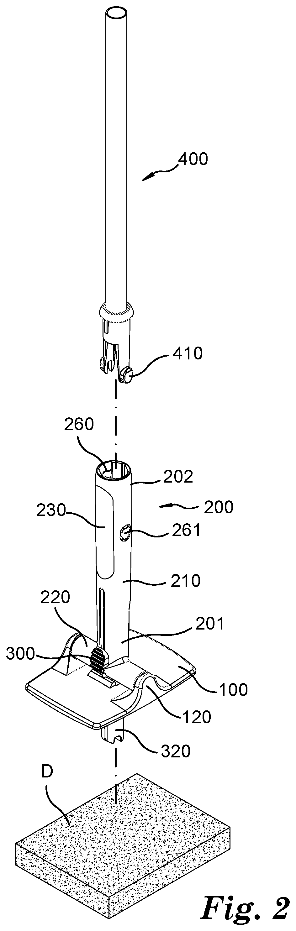
[0025] FIG. 2 is a perspective view illustrating a separation of the web and a rod from the cleaning tool of FIG. 1.
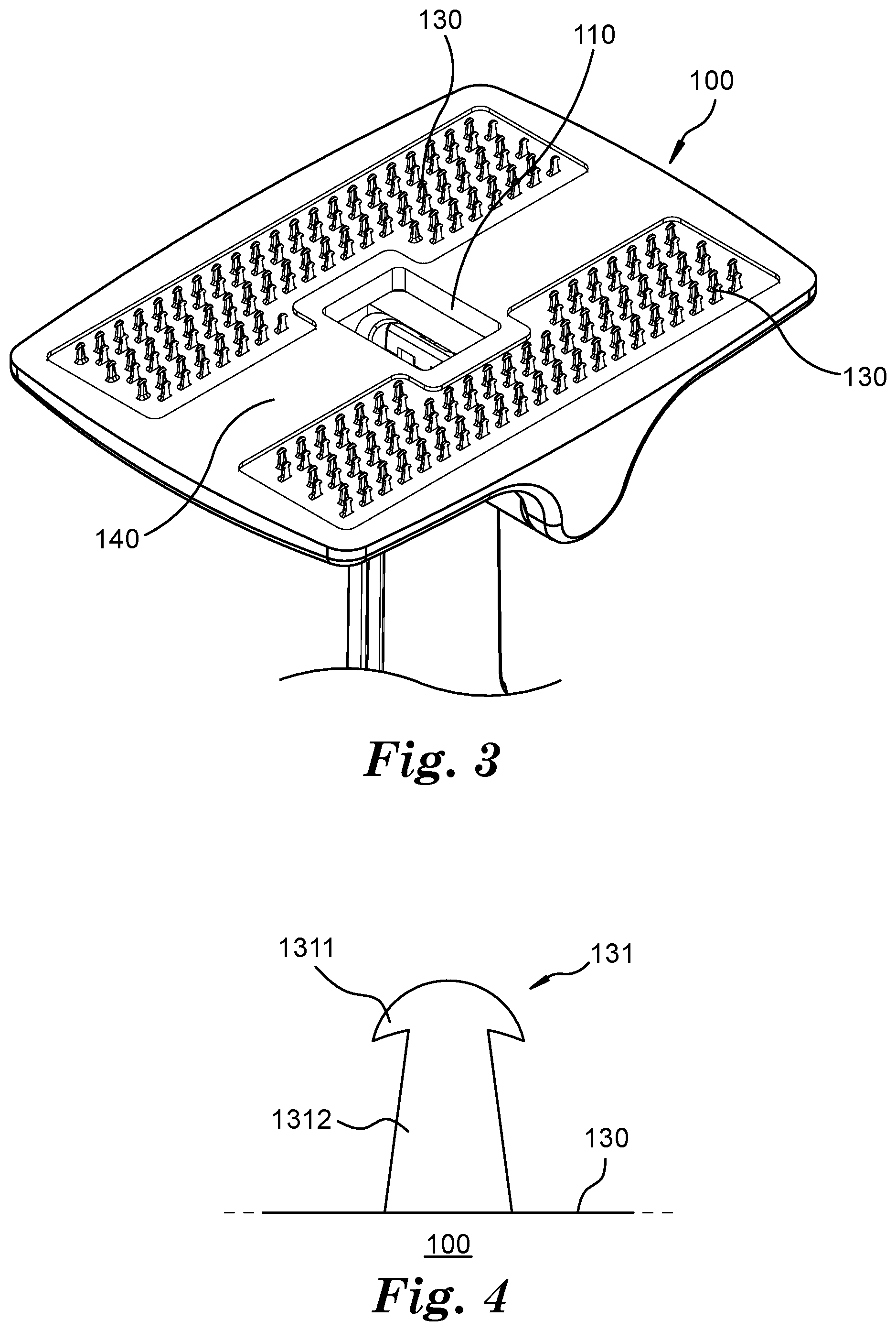
[0026] FIG. 3 is a perspective view illustrating a shape of an attachment surface of a body of FIG. 1.
[0027] FIG. 4 is a lateral view illustrating a shape of a hook of FIG. 3.
[0028] FIG. 5 is a perspective view of a cross section of a handle of FIG. 1.
[0029] FIG. 6A is a perspective view of an upper surface of a push bar of FIG. 1.
[0030] FIG. 6B is a perspective view of a lower surface of the push bar of FIG. 1.
[0031] FIG. 7 is a diagram illustrating a case in which the push bar of FIG. 1 is located at a first position.
[0032] FIG. 8 is a diagram illustrating a case in which the push bar of FIG. 1 is located at a second position.
[0033] FIG. 9 is a diagram illustrating a case in which the push bar of FIG. 1 is located at a third position.
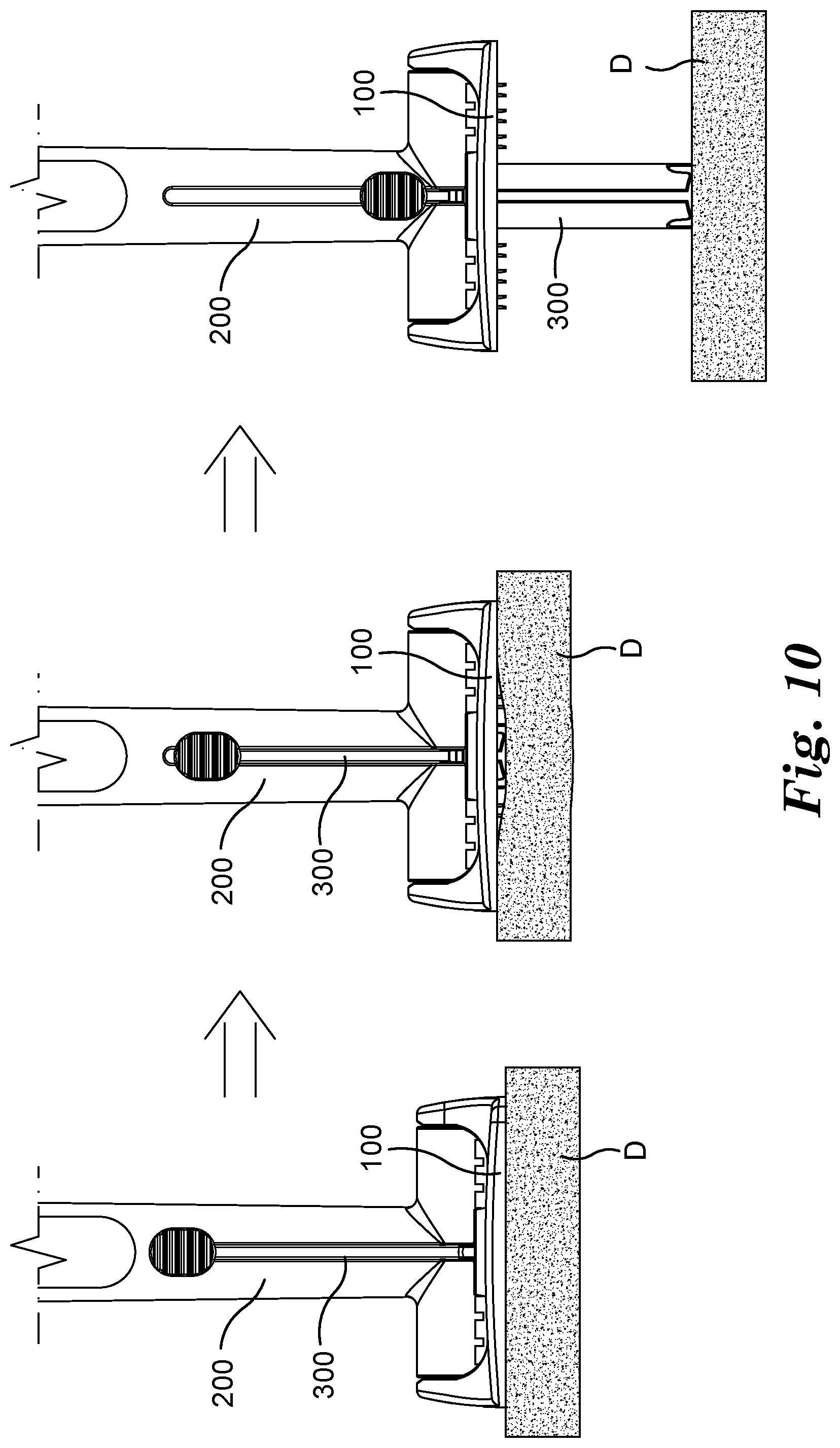
[0034] FIG. 10 is a diagram for describing a procedure in which a web gripped at the cleaning tool of FIG. 1 is separated therefrom by a pushing unit.
DETAILED DESCRIPTION
[0035] Hereinafter, a concrete embodiment for implementing the spirit of the present disclosure will be described in detail with reference to the accompanying drawings. Here, it should be noted that the drawings are not constantly illustrated to scale for convenience of a description. Also, when a detailed description of related known configurations and functions is determined to obscure the gist of the present disclosure in the following description of the present disclosure, the detailed description thereof will be omitted.
[0036] FIG. 1 is a perspective view illustrating an attachment of a web to a cleaning tool according to one embodiment of the present disclosure.
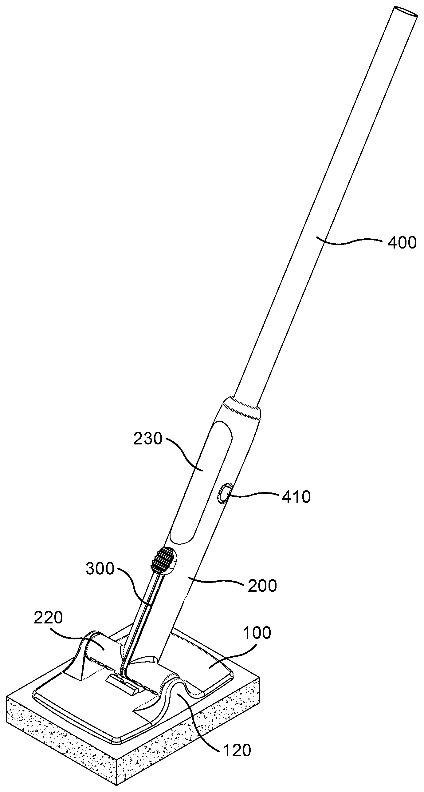
[0037] Referring to FIG. 1, a cleaning tool 10 according to one embodiment of the present disclosure may be used in a state in which a web D is attached to the cleaning tool 10, and a user may rub the web D against a portion, such as a wall surface and the like, which requires cleaning so that cleaning may be performed by a detergent which is applied to the web D or released therefrom. For this purpose, the cleaning tool 10 includes a body 100 having an attachment surface configured to enable the web D to be attached thereto and detached therefrom, a handle 200 configured to be grippable by the user, a pushing unit 300 configured to separate the web D, which is attached to the attachment surface of the body 100, from the attachment surface, and a rod 400 connected to the handle 200 at an opposite side with respect to the body 100.
[0038] Here, the web D may be configured with a member made of a nonwoven fabric material, or with a foam including a sponge, a disposable toilet bowl scrubber (DTBS), and the like, and it may be used by a detergent being applied to a surface of the web D or may be manufactured in a form in which a solid detergent is coated on the surface thereof. Also, in the case of the web D manufactured in a form in which the solid detergent is coated on the surface of the web D, a cleaner ingredient may be contained in the solid detergent, and such a cleaner ingredient may be, for example, one among calcium carbonate, potassium carbonate, sodium carbonate, sodium bicarbonate, and sodium metasilicate. Such a web D may be easily attached to the cleaning tool 10 by a hook 131, which will be described below, formed at the cleaning tool 10, and may be easily separated from the cleaning tool 10 by a user simply pushing the attached web D in a direction receding from the hook 131.
[0039] Hereinafter, a detailed configuration of such a cleaning tool 10 will be described with reference to FIGS. 2 to 10. FIG. 2 is a perspective view illustrating a separation of the web D and the rod 400 from the cleaning tool 10 of FIG. 1, FIG. 3 is a perspective view illustrating a shape of the attachment surface of the body 100 of FIG. 1, FIG. 4 is a lateral view illustrating a shape of the hook 131 of FIG. 3, FIG. 5 is a perspective view of a cross section of the handle 200 of FIG. 1, FIG. 6A is a perspective view of an upper surface of a push bar of FIG. 1, FIG. 6B is a perspective view of a lower surface of the push bar, FIG. 7 is a diagram illustrating a case in which the push bar of FIG. 1 is located at a first position, FIG. 8 is a diagram illustrating a case in which the push bar of FIG. 1 is located at a second position, FIG. 9 is a diagram illustrating a case in which the push bar of FIG. 1 is located at a third position, and FIG. 10 is a diagram for describing a procedure in which the web D gripped at the cleaning tool 10 of FIG. 1 is separated therefrom by the pushing unit 300.
[0040] Referring to FIGS. 2 to 10, the body 100 may be configured in a plate shape having one surface and the other surface opposite thereto. Also, a through-hole 110 communicating with an insertion depression 240 of the handle 200, which will be described below, and enabling a push bar 320 to pass through the through-hole 110 may be formed at a position of the body 100 that corresponds to the insertion depression 240. Further, such a through-hole 110 may be formed to face the insertion depression 240. For example, the body 100 and the handle 200 may be connected to each other so that the insertion depression 240 of the handle 200 is located at a central portion of the body 100, and the through-hole 110 may be formed to pass through from the one surface to the other surface of the body 100 at the central portion of the body 110. A pivot restriction part 111 may be formed around such a through-hole 110 to be selectively engageable with a push bar latch 322. Meanwhile, in the drawings according to the present embodiment, the pivot restriction part 111 has been illustrated in the form of a protrusion that protrudes from an edge of the through-hole 110 and a recess formed at a central portion of the protrusion, but the pivot restriction part 111 may be modified and implemented in another form. For example, the edge of the through-hole 110 may serve as the pivot restriction part 111, and alternatively, only the protrusion may be formed at the edge of the through-hole 110 to serve as the pivot restriction part 111.
[0041] A hinge fixing part 120 configured to fix a hinge 220 of the handle 200 may be provided at the one surface of the body 100. Also, the attachment surface to and from which the web D is attached and detached is formed at a surface opposite that to which the handle 200 of the body 100 is connected.
[0042] The attachment surface of the body 100 may include a hook existing region 130 provided with the hook 131, which is provided to enable the web D to be attached to the attachment surface, and a hook absent region 140 not provided with the hook 131. The through-hole 110 may be formed at the center of the hook absent region 140, and the hook absent region 140 may be formed to extend in one direction centering on such a through-hole 110. The hook existing region 130 may be formed at both sides of the hook absent region 140, and particularly, the hook existing region 130 may be symmetrically formed centering on the hook absent region 140. Also, the hook existing region 130 and the hook absent region 140 may be provided to have a predetermined ratio of area, and, for example, they may be provided to have a ratio of 1:3. However, the spirit of the present disclosure is not limited thereto, and a ratio of an area between the hook existing region 130 and the hook absent region 140 may be freely modified and implemented without departing from the spirit of the present disclosure.
[0043] As is described above, the attachment surface may be divided into the hook existing region 130 and the hook absent region 140 so that a portion to which the web D is attached may be limited to some portion of the attachment surface. Consequently, the pushing unit 300 may be used to facilitate the separation of the web D from the cleaning tool 10. Although a case in which the hook absent region 140 is provided at the attachment surface of the body 100 has been exemplified and described in the present embodiment, in some cases, the attachment surface may be modified and implemented so that the hook 131 is formed across the entirety of the attachment surface, and in this case, the separation of the web D may be somewhat difficult, and adhesion thereof may be strengthened by as much as the separation of the web D is made difficult.
[0044] Also, the hook 131 may have a shape such as a wedge, and, as one example, the hook 131 may be configured with a head portion 1311 and a pillar portion 1312 connected thereto. At this point, the head portion 1311 is configured with an upper surface having a rounded shape and a lower surface which is connected to the pillar portion 1312 and has an area that is greater than that of a jointed surface of the pillar portion 1312 so that the upper surface of the head portion 1311 may dig into a surface of the web D and then may be hooked to the surface to grip the web D. Also, an edge of the head portion 1311 is formed to have an appropriate area from the pillar portion 1312 rather than to have an excessively wide area therefrom so that an excessive force may not be required when separating the web D attached to the hook 131.
[0045] The handle 200 may be rotatably connected to the body 100. For example, the handle 200 may be configured to be pivoted in both directions with respect to the body 100. Also, the handle 200 may include a column part 210 extending in one direction and the hinge 220 configured to be connected to the body 100. Such a hinge 220 may be provided at one end part 201 of the handle 200, and may be diagonally disposed with respect to the one direction in which the column part 210 extends. For example, the hinge 220 and the column part 210 may be disposed to form an angle of 90 degrees therebetween, and particularly, they may be disposed to configure a "T" shape. The handle 200 may be pivoted and rotated through such a hinge 220. Also, the rod 400 may be connected to the other end part 202 of the handle 200.
[0046] An insert molding part 230 made of a rubber material may be formed at some portion of a surface of the handle 200. As one example, the insert molding part 230, which is made of a rubber material and is applied to the handle 200, may be formed at a surface portion of the handle 200 that is gripped with a hand of a user, and particularly, it may be formed at the other end part 202 of the handle 200. The hand of the user may be prevented from sliding while cleaning by such an insert molding part 230 being made of a rubber material, and various colors and patterns may be applied to a product due to a characteristic of an insert molding technique to improve an aesthetic appearance of the product.
[0047] The insertion depression 240, into which the push bar 320 configuring the pushing unit 300 is insertable, may be formed at the column part 210 of the handle 200, and the insertion depression 240 may be formed to be concave along a length direction of the column part 210. Such an insertion depression 240 may be formed at a side of the handle 200, which is connected to the body 100. Also, a guide slot 250 may be formed to pass through an outward side of the column part 210 at a circumferential surface of the handle 200 to communicate with the insertion depression 240. Such a guide slot 250 may be formed at the column part 210 of the handle 200, and, similar to the insertion depression 240, the guide slot 250 may be formed to be concave along the length direction of the column part 210. Also, the guide slot 250 may be formed to have a width that is less than that of the insertion depression 240. Such a guide slot 250 may guide a sliding guide 321 which is formed at one surface of the push bar 320.
[0048] A first groove 270 may be formed in the insertion depression 240 corresponding to an inner side surface of the handle 200. Such a first groove 270 may be engaged with a second groove 323 which is formed at the push bar 320. Meanwhile, in the drawings according to the present embodiment, the first groove 270 has been illustrated as being formed as a single protrusion, but the first groove 270 is not limited thereto and may be freely modified and implemented in another form. For example, the first groove 270 may be formed as a plurality of recesses and the second groove 323 may be formed as a plurality of protrusions so that the plurality of recesses and the plurality of protrusions may be respectively engaged with each other.
[0049] The pushing unit 300 is configured to be movable along the handle 200 and moves along a length direction of the handle 200 toward the outward side thereof so that the web D may be separated from the attachment surface of the body 100. Also, the pushing unit 300 may include the push bar 320 movably accommodated inside the handle 200 and a button 310 provided to be manipulated by the hand of the user.
[0050] A plurality of grooves may be formed to be continuous at a surface of the button 310 in the form of a shape in which a ridge portion and a valley portion are repeated. This is for increasing a friction force to prevent fingers of the user from sliding by expanding an area coming into contact with the fingers of the user when the user pushes the button 310. However, this is merely one example, and the shape of the button 310 may be freely modified and implemented without departing from the spirit of the present disclosure. Such a button 310 may be connected to the push bar 320 through the sliding guide 321.
[0051] Such a sliding guide 321 may be formed to protrude from a central portion of one surface of the push bar 320. The sliding guide 321 may be inserted into and guided by the guide slot 250 of the handle 200. As the sliding guide 321 moves inside the guide slot 250, movement of the push bar 320 may be guided. Such a guide slot 250 is formed along the length direction of the column part 210 so that the push bar 320 may also be guided along the length direction of the column part 210.
[0052] The push bar 320 may include a long member extending in one direction, and the push bar latch 322 may be formed at an end portion of such a long member toward the body 100. As the push bar 320 moves toward the outward side of the handle 200 along the length direction of the handle 200, such a push bar latch 322 may be selectively engaged with the pivot restriction part 111. Although the pivot restriction part 111 has been illustrated as being formed as a protrusion and the push bar latch 322 has been illustrated as being formed as a recess in the drawings according to the present embodiment, the spirit of the present disclosure is not limited thereto. For example, the pivot restriction part 111 may be formed as a recess and the push bar latch 322 may be formed as a protrusion.
[0053] The push bar 320 may be selectively located at one position among a first position at which the push bar 320 is maximally inserted into the handle 200 and does not restrict the rotation of the handle 200 (See, FIG. 7), a second position at which the push bar 320 is slightly slid and moved toward the outward side of the handle 200 to such an extent as to enable the push bar latch 322 and the pivot restriction part 111 to be engaged with each other (See, FIG. 8), and a third position at which the push bar 320 passes through the through-hole 110 to separate the web D from the body 100 (See, FIG. 9). Such a first position may be a state in which the push bar 320 is maximally pushed and inserted into the insertion depression 240. In this case, the push bar latch 322 and the pivot restriction part 111 are spaced apart from each other so that the rotation of the body 100 with respect to the handle 200 is not restricted. When the push bar 320 is pushed toward the outward side of the handle 200 and thus is located at the second position in a state in which the handle 200 is inclined by a predetermined first angle a1 with respect to the body 100, the rotation of the handle 200 may be restricted. Also, when the push bar 320 is pushed toward the outward side of the handle 200 in a state in which the handle 200 is inclined by a predetermined second angle a2 with respect to the body 100, the push bar 320 pushes the web D so that the web D may be separated from the attachment surface of the body 100. Each of the first angle a1 and the second angle a2 indicates an angle that does not exceed 90 degrees and is one angle among angles formed such that the handle 200 is inclined with respect to the body 100. Also, the first angle a1 may be formed to be smaller than the second angle a2, and, for example, the first angle a1 may be 45 degrees and the second angle a2 may be 90 degrees.
[0054] One or more second grooves 323 may be formed in the push bar 320, and may be engaged with the first groove 270 formed in the handle 200. As is described above, the one or more second grooves 323 may be provided. For example, the second groove 323 may be configured with a first recess 324, a second recess 325, and a third recess 326, and such first to third recesses 324, 325, and 326 may be disposed in parallel with each other along the length direction of the column part 210 from an outward side of the push bar 320 toward an inward side thereof. In other words, such first to third recesses 324, 325, and 326 may be disposed along a direction that is the same as that in which the push bar 320 moves. For example, the third recess 326 may be formed to be disposed closest to the other end part 202 of the handle 200, the first recess 324 may be formed to be disposed farthest away from the other end part 202 thereof, and the second recess 325 may be formed between the first recess 324 and the third recess 326.
[0055] As is described above, when a plurality of second grooves 323 are formed, the first groove 270 may be selectively engaged with one among the first recess 324, the second recess 325, and the third recess 326. For example, the first recess 324 and a protrusion of the first groove 270 may be engaged with each other when the push bar 320 is located at the first position, the second recess 325 and the protrusion may be engaged with each other when the push bar 320 is located at the second position, and the third recess 326 and the protrusion may be engaged with each other when the push bar 320 is located at the third position.
[0056] When the handle 200 is inclined by the predetermined first angle a1 with respect to the body 100 and the second recess 325 and the protrusion of the first groove 270 are engaged with each other, the push bar latch 322 and the pivot restriction part 111 are engaged with each other such that the rotation of the handle 200 may be restricted. Also, when the handle 200 is inclined by the predetermined second angle a2 with respect to the body 100 and the third recess 326 and the protrusion of the first groove 270 are engaged with each other, the push bar 320 is pushed toward the outward side of the handle 200 so that the web D may be separated from the attachment surface of the body 100 by the push bar 320.
[0057] Meanwhile, in the drawings according to the present embodiment, the second groove 323 has been illustrated as being configured with a plurality of recesses, but the second groove 323 is not limited thereto and may be freely modified and implemented in another form. For example, the second groove 323 may be configured with a single recess and the first groove 270 may be configured with a plurality of protrusions so that the single recess may be selectively engaged with one among the plurality of protrusions.
[0058] The rod 400 may be selectively connected to the other end part 202 of the handle 200, which is an end part opposing one side of the handle 200 connected to the body 100. For the purpose of such a connection, a click protrusion and a click depression may be respectively formed at the rod 400 and the handle 200. For example, a click protrusion 410 may be formed at the rod 400, and a click depression 261 into which the click protrusion 410 is insertable may be formed at the handle 200. Also, a rod connection depression 260, which is formed to be concave along the length direction of the column part 210, may be formed at the other end part 202 of the handle 200. When the handle 200 and the rod 400 are connected to each other, a portion of the rod 400 at which the click protrusion 410 is formed is inserted into the rod connection depression 260, and thus the click protrusion 410 may be engaged with the click depression 261. Also, such a rod connection depression 260 may be configured to communicate with the insertion depression 240. Such a rod 400 may be used by being selectively coupled to the handle 200 according to convenience of the user. In other words, the user may use the cleaning tool 10 by gripping the handle 200 in a state in which the rod 400 is separated from the handle 200 or by gripping the rod 400 in a state in which the rod 400 is coupled to the handle 200.
[0059] Hereinafter, an operation and an effect of the cleaning tool 10 having the above described configuration will be described.
[0060] A user may use the cleaning tool 10 by locating the push bar 320 at the first position or the second position and coupling the web D to the attachment surface of the body 100. Also, the user may clean while freely pivoting the handle 200 with respect to the body 100 by locating the push bar 320 at the first position, and may further clean in a state in which the pivoting of the handle 200 is restricted with respect to the body 100 by locating the push bar 320 at the second position in a state in which the handle 200 is pivoted by a predetermined angle, and thus engaging the pivot restriction part 111 and the push bar latch 322 with each other.
[0061] The user may selectively locate the push bar 320 at the first position or the second position by moving the push bar 320 along the length direction of the column part 210 using the button 310. For example, the user may freely pivot and use the handle 200 by locating the push bar 320 at the first position. Also, the user may use the cleaning tool 10 in a state in which the pivoting of the handle 200 is restricted by pushing the push bar 320 toward the outward side of the handle 200 in a state in which the handle 200 is inclined by the predetermined first angle a1 with respect to the body 100 and locating the push bar 320 at the second position.
[0062] Meanwhile, since the web D becomes more and more contaminated as cleaning using the cleaning tool 10 is repeated, the contaminated web D, which is seriously contaminated and thus cannot be used for anymore cleaning, should be replaced. For this purpose, the web D should first be separated from the cleaning tool 10.
[0063] When separating the web D from the body 100, the user first locates the push bar 320 at the first position to enable the handle 200 to be freely pivoted. Next, as shown in FIG. 10, the user pivots the handle 200 by the second angle a2 and then pushes the push bar 320 toward the outward side of the handle 200 using the button 310 to locate the push bar 320 at the third position. At this point, the push bar 320 passes through the through-hole 110 and one end portion of the push bar 320 pushes the web D so that the web D may be separated from the body 100.
[0064] In accordance with the above described cleaning tool 10 according to one embodiment of the present disclosure, there is an effect in which the contaminated web D may be easily replaced with only an operation of pushing the button 310 by one hand of the user.
[0065] Enumeration of embodiments of the present disclosure is as follows.
[0066] Embodiment 1 is a cleaning tool capable of easily attaching and detaching a web, which includes a handle configured to be grippable by a user, a body having one side to which the handle is pivotably connected and the other side providing an attachment surface to and from which a web for cleaning is attachable and detachable, and a pushing unit provided at the handle to be movable therealong, wherein, when the web is attached to the attachment surface, the pushing unit is movable along the handle to separate the web from the attachment surface.
[0067] Embodiment 2 is the cleaning tool capable of easily attaching and detaching a web, which further includes a rod separably connected to the handle, wherein the body is connected to the one side of the handle and the rod are connected to the other side of the handle.
[0068] Embodiment 3 is the cleaning tool capable of easily attaching and detaching a web, wherein the pushing unit includes a button provided to be pushable by a hand of the user, and a push bar accommodated inside the handle and connected to the button, and, when the web is attached to the attachment surface and the button pushes the push bar, the push bar moves toward an outward side of the handle to separate the web from the attachment surface.
[0069] Embodiment 4 is the cleaning tool capable of easily attaching and detaching a web, wherein an insertion depression into which the push bar is insertable is formed at the handle, and a through-hole is formed at the body and communicates with the insertion depression to enable the push bar to pass through the through-hole.
[0070] Embodiment 5 is the cleaning tool capable of easily attaching and detaching a web, wherein the pushing unit further includes a sliding guide which is provided at one surface of the push bar, and the button is formed at an end portion of the sliding guide.
[0071] Embodiment 6 is the cleaning tool capable of easily attaching and detaching a web, wherein a guide slot facing the insertion depression is formed at the handle, and, when the push bar moves inside the handle, the sliding guide moves along the guide slot.
[0072] Embodiment 7 is the cleaning tool capable of easily attaching and detaching a web, wherein the body includes a pivot restriction part which is provided close to the through-hole, the pushing unit includes a push bar latch which is formed at an end portion of the push bar and is engageable with the pivot restriction part, and when the push bar latch and the pivot restriction part are engaged with each other, the pivoting of the handle is restricted.
[0073] Embodiment 8 is the cleaning tool capable of easily attaching and detaching a web, wherein the push bar latch has the shape of a groove which is formed to be concave from the end portion of the push bar, and the pivot restriction part includes a protrusion which is engageable with the push bar latch.
[0074] Embodiment 9 is the cleaning tool capable of easily attaching and detaching a web, wherein, when the handle is pivoted by a predetermined angle that is less than 90 degrees with respect to the body, the push bar latch enters into a state of being engageable with the pivot restriction part.
[0075] Embodiment 10 is the cleaning tool capable of easily attaching and detaching a web, wherein the predetermined angle is 45 degrees.
[0076] Embodiment 11 is the cleaning tool capable of easily attaching and detaching a web, wherein the push bar is selectively locatable at one position among a first position, a second position at which the pivoting of the handle is restrictable, and a third position at which, when the web is attached to the attachment surface, the push bar passes through the through-hole to separate the web from the body.
[0077] Embodiment 12 is the cleaning tool capable of easily attaching and detaching a web, wherein one or more first grooves are formed at an inner side surface of the handle, one or more second grooves, which are engageable with the one or more first grooves, are formed at the push bar, and, when the one or more first grooves and the one or more second grooves are engaged with one another, the push bar is located in at least one position among the first position, the second position, and the third position.
[0078] Embodiment 13 is the cleaning tool capable of easily attaching and detaching a web, wherein the one or more second grooves respectively include a first recess, a second recess, and a third recess, each of which is disposed along a direction in which the push bar moves and is engageable with one of the one or more first grooves, and the first recess and a protrusion of one of the one or more first grooves are engaged with each other when the push bar is located at the first position, the second recess and the protrusion are engaged with each other when the push bar is located at the second position, and the third recess and the protrusion are engaged with each other when the push bar is located at the third position.
[0079] Embodiment 14 is the cleaning tool capable of easily attaching and detaching a web, wherein the body includes the pivot restriction part which is formed at one side of a circumference of the through-hole, the pushing unit includes the push bar latch which is formed at the end portion of the push bar and is selectively engaged with the pivot restriction part, and the push bar latch is formed at the end portion of the push bar and is selectively engaged with the pivot restriction part, and, when the push bar latch and the pivot restriction part are engaged with each other, the pivoting of the handle is restricted while the push bar is located at the second position.
[0080] Embodiment 15 is the cleaning tool capable of easily attaching and detaching a web, wherein a hook configured to couple the web with the body is formed at the attachment surface, and the hook includes a head portion having an upper surface of a rounded shape and a pillar portion connected to a lower surface of the head portion, and the lower surface of the head portion is configured to have an area that is greater than that of a jointed surface of the pillar portion so that, when the web is gripped by the hook, the head portion digs into a surface of the web and is then hooked to the web.
[0081] Embodiment 16 is the cleaning tool capable of easily attaching and detaching a web, wherein at least a portion of the handle is configured to be grippable by the user, and includes rubber.
[0082] Above, a concrete embodiment of the cleaning tool which is capable of easily attaching and detaching a web of the present disclosure has been described, but the embodiment is merely an illustrative example, and the present disclosure is not limited thereto and should be construed as having the maximum range in accordance with the basic spirit disclosed herein. A pattern having a form not described herein may be implemented by those skilled in the art through combination and/or substitution of embodiments disclosed herein, and such a pattern is also included in the scope of the present disclosure. In addition, the disclosed embodiment may be easily altered or modified by those skilled in the art on the basis of the present description, and such alternation or modification is also included in the scope of the present disclosure.
* * * * *
D00000
D00001
D00002
D00003
D00004
D00005
D00006
D00007
D00008
D00009
XML
uspto.report is an independent third-party trademark research tool that is not affiliated, endorsed, or sponsored by the United States Patent and Trademark Office (USPTO) or any other governmental organization. The information provided by uspto.report is based on publicly available data at the time of writing and is intended for informational purposes only.
While we strive to provide accurate and up-to-date information, we do not guarantee the accuracy, completeness, reliability, or suitability of the information displayed on this site. The use of this site is at your own risk. Any reliance you place on such information is therefore strictly at your own risk.
All official trademark data, including owner information, should be verified by visiting the official USPTO website at www.uspto.gov. This site is not intended to replace professional legal advice and should not be used as a substitute for consulting with a legal professional who is knowledgeable about trademark law.