Method Of Protecting Anode Of A Lithium-sulfur Battery
He; Hui ; et al.
U.S. patent application number 16/126745 was filed with the patent office on 2019-12-19 for method of protecting anode of a lithium-sulfur battery. This patent application is currently assigned to Nanotek Instruments, Inc.. The applicant listed for this patent is Nanotek Instruments, Inc.. Invention is credited to Hui He, Bor Z. Jang, Aruna Zhamu.
| Application Number | 20190386342 16/126745 |
| Document ID | / |
| Family ID | 68838789 |
| Filed Date | 2019-12-19 |

| United States Patent Application | 20190386342 |
| Kind Code | A1 |
| He; Hui ; et al. | December 19, 2019 |
METHOD OF PROTECTING ANODE OF A LITHIUM-SULFUR BATTERY
Abstract
The invention provides a method of improving the anode stability and cycle-life of an alkali metal-sulfur. The method comprises implementing two anode-protecting layers between an anode active material layer and an electrolyte or electrolyte/separator assembly. These two layers comprise (a) a first anode-protecting layer, in physical contact with the anode active material layer, having a thickness from 1 nm to 100 .mu.m and comprising a thin layer of an electron-conducting material having a specific surface area greater than 50 m.sup.2/g; and (b) a second anode-protecting layer in physical contact with the first anode-protecting layer, having a thickness from 1 nm to 100 .mu.m and comprising an elastomer having a fully recoverable tensile elastic strain from 2% to 1,000% and a lithium ion conductivity from 10.sup.-8 S/cm to 5.times.10.sup.-2 S/cm when measure at room temperature.
| Inventors: | He; Hui; (Dayton, OH) ; Zhamu; Aruna; (Springboro, OH) ; Jang; Bor Z.; (Centerville, OH) | ||||||||||
| Applicant: |
|
||||||||||
|---|---|---|---|---|---|---|---|---|---|---|---|
| Assignee: | Nanotek Instruments, Inc. Dayton OH |
||||||||||
| Family ID: | 68838789 | ||||||||||
| Appl. No.: | 16/126745 | ||||||||||
| Filed: | September 10, 2018 |
Related U.S. Patent Documents
| Application Number | Filing Date | Patent Number | ||
|---|---|---|---|---|
| 16116341 | Aug 29, 2018 | |||
| 16126745 | ||||
| 16010975 | Jun 18, 2018 | |||
| 16116341 | ||||
| Current U.S. Class: | 1/1 |
| Current CPC Class: | H01M 4/0483 20130101; H01M 4/0452 20130101; H01M 4/0402 20130101; H01M 4/62 20130101; H01M 4/049 20130101; H01M 4/1397 20130101; H01M 10/0585 20130101; H01M 4/0416 20130101; H01M 4/382 20130101; H01M 4/13 20130101; H01M 2004/027 20130101; H01M 2/145 20130101; H01M 2300/0082 20130101; H01M 4/0423 20130101; H01M 4/625 20130101; H01M 4/366 20130101; H01M 4/139 20130101; H01M 4/136 20130101; H01M 10/052 20130101; H01M 4/38 20130101; H01M 4/624 20130101; H01M 4/628 20130101 |
| International Class: | H01M 10/0585 20060101 H01M010/0585; H01M 4/04 20060101 H01M004/04; H01M 2/14 20060101 H01M002/14; H01M 10/052 20060101 H01M010/052; H01M 4/62 20060101 H01M004/62; H01M 4/36 20060101 H01M004/36; H01M 4/38 20060101 H01M004/38 |
Goverment Interests
STATEMENT REGARDING FEDERALLY SPONSORED RESEARCH OR DEVELOPMENT
[0002] This invention was made with United States Government support under W56KGU-18-C-0012 awarded by the DOD. The United States Government has certain rights in this invention.
Claims
1. A method of improving a cycle-life of a rechargeable alkali metal-sulfur cell, said method comprising implementing two anode-protecting layers between an anode active material layer and an electrolyte or electrolyte/separator assembly, wherein said two anode-protecting layers include: a. a first anode-protecting layer comprising a thin layer of an electron-conducting material selected from the group consisting of graphene sheets, carbon nanotubes, carbon nanofibers, carbon or graphite fibers, expanded graphite flakes, metal nanowires, conductive polymer fibers, and combinations thereof, wherein said first anode-protecting layer is in physical contact with the anode active material layer and has a thickness from 1 nm to 100 .mu.m and a specific surface area greater than 50 m.sup.2/g; and b. a second anode-protecting layer in physical contact with said first anode-protecting layer and comprising an elastomer having a thickness from 1 nm to 100 .mu.m a fully recoverable tensile elastic strain from 2% to 1,000% and a lithium ion conductivity from 10.sup.-8 S/cm to 5.times.10.sup.-2 S/cm when measure at room temperature.
2. The method of claim 1, wherein said electron-conducting material is in a form of a paper sheet, membrane, foam, fabric, non-woven, or aggregate of said conductive material.
3. The method of claim 1, wherein said elastomer contains a material selected from a non-sulfonated versions or sulfonated versions of the group consisting of natural polyisoprene, synthetic polyisoprene, polybutadiene, chloroprene rubber, polychloroprene, butyl rubber, styrene-butadiene rubber, nitrile rubber, ethylene propylene rubber, ethylene propylene diene rubber, metallocene-based polyethylene-co-octene) elastomer, polyethylene-co-butene) elastomer, styrene-ethyl en e-butadiene-styrene elastomer, epichlorohydrin rubber, polyacrylic rubber, silicone rubber, fluorosilicone rubber, perfluoroelastomers, polyether block amides, chlorosulfonated polyethylene, ethylene-vinyl acetate, thermoplastic elastomer, protein resilin, protein elastin, ethylene oxide-epichlorohydrin copolymer, polyurethane, urethane-urea copolymer, and combinations thereof.
4. The method of claim 1, wherein said step of implementing said two anode-protecting layers comprise depositing a layer of said electron-conducting material onto one primary surface of the anode active material layer to form a protected anode active material layer, depositing a layer of said elastomer onto one primary surface of said protected active material layer to form a multi-layer structure, optionally compressing said multi-layer structure to improve a contact between said first anode-protecting layer and said anode active material layer an a contact between said first anode-protecting layer and said second anode-protecting layer, followed by combining the multi-layer structure, the electrolyte/separator assembly, and a cathode together to form said lithium metal secondary battery.
5. The method of claim 1, wherein said step of implementing said anode-protecting layers comprises depositing a layer of said elastomer onto one primary surface of the separator to form a coated separator, followed by combining the anode active material layer, said first anode-protecting layer, the coated separator, a cathode, and the electrolyte together to form the lithium metal secondary battery.
6. The method of claim 1, wherein said step of implementing said anode-protecting layers comprises forming a layer of said elastomer, followed by laminating the anode active material layer, the first anode-protecting layer, the elastomer layer, the separator layer, a cathode layer, along with the electrolyte to form the lithium metal secondary battery, wherein an optional compressive stress is applied to improve a contact between different layers during or after said laminating step.
7. The method of claim 1, wherein said elastomer further contains from 0.1% to 50% by weight of a lithium ion-conducting additive dispersed therein.
8. The method of claim 7, wherein said lithium ion-conducting additive is selected from the group consisting of Li.sub.2CO.sub.3, Li.sub.2O, Li.sub.2C.sub.2O.sub.4, LiOH, LiX, ROCO.sub.2Li, HCOLi, ROLi, (ROCO.sub.2Li).sub.2, (CH.sub.2OCO.sub.2Li).sub.2, Li.sub.2S, Li.sub.xSO.sub.y, Na.sub.2CO.sub.3, Na.sub.2O, Na.sub.2C.sub.2O.sub.4, NaOH, NiX, ROCO.sub.2Na, HCONa, RONa, (ROCO.sub.2Na).sub.2, (CH.sub.2OCO.sub.2Na).sub.2, Na.sub.2S,Nai.sub.xSO.sub.y, and combinations thereof, wherein X.dbd.F, Cl, I, or Br, R=a hydrocarbon group, 0<x.ltoreq.1 and 1.ltoreq.y.ltoreq.4.
9. The method of claim 7, wherein said lithium ion-conducting additive is selected from the group consisting of lithium perchlorate (LiClO.sub.4), lithium hexafluorophosphate (LiPF.sub.6), lithium borofluoride (LiBF.sub.4), lithium hexafluoroarsenide (LiAsF.sub.6), lithium trifluoro-methanesulfonate (LiCF.sub.3SO.sub.3), bis-trifluoromethyl sulfonylimide lithium (LiN(CF.sub.3SO.sub.2).sub.2), lithium bis(oxalato)borate (LiBOB), lithium oxalyldifluoroborate (LiBF.sub.2C.sub.2O.sub.4), lithium nitrate (LiNO.sub.3), Li-fluoroalkyl-phosphate (LiPF.sub.3(CF.sub.2CF.sub.3).sub.3), lithium bisperfluoro-ethylsulfonylimide (LiBETI), lithium bis(trifluoromethanesulfonyl)imide, lithium bis(fluorosulfonyl)imide, lithium trifluoromethanesulfonimide (LiTFSI), an ionic liquid-based lithium salt, or a combination thereof.
10. The method of claim 7, wherein said lithium ion-conducting additive is selected from the group consisting of poly(ethylene oxide) (PEO), polypropylene oxide (PPO), poly(acrylonitrile) (PAN), poly(methyl methacrylate) (PMMA), poly(vinylidene fluoride) (PVDF), poly bis-methoxy ethoxyethoxide-phosphazene, polyvinyl chloride, polydimethylsiloxane, poly(vinylidene fluoride)-hexafluoropropylene (PVDF-HFP), sulfonated derivatives thereof, and combinations thereof.
11. The method of claim 1, wherein said electrolyte is selected from a polymer electrolyte, polymer gel electrolyte, composite electrolyte, ionic liquid electrolyte, organic liquid electrolyte, solid-state electrolyte, or a combination thereof.
12. The method of claim 1, wherein said cathode comprises a cathode active material layer, comprising a sulfur-containing material selected from the group consisting of sulfur-carbon hybrid, sulfur-graphite hybrid, sulfur-graphene hybrid, conducting polymer-sulfur hybrid, metal sulfide, sulfur compound, and combinations thereof.
13. The rechargeable alkali metal-sulfur cell of claim 12, wherein said metal sulfide comprises M.sub.xS.sub.y, wherein x is an integer from 1 to 3 and y is an integer from 1 to 10, and M is a metal element selected from an alkali metal, an alkaline metal selected from Mg or Ca, a transition metal, a metal from groups 13 to 17 of the periodic table, or a combination thereof.
14. The rechargeable alkali metal-sulfur cell of claim 13, wherein said metal element M is selected from Li, Na, K, Mg, Zn, Cu, Ti, Ni, Co, Fe, or Al.
15. The rechargeable alkali metal-sulfur cell of claim 12, wherein said metal sulfide contains Li.sub.2S.sub.1, Li.sub.2S.sub.2, Li.sub.2S.sub.3, Li.sub.2S.sub.4, Li.sub.2S.sub.5, Li.sub.2S.sub.6, Li.sub.2S.sub.7, Li.sub.2S.sub.8, Li.sub.2S.sub.9, Li.sub.2S.sub.10, Na.sub.2S.sub.1, Na.sub.2S.sub.2, Na.sub.2S.sub.3, Na.sub.2S.sub.4, Na.sub.2S.sub.5, Na.sub.2S.sub.6, Na.sub.2S.sub.7, Na.sub.2S.sub.8, Na.sub.2S.sub.9, Na.sub.2S.sub.10, K.sub.2S.sub.1, K.sub.2S.sub.2, K.sub.2S.sub.3, K.sub.2S.sub.4, K.sub.2S.sub.5, K.sub.2S.sub.6, K.sub.2S.sub.7, K.sub.2S.sub.8, K.sub.2S.sub.9, or K.sub.2S.sub.10.
16. The rechargeable alkali metal-sulfur cell of claim 12, wherein said carbon or graphite material in said cathode active material layer is selected from the group consisting of mesophase pitch, mesophase carbon, mesocarbon microbead (MCMB), coke particle, expanded graphite flake, artificial graphite particle, natural graphite particle, highly oriented pyrolytic graphite, soft carbon particle, hard carbon particle, carbon nanotube, carbon nanofiber, carbon fiber, graphite nanofiber, graphite fiber, carbonized polymer fiber, activated carbon, carbon black, and combinations thereof.
17. The rechargeable alkali metal-sulfur cell of claim 12, wherein said conducting polymer-sulfur hybrid contains an intrinsically conductive polymer selected from the group consisting of polyaniline, polypyrrole, polythiophene, polyfuran, a bi-cyclic polymer, a sulfonated derivative thereof, and combinations thereof.
Description
CROSS REFERENCE TO RELATED APPLICATIONS
[0001] The present application is a continuation-in-part of U.S. patent application Ser. No. 16/010,975, filed Jun. 18, 2018 and U.S. patent application Ser. No. 16/116,341, filed Aug. 29, 2018, which are hereby incorporated by reference for all purposes.
FIELD OF THE INVENTION
[0003] The present invention provides a protective layer for use in a secondary or rechargeable alkali metal-sulfur battery, including the lithium-sulfur battery, sodium-sulfur battery, and potassium-sulfur battery.
BACKGROUND
[0004] Rechargeable lithium-ion (Li-ion) and lithium metal batteries (including Li-sulfur and Li metal-air batteries) are considered promising power sources for electric vehicle (EV), hybrid electric vehicle (HEV), and portable electronic devices, such as lap-top computers and mobile phones. Lithium as a metal element has the highest capacity (3,861 mAh/g) compared to any other metal or metal-intercalated compound as an anode active material (except Li.sub.4.4Si, which has a specific capacity of 4,200 mAh/g). Hence, in general, Li metal batteries have a significantly higher energy density than lithium ion batteries.
[0005] One of the most promising energy storage devices is the lithium-sulfur (Li--S) cell since the theoretical capacity of Li is 3,861 mAh/g and that of S is 1,675 mAh/g. In its simplest form, a Li--S cell consists of elemental sulfur as the positive electrode and lithium as the negative electrode. The lithium-sulfur cell operates with a redox couple, described by the reaction S.sub.8+16Li8Li.sub.2S that lies near 2.2 V with respect to Li.sup.+/Li.sup.0. This electrochemical potential is approximately 2/3 of that exhibited by conventional positive electrodes (e.g. LiMnO.sub.4). However, this shortcoming is offset by the very high theoretical capacities of both Li and S. Thus, compared with conventional intercalation-based Li-ion batteries, Li--S cells have the opportunity to provide a significantly higher energy density (a product of capacity and voltage). Assuming complete reaction to Li.sub.2S, energy densities values can approach 2,500 Wh/kg and 2,800 Wh/l, respectively, based on the combined Li and S weight or volume. If based on the total cell weight or volume, the energy densities of optimally designed Li--S cell configurations can reach approximately 1,000 Wh/kg and 1,100 Wh/l, respectively. However, the current Li-sulfur cells reported by industry leaders in sulfur cathode technology have a maximum cell specific energy of 250-400 Wh/kg (based on the total cell weight), which is far below what is possible.
[0006] In summary, despite its considerable advantages, the Li--S cell is plagued with several major technical problems that have thus far hindered its widespread commercialization: [0007] (1) Conventional lithium metal cells still have dendrite formation and related internal shorting issues. [0008] (2) Sulfur or sulfur-containing organic compounds are highly insulating, both electrically and ionically. To enable a reversible electrochemical reaction at high current densities or charge/discharge rates, the sulfur must maintain intimate contact with an electrically conductive additive. Various carbon-sulfur composites have been utilized for this purpose, but only with limited success owing to the limited scale of the contact area. Typical reported capacities are between 300 and 550 mAh/g (based on the cathode carbon-sulfur composite weight) at moderate rates. [0009] (3) The cell tends to exhibit significant capacity decay during discharge-charge cycling. This is mainly due to the high solubility of the lithium polysulfide anions formed as reaction intermediates during both discharge and charge processes in the polar organic solvents used in electrolytes. During cycling, the lithium polysulfide anions can migrate through the separator to the Li negative electrode whereupon they are reduced to solid precipitates (Li.sub.2S.sub.2 and/or Li.sub.2S), causing active mass loss. In addition, the solid product that precipitates on the surface of the positive electrode during discharge becomes electrochemically irreversible, which also contributes to active mass loss. [0010] (4) More generally speaking, a significant drawback with cells containing cathodes comprising elemental sulfur, organosulfur and carbon-sulfur materials relates to the dissolution and excessive out-diffusion of soluble sulfides, polysulfides, organo-sulfides, carbon-sulfides and/or carbon-polysulfides (hereinafter referred to as anionic reduction products) from the cathode into the rest of the cell. This phenomenon is commonly referred to as the Shuttle Effect. This process leads to several problems: high self-discharge rates, loss of cathode capacity, corrosion of current collectors and electrical leads leading to loss of electrical contact to active cell components, fouling of the anode surface giving rise to malfunction of the anode, and clogging of the pores in the cell membrane separator which leads to loss of ion transport and large increases in internal resistance in the cell.
[0011] In response to these challenges, new electrolytes, protective films for the lithium anode, and solid electrolytes have been developed. Some interesting cathode developments have been reported recently to contain lithium polysulfides; but, their performance still fall short of what is required for practical applications. Despite the various approaches proposed for the fabrication of high energy density Li--S cells, there remains a need for cathode materials, production processes, and cell operation methods that retard the out-diffusion of S or lithium polysulfide from the cathode compartments into other components in these cells, improve the utilization of electro-active cathode materials (S utilization efficiency), and provide rechargeable Li--S cells with high capacities over a large number of cycles.
[0012] Most significantly, lithium metal (including pure lithium, lithium alloys of high lithium content with other metal elements, or lithium-containing compounds with a high lithium content; e.g. >80% or preferably >90% by weight Li) still provides the highest anode specific capacity as compared to essentially all other anode active materials (except pure silicon, but silicon has pulverization issues). Lithium metal would be an ideal anode material in a lithium-sulfur secondary battery if dendrite related issues could be addressed.
[0013] Sodium metal (Na) and potassium metal (K) have similar chemical characteristics to Li and the sulfur cathode in room temperature sodium-sulfur cells (RT Na--S batteries) or potassium-sulfur cells (K--S) face the same issues observed in Li--S batteries, such as: (i) low active material utilization rate, (ii) poor cycle life, and (iii) low Coulombic efficiency. Again, these drawbacks arise mainly from insulating nature of S, dissolution of S and Na or K polysulfide intermediates in liquid electrolytes (and related Shuttle effect), and large volume change during charge/discharge.
[0014] Hence, an object of the present invention is to provide a rechargeable alkali metal battery (e.g., Li--S, Na--S, and K--S battery) that exhibits an exceptionally high specific energy or high energy density. One particular technical goal of the present invention is to provide an alkali metal-sulfur or alkali ion-sulfur cell with a cell specific energy greater than 400 Wh/Kg, preferably greater than 500 Wh/Kg, and more preferably greater than 600 Wh/kg (all based on the total cell weight).
[0015] Another object of the present invention is to provide an alkali metal-sulfur cell that exhibits a high cathode specific capacity (higher than 1,200 mAh/g based on the sulfur weight, or higher than 1,000 mAh/g based on the cathode composite weight, including sulfur, conducting additive or substrate, and binder weights combined, but excluding the weight of cathode current collector). The specific capacity is preferably higher than 1,400 mAh/g based on the sulfur weight alone or higher than 1,200 mAh/g based on the cathode composite weight. This must be accompanied by a high specific energy, good resistance to dendrite formation, and a long and stable cycle life.
[0016] It may be noted that in most of the open literature reports (scientific papers) and patent documents, scientists or inventors choose to express the cathode specific capacity based on the sulfur or lithium polysulfide weight alone (not the total cathode composite weight), but unfortunately a large proportion of non-active materials (those not capable of storing lithium, such as conductive additive and binder) is typically used in their Li--S cells. For practical use purposes, it is more meaningful to use the cathode composite weight-based capacity value.
[0017] A specific object of the present invention is to provide a rechargeable alkali metal-sulfur cell based on rational materials and battery designs that overcome or significantly reduce the following issues commonly associated with conventional Li--S and room temperature Na--S cells: (a) dendrite formation (internal shorting); (b) extremely low electric and ionic conductivities of sulfur, requiring large proportion (typically 30-55%) of non-active conductive fillers and having significant proportion of non-accessible or non-reachable sulfur or alkali metal polysulfides); (c) poor sulfur utilization efficiency; (d) dissolution of S and alkali metal polysulfide in electrolyte; (e) migration of alkali metal polysulfides from the cathode to the anode (which irreversibly react with Li, Na, or K at the anode), resulting in active material loss and capacity decay (the shuttle effect); and (f) short cycle life.
SUMMARY OF THE INVENTION
[0018] The present invention provides an alkali metal-sulfur cell (e.g. lithium-sulfur cell, sodium-sulfur cell, and potassium-sulfur cell). The lithium-sulfur battery can include the lithium metal-sulfur battery (having lithium metal as the anode active material and sulfur as the cathode active material) and the lithium ion-sulfur battery (e.g. prelithiated Si or graphite as the anode active material and sulfur as the cathode active material). The sodium-sulfur battery can include the sodium metal-sulfur battery (having sodium metal as the anode active material and sulfur as the cathode active material) and the sodium ion-sulfur battery (e.g. hard carbon as the anode active material and sulfur as the cathode active material).
[0019] In some embodiments, the alkali metal-sulfur cell (selected from lithium-sulfur cell, sodium-sulfur cell, or potassium-sulfur cell, said alkali metal-sulfur cell) comprises: (a) an anode; (b) a cathode active material layer, comprising a sulfur-containing material selected from a sulfur-carbon hybrid, sulfur-graphite hybrid, sulfur-graphene hybrid, conducting polymer-sulfur hybrid, metal sulfide, sulfur compound, or a combination thereof, and an optional cathode current collector supporting said cathode active material layer; and (c) an electrolyte or electrolyte/separator layer; wherein the anode comprises: [0020] i) an anode active material layer containing a layer of lithium, sodium, potassium, a lithium alloy, a sodium alloy, a potassium alloy, a lithium-absorbing compound, a sodium-absorbing compound, or a potassium-absorbing compound, as an anode active material and an optional anode current collector supporting the anode active material layer; [0021] ii) a first anode-protecting layer having a thickness from 1 nm to 100 .mu.m and comprising a thin layer of electron-conducting material selected from graphene sheets, carbon nanotubes, carbon nanofibers, carbon or graphite fibers, expanded graphite flakes, metal nanowires, conductive polymer fibers, or a combination thereof, wherein said first anode-protecting layer has a specific surface area greater than 50 m.sup.2/g and is in physical contact with the anode active material layer; and [0022] iii) a second anode-protecting layer in physical contact with the first anode-protecting layer, having a thickness from 1 nm to 100 .mu.m and comprising an elastomer having a fully recoverable tensile elastic strain from 2% to 1,000% and a lithium ion conductivity from 10.sup.-8 S/cm to 5.times.10.sup.-2 S/cm when measure at room temperature.
[0023] In certain embodiments, the anode comprises an anode active material layer that comprises a layer of lithium or lithium alloy (in the form of a foil, coating, or multiple particles aggregated together) as an anode active material. The foil or coating of lithium or lithium alloy may be supported by a current collector (e.g. a Cu foil, a Ni foam, a porous layer of nanofilaments, such as graphene sheets, carbon nanofibers, carbon nanotubes, etc.). The anode may contain Na or K foil, coating or particles for Na--S or K--S cells, respectively.
[0024] In some embodiments, the lithium battery does not contain a porous separator and the second anode-protecting layer itself acts as a separator that electronically separates the anode active material layer from the cathode.
[0025] The first anode-protecting layer, being electron-conducting and having a high specific surface area (preferably >50 m.sup.2/g) can significantly decrease the exchange current density imposed on the anode active material (the Li metal), to the extent that presumably the local exchange current density can be lower than the threshold exchange current density for lithium dendrite initiation or that for the dendrite propagation, once initiated.
[0026] Preferably, the first anode-protecting layer contains a thin membrane, paper, non-woven, woven fabric, etc. of graphene sheets, carbon nanotubes, carbon nanofibers, carbon or graphite fibers, expanded graphite flakes, metal nanowires, conductive polymer fibers, or a combination thereof. This layer must be reasonably permeable to lithium ions; e.g. having pores to allow for easy migration of lithium ions.
[0027] The elastomer (sulfonated or non-sulfonated), in the second anode-protecting layer, is a high-elasticity material which exhibits an elastic deformation of at least 2% (preferably at least 5% and up to approximately 1,000%) when measured under uniaxial tension. In the field of materials science and engineering, the "elastic deformation" is defined as a deformation of a material (when being mechanically stressed) that is essentially fully recoverable upon release of the load and the recovery process is essentially instantaneous (no or little time delay). The elastic deformation is more preferably greater than 10%, even more preferably greater than 30%, further more preferably greater than 50%, and still more preferably greater than 100%. In some embodiments, the elastomer preferably and more typically has a fully recoverable tensile strain from 10% to 500%, a thickness from 10 nm to 20 .mu.m, a lithium ion conductivity of at least 10.sup.-5 S/cm, and an electrical conductivity of at least 10.sup.-3 S/cm when measured at room temperature on a cast thin film 20 .mu.m thick.
[0028] Preferably, the elastomer contains a sulfonated or non-sulfonated version of an elastomer selected from natural polyisoprene, synthetic polyisoprene, polybutadiene, chloroprene rubber, polychloroprene, butyl rubber, styrene-butadiene rubber, nitrile rubber, ethylene propylene rubber, ethylene propylene diene rubber, metaliocene-based poi y(ethylene-co-octene) (POE) elastomer, polyethylene-co-butene) (PBE) elastomer, styrene-ethylene-butadiene-styrene (SEBS) elastomer, epichlorohydrin rubber, polyacrylic rubber, silicone rubber, fluorosilicone rubber, perfluoroelastomers, polyether block amides, chlorosulfonated polyethylene, ethylene-vinyl acetate, thermoplastic elastomer, protein resilin, protein elastin, ethylene oxide-epichlorohydrin copolymer, polyurethane, urethane-urea copolymer, or a combination thereof.
[0029] These elastomers or rubbers, when present without graphene sheets, exhibit a high elasticity (having a fully recoverable tensile strain from 2% to 1,000%). In other words, they can be stretched up to 1,000% (10 times of the original length when under tension) and, upon release of the tensile stress, they can fully recover back to the original dimension. By adding from 0.01% to 50% by weight of a conductive reinforcement material and/or a lithium ion-conducting species dispersed in a sulfonated elastomeric matrix material, the fully recoverable tensile strains are typically reduced down to 2%-500% (more typically from 5% to 300% and most typically from 10% to 150%).
[0030] The elastomer, if sulfonated, becomes significantly more lithium ion-conducting. The lithium ion conductivity of an elastomer, sulfonated or un-sulfonated, may be further improved if some desired amount of lithium ion-conducting additive is incorporated into the elastomer matrix.
[0031] The conducting material in the first anode-protecting layer (or as a reinforcement material in the second anode protecting layer) is preferably in a nano filamentary or nanosheet-like form, such as a nanotube, nanofiber, nanowire, nanoplatelet, or nanodisc. In some embodiments, the conductive reinforcement material is selected from graphene sheets, carbon nanotubes, carbon nanofibers, carbon or graphite fibers, expanded graphite flakes, metal nanowires, conductive polymer fibers, or a combination thereof. These electron-conducting materials are preferably made into a form of paper sheet, porous membrane, fabric, nonwoven, etc. having pores to allow lithium ions to transport through.
[0032] The graphene sheets are preferably selected from pristine graphene, graphene oxide, reduced graphene oxide, graphene fluoride, graphene chloride, nitrogenated graphene, hydrogenated graphene, doped graphene, functionalized graphene, or a combination thereof. The graphene sheets preferably comprise single-layer graphene or few-layer graphene, wherein the few-layer graphene is defined as a graphene platelet formed of less than 10 graphene planes. The carbon nanotubes (CNTs) can be a single-walled CNT or multi-walled CNT. The carbon nanofibers may be vapor-grown carbon nanofibers or electrospinning based carbon nanofibers (e.g. electrospun polymer nanofibers that are subsequently carbonized).
[0033] In certain embodiments, the electrically conducting material in the first anode-protecting layer may be selected from an electron-conducting polymer, a metal particle or wire (or metal nanowire), a graphene sheet, a carbon fiber, a graphite fiber, a carbon nanofiber, a graphite nanofiber, a carbon nanotube, a graphite particle, an expanded graphite flake, an acetylene black particle, or a combination thereof. The electrically conducting material (e.g. metal nanowire, nanofiber, etc.) preferably has a thickness or diameter less than 100 nm.
[0034] The first anode-protecting layer may be a thin film (thin paper, membrane, fabric, etc.) disposed against a lithium foil/coating layer surface. The second anode-protecting layer is in turn a thin film or coating of an elastomer disposed against the first anode-protecting layer. The first anode-protecting layer, being electrically conducting and having a high specific surface area (preferably >50 m.sup.2/g, more preferably >100 m.sup.2/g, further more preferably >200 m.sup.2/g, even more preferably >500 m.sup.2/g, and most preferably >1,000 m.sup.2/g), helps to reduce or eliminate the formation of lithium metal dendrite, likely due to a significantly reduced exchange current density at the anode. This first protecting layer also appears to enable a uniform deposition of lithium ions during battery recharge.
[0035] The sulfur-carbon hybrid, sulfur-graphite hybrid, sulfur-graphene hybrid, or conducting polymer-sulfur hybrid may be a mixture, blend, composite, or chemically or physically bonded entity of sulfur or sulfide with a carbon, graphite, graphene, or conducting polymer material. For instance, a sulfur-graphene hybrid can be a simple mixture (in a particle form) of sulfur and graphene prepared by ball-milling. Such a hybrid can contain sulfur bonded on surfaces of a graphene oxide sheet, etc. As another example, the sulfur-carbon hybrid can be a simple mixture (in a particle form) of sulfur and carbon nanotubes, or can contain sulfur residing in pores of activated carbon particles.
[0036] In the rechargeable alkali metal-sulfur cell, the metal sulfide may contain a material denoted by M.sub.xS.sub.y, wherein x is an integer from 1 to 3 and y is an integer from 1 to 10, and M is a metal element selected from an alkali metal, an alkaline metal selected from Mg or Ca, a transition metal, a metal from groups 13 to 17 of the periodic table, or a combination thereof. The metal element M preferably is selected from Li, Na, K, Mg, Zn, Cu, Ti, Ni, Co, Fe, or Al.
[0037] In some preferred embodiments, the metal sulfide in the cathode layer contains Li.sub.2S.sub.1, Li.sub.2S.sub.2, Li.sub.2S.sub.3, Li.sub.2S.sub.4, Li.sub.2S.sub.5, Li.sub.2S.sub.6, Li.sub.2S.sub.7, Li.sub.2S.sub.8, Li.sub.2S.sub.9, Li.sub.2S.sub.10, Na.sub.2S.sub.1, Na.sub.2S.sub.2, Na.sub.2S.sub.3, Na.sub.2S.sub.4, Na.sub.2S.sub.5, Na.sub.2S.sub.6, Na.sub.2S.sub.7, Na.sub.2S.sub.8, Na.sub.2S.sub.9, Na.sub.2S.sub.10, K.sub.2S.sub.1, K.sub.2S.sub.2, K.sub.2S.sub.3, K.sub.2S.sub.4, K.sub.2S.sub.5, K.sub.2S.sub.6, K.sub.2S.sub.7, K.sub.2S.sub.8, K.sub.2S.sub.9, or K.sub.2S.sub.10.
[0038] In the rechargeable alkali metal-sulfur cell, the carbon or graphite material in the cathode active material layer may be selected from mesophase pitch, mesophase carbon, mesocarbon micro-bead (MCMB), coke particle, expanded graphite flake, artificial graphite particle, natural graphite particle, highly oriented pyrolytic graphite, soft carbon particle, hard carbon particle, carbon nanotube, carbon nanofiber, carbon fiber, graphite nanofiber, graphite fiber, carbonized polymer fiber, activated carbon, carbon black, or a combination thereof. The graphene may be selected from pristine graphene, graphene oxide, reduced graphene oxide (RGO), graphene fluoride, nitrogenated graphene, hydrogenated graphene, doped graphene, functionalized graphene, or a combination thereof.
[0039] In certain embodiments, the electrically conducting material may be selected from an electron-conducting polymer, a metal particle or wire (or metal nanowire), a graphene sheet, a carbon fiber, a graphite fiber, a carbon nanofiber, a graphite nanofiber, a carbon nanotube, a graphite particle, an expanded graphite flake, an acetylene black particle, or a combination thereof. The electrically conducting material (e.g. metal nanowire, nanofiber, etc.) preferably has a thickness or diameter less than 100 nm.
[0040] It may be noted that lithium foil/coating layer may decrease in thickness due to dissolution of lithium into the electrolyte to become lithium ions as the lithium battery is discharged, creating a gap between the current collector and the protective layer if the protective layer were not elastic. Such a gap would make the re-deposition of lithium ions back to the anode impossible. We have observed that the instant elastomer layer is capable of expanding or shrinking congruently or conformably with the anode layer covered by the first protecting layer of an electron-conducting material. This capability helps to maintain a good contact between the current collector (or the lithium film itself) and the protective layers, enabling the re-deposition of lithium ions without interruption.
[0041] At the anode side, preferably and typically, the elastomer for the second protective layer is designed or selected to have a lithium ion conductivity no less than 10.sup.-5 S/cm, more preferably no less than 10.sup.-4 S/cm, and most preferably no less than 10.sup.-3 S/cm. Some of the selected elastomers, when sulfonated, can exhibit a lithium-ion conductivity greater than 10.sup.-2 S/cm. In some embodiments, the elastomer is an elastomer containing no additive or filler dispersed therein. In others, the elastomer composite is an elastomer matrix composite containing from 0.1% to 40% by weight (preferably from 1% to 30% by weight) of a lithium ion-conducting additive dispersed in an elastomer matrix material. In some embodiments, the elastomer contains from 0.1% by weight to 10% by weight of a reinforcement nanofilament selected from carbon nanotube, carbon nanofiber, graphene, or a combination thereof.
[0042] In certain embodiments, the elastomer further contains from 0.1% to 40% by weight of a lithium ion-conducting additive dispersed therein. In certain embodiments, the lithium ion-conducting may be selected from Li.sub.2CO.sub.3, Li.sub.2O, Li.sub.2C.sub.2O.sub.4, LiOH, LiX, ROCO.sub.2Li, HCOLi, ROLi, (ROCO.sub.2Li).sub.2, (CH.sub.2OCO.sub.2Li).sub.2, Li.sub.2S, Li.sub.xSO.sub.y, or a combination thereof, wherein X=F, Cl, I, or Br, R=a hydrocarbon group, 0<x.ltoreq.1 and 1.ltoreq.y.ltoreq.4. In certain embodiments, the lithium ion- or sodium ion-conducting may be selected from Na.sub.2CO.sub.3, Na.sub.2O, Na.sub.2C.sub.2O.sub.4, NaOH, NaX, ROCO.sub.2Na, HCONa, RONa, (ROCO.sub.2Na).sub.2, (CH.sub.2OCO.sub.2Na).sub.2, Na.sub.2S,Na.sub.xSO.sub.y, or a combination thereof, wherein X.dbd.F, Cl, I, or Br, R=a hydrocarbon group, 0<x.ltoreq.1 and 1.ltoreq.y.ltoreq.4.
[0043] In certain embodiments, the lithium ion-conducting additive or sodium ion-conducting additive is selected from the following lithium salts or their sodium salt counterparts: lithium perchlorate (LiClO.sub.4), lithium hexafluorophosphate (LiPF.sub.6), lithium borofluoride (LiBF.sub.4), lithium hexafluoroarsenide (LiAsF.sub.6), lithium trifluoro-methanesulfonate (LiCF.sub.3SO.sub.3), bis-trifluoromethyl sulfonylimide lithium (LiN(CF.sub.3SO.sub.2).sub.2), lithium bis(oxalato)borate (LiBOB), lithium oxalyldifluoroborate (LiBF.sub.2C.sub.2O.sub.4), lithium nitrate (LiNO.sub.3), Li-fluoroalkyl-phosphate (LiPF.sub.3(CF.sub.2CF.sub.3).sub.3), lithium bisperfluoro-ethylsulfonylimide (LiBETI), lithium bis(trifluoromethanesulfonyl)imide, lithium bis(fluorosulfonyl)imide, lithium trifluoromethanesulfonimide (LiTFSI), an ionic liquid-based lithium salt, or a combination thereof.
[0044] In certain preferred embodiments, the electron-conducting polymer in the conducting polymer-sulfur hybrid is selected from polyaniline, polypyrrole, polythiophene, polyfuran, a bicyclic polymer, a sulfonated derivative thereof, or a combination thereof.
[0045] In certain embodiments, the elastomer forms a mixture or blend with a lithium ion-conducting polymer selected from a lower molecular weight (<500,000 g/mole) version of poly(ethylene oxide) (PEO), polypropylene oxide (PPO), poly(acrylonitrile) (PAN), poly(methyl methacrylate) (PMMA), poly(vinylidene fluoride) (PVDF), poly bis-methoxy ethoxyethoxide-phosphazene, polyvinyl chloride, polydimethylsiloxane, poly(vinylidene fluoride)-hexafluoropropylene (PVDF-HFP), a sulfonated derivative thereof, or a combination thereof.
[0046] The present invention enables the rechargeable alkali metal-sulfur cell to deliver a sulfur utilization efficiency from 80% to 99%, more typically from 85% to 97%.
[0047] In the rechargeable alkali metal-sulfur cell, the electrolyte may be selected from polymer electrolyte, polymer gel electrolyte, composite electrolyte, ionic liquid electrolyte, aqueous electrolyte, organic liquid electrolyte, soft matter phase electrolyte, solid-state electrolyte, or a combination thereof. The electrolyte may contain a salt selected from lithium perchlorate
[0048] (LiClO.sub.4), lithium hexafluorophosphate (LiPF.sub.6), lithium borofluoride (LiBF.sub.4), lithium hexafluoroarsenide (LiAsF.sub.6), lithium trifluoro-methanesulfonate (LiCF.sub.3SO.sub.3), bis-trifluoromethyl sulfonylimide lithium (LiN(CF.sub.3SO.sub.2).sub.2, lithium bis(oxalato)borate (LiBOB), lithium oxalyldifluoroborate (LiBF.sub.2C.sub.2O.sub.4), lithium nitrate (LiNO.sub.3), Li-fluoroalkyl-phosphates (LiPF3(CF.sub.2CF.sub.3).sub.3), lithium bisperfluoroethysulfonylimide (LiBETI), an ionic liquid salt, sodium perchlorate (NaClO.sub.4), potassium perchlorate (KClO.sub.4), sodium hexafluorophosphate (NaPF.sub.6), potassium hexafluorophosphate (KPF.sub.6), sodium borofluoride (NaBF.sub.4), potassium borofluoride (KBF.sub.4), sodium hexafluoroarsenide, potassium hexafluoroarsenide, sodium trifluoro-methanesulfonate (NaCF.sub.3SO.sub.3), potassium trifluoro-methanesulfonate (KCF.sub.3SO.sub.3), bis-trifluoromethyl sulfonylimide sodium (NaN(CF.sub.3SO.sub.2).sub.2), sodium trifluoromethanesulfonimide (NaTFSI), bis-trifluoromethyl sulfonylimide potassium (KN(CF.sub.3SO.sub.2).sub.2), or a combination thereof.
[0049] The electrolyte may contain a solvent selected from ethylene carbonate (EC), dimethyl carbonate (DMC), methylethyl carbonate (MEC), diethyl carbonate (DEC), ethyl propionate, methyl propionate, propylene carbonate (PC), gamma.-butyrolactone (.gamma.-BL), acetonitrile (AN), ethyl acetate (EA), propyl formate (PF), methyl formate (MF), toluene, xylene or methyl acetate (MA), fluoroethylene carbonate (FEC), vinylene carbonate (VC), allyl ethyl carbonate (AEC), 1,3-dioxolane (DOL), 1,2-dimethoxyethane (DME), tetraethylene glycol dimethylether (TEGDME), poly(ethylene glycol) dimethyl ether (PEGDME), diethylene glycol dibutyl ether (DEGDBE), 2-ethoxyethyl ether (EEE), sulfone, sulfolane, room temperature ionic liquid, or a combination thereof.
[0050] In some embodiments, the rechargeable alkali metal-sulfur cell further comprises one or two cathode-protecting layers disposed between the cathode active material layer and the separator/electrolyte layer wherein the cathode-protecting layers are selected from: [0051] a) a first cathode-protecting layer having a thickness from 1 nm to 100 .mu.m and comprising a thin layer of electron-conducting material selected from graphene sheets, carbon nanotubes, carbon nanofibers, carbon or graphite fibers, expanded graphite flakes, metal nanowires, conductive polymer fibers, or a combination thereof, wherein said first anode-protecting layer has a specific surface area greater than 50 m.sup.2/g and is in physical contact with the cathode active material layer or the separator/electrolyte layer; and/or [0052] b) a second cathode-protecting layer in physical contact with the first cathode-protecting layer, having a thickness from 1 nm to 100 .mu.m and comprising an elastomer having a fully recoverable tensile elastic strain from 2% to 1,000% and a lithium ion conductivity from 10.sup.-8 S/cm to 5.times.10.sup.-2 S/cm when measure at room temperature.
[0053] In certain embodiments, the anode active material layer of the invented cell contains an anode active material selected from lithium metal, sodium metal, potassium metal, a lithium metal alloy, sodium metal alloy, potassium metal alloy, a lithium intercalation compound, a sodium intercalation compound, a potassium intercalation compound, a lithiated compound, a sodiated compound, a potassium-doped compound, lithiated titanium dioxide, lithium titanate, lithium manganate, a lithium transition metal oxide, Li.sub.4Ti.sub.5O.sub.12, or a combination thereof.
[0054] The rechargeable alkali metal-sulfur cell may be a lithium ion-sulfur cell and, in this case, the anode active material layer contains an anode active material (a lithium-absorbing compound) selected from the group consisting of: (a) silicon (Si), germanium (Ge), tin (Sn), lead (Pb), antimony (Sb), bismuth (Bi), zinc (Zn), aluminum (Al), nickel (Ni), cobalt (Co), manganese (Mn), titanium (Ti), iron (Fe)- and cadmium (Cd), and lithiated versions thereof; (b) alloys or intermetallic compounds of Si, Ge, Sn, Pb, Sb, Bi, Zn, Al, or Cd with other elements, and lithiated versions thereof, wherein said alloys or compounds are stoichiometric or non-stoichiometric; (c) oxides, carbides, nitrides, sulfides, phosphides, selenides, and tellurides of Si, Ge, Sn, Pb, Sb, Bi, Zn, Al, Fe, Ni, Co, Ti, Mn, or Cd, and their mixtures or composites, and lithiated versions thereof; (d) salts and hydroxides of Sn and lithiated versions thereof; (e) carbon or graphite materials and prelithiated versions thereof; and combinations thereof.
[0055] The rechargeable alkali metal-sulfur cell may be a sodium ion-sulfur cell or potassium ion-sulfur cell and, in this case, the anode active material layer contains an anode active material (a sodium-absorbing compound) selected from the group consisting of: (a) sodium- or potassium-doped silicon (Si), germanium (Ge), tin (Sn), lead (Pb), antimony (Sb), bismuth (Bi), zinc (Zn), aluminum (Al), titanium (Ti), cobalt (Co), nickel (Ni), manganese (Mn), cadmium (Cd), and mixtures thereof; (b) sodium- or potassium-containing alloys or intermetallic compounds of Si, Ge, Sn, Pb, Sb, Bi, Zn, Al, Ti, Co, Ni, Mn, Cd, and their mixtures; (c) Sodium- or potassium-containing oxides, carbides, nitrides, sulfides, phosphides, selenides, tellurides, or antimonides of Si, Ge, Sn, Pb, Sb, Bi, Zn, Al, Fe, Ti, Co, Ni, Mn, Cd, and mixtures or composites thereof; (d) sodium or potassium salts; (e) particles of graphite, hard carbon, soft carbon or carbon particles and pre-sodiated versions thereof; and combinations thereof.
[0056] The invention also provides a method of extending the cycle-life of an alkali metal-sulfur cell. The method comprises implementing two anode-protecting layers between an anode active material layer and an electrolyte or porous separator/electrolyte layer. The first anode-protecting layer has a thickness from 1 nm to 100 .mu.m and comprises a thin layer (paper, membrane, fabric, etc.) of electron-conducting material selected from graphene sheets, carbon nanotubes, carbon nanofibers, carbon or graphite fibers, expanded graphite flakes, metal nanowires, conductive polymer fibers, or a combination thereof, wherein the first anode-protecting layer has a specific surface area greater than 50 m.sup.2/g and is in physical contact with the anode active material layer.
[0057] The second anode-protecting layer comprises an elastomer having a recoverable tensile elastic strain from 2% to 1,000% (preferably from 5% to 300%), a lithium ion conductivity no less than 10.sup.-8 S/cm (preferably >10.sup.-5 S/cm) at room temperature, and a thickness from 1 nm to 100 .mu.m (preferably from 10 nm to 10 .mu.m). This second anode-protecting layer is disposed between the first anode protecting layer (covering the lithium metal or lithium alloy foil or coating) and the porous separator (or solid-state electrolyte).
[0058] In some embodiments, the first anode-protecting layer contains a conductive reinforcement material selected from graphene sheets, carbon nanotubes, carbon nanofibers, carbon or graphite fibers, expanded graphite flakes, metal nanowires, conductive polymer fibers, or a combination thereof.
[0059] The invention also provides a method of manufacturing an alkali metal-sulfur battery (e.g. a lithium-sulfur battery), the method comprising: (a) providing a cathode active material layer and an optional cathode current collector to support the cathode active material layer; (b) providing an anode active material layer (containing a lithium metal or lithium alloy foil or coating) and an optional anode current collector to support the lithium metal or lithium alloy foil or coating; (c) providing an electrolyte in ionic contact with the anode active material layer and the cathode active material layer (i.e. enabling lithium ion or sodium ion transport between the anode and the cathode) and an optional separator electrically separating the anode and the cathode; (d) providing a first anode-protecting layer having a thickness from 1 nm to 100 .mu.m and comprising a thin layer of electron-conducting material selected from graphene sheets, carbon nanotubes, carbon nanofibers, carbon or graphite fibers, expanded graphite flakes, metal nanowires, conductive polymer fibers, or a combination thereof, wherein the first anode-protecting layer has a specific surface area greater than 50 m.sup.2/g and is in physical contact with the anode active material layer; and (e) providing a second anode-protecting layer of an elastomer having a recoverable tensile elastic strain from 2% to 1,000% (preferably from 5% to 300%), a lithium ion conductivity no less than 10.sup.-8 S/cm at room temperature, and a thickness from 1 nm to 100 .mu.m (preferably from 10 nm to 10 .mu.m). This second anode-protecting layer is disposed between the first anode protecting layer (covering the lithium metal or lithium alloy foil or coating) and the porous separator (or the electrolyte).
[0060] In some embodiments, the cathode active material layer comprises a sulfur-containing material selected from a sulfur-carbon hybrid, sulfur-graphite hybrid, sulfur-graphene hybrid, conducting polymer-sulfur hybrid, metal sulfide, sulfur compound, or a combination thereof. The sulfur-carbon hybrid, sulfur-graphite hybrid, sulfur-graphene hybrid, or conducting polymer-sulfur hybrid may be a mixture, blend, composite, chemically or physically bonded entity of sulfur or sulfide with a carbon, graphite, graphene, or conducting polymer material.
[0061] In the above-defined method, the step of implementing a first anode-protecting layer may be conducted by spraying a slurry of a conductive material (e.g. graphene sheets and/or CNTs) dispersed in a liquid (e.g. an organic solvent) onto a primary surface of the anode active material layer, followed by liquid removal. Alternatively, one may prepare a layer of such a conductive material (e.g. graphene paper, membrane, CNT fabric, etc.) first, which is then followed by laying this layer over a primary surface of the anode active material layer (e.g. a Li foil).
[0062] The step of implementing a second anode-protecting layer may be conducted by depositing a layer of an elastomer onto one primary surface of the first protective layer that in turn covers the anode active material layer. This step comprises optionally compressing the protected anode to improve a contact between the anode-protecting layers and the anode active material layer, followed by combining the protected anode, the separator/electrolyte, and the cathode together to form the lithium metal secondary battery. A good contact between the anode active material layer and the anode-protecting layer is essential to reducing internal resistance.
[0063] In certain embodiments, the step of implementing the anode-protecting layers is conducted by (i) preparing a conductive material-protected anode active material layer; (ii) depositing a layer of an elastomer onto one primary surface of the separator to form a coated separator; and (iii) combining the conductive material (first protecting layer)-protected active anode layer, the coated separator, a cathode, and the electrolyte together to form the lithium metal secondary battery. A compressive stress may be advantageously applied (e.g. via press-rolling) to improve the contact between the anode-protecting layer and the anode active material layer to be protected.
[0064] In certain embodiments, the step of implementing anode-protecting layers is conducted by forming a first protecting layer of conductive material (e.g. graphene paper sheet, membrane, fabric, etc.) and a second protecting layer of elastomer, followed by laminating the anode active material layer, the first protecting layer, the second protecting layer of elastomer, the separator layer, the cathode layer, along with the electrolyte to form the lithium metal secondary battery, wherein an optional (but desirable) compressive stress is applied to improve the contact between the anode-protecting layers and the anode active material layer during or after this laminating step.
[0065] In some preferred embodiments, one may further implement a cathode-protecting layer disposed between a cathode active material layer and the separator/electrolyte layer. Preferably, the cathode-protecting layer has a thickness from 1 nm to 100 .mu.m and comprises an elastomer having a fully recoverable tensile elastic strain from 2% to 1,000% and a lithium ion conductivity from 10.sup.-8 S/cm to 5.times.10.sup.-2 S/cm when measure at room temperature. The cathode-protecting layer is implemented mainly for the purpose of reducing or eliminating the shuttling effect by preventing S or polysulfide from migrating out of the cathode zone and into the anode zone. More specifically, this layer acts to block the diffusion of any sulfur or metal polysulfide (e.g. lithium polysulfide or sodium polysulfide) dissolved in the cathode from migrating to the anode side. This effectively reduces or eliminates the shuttling effect. This cathode-protecting layer, being highly elastic, also acts to maintain a good contact between the separator (if liquid or gel electrolyte is used) or the solid-state electrolyte and the cathode active material layer. Due to the large volume expansion/shrinkage of the S cathode, this elastic layer expands and shrinks congruently or conformably with the cathode active material layer, thereby preventing the formation of a gap between the separator (or solid-state electrolyte) and the cathode active material layer.
[0066] The anode-protecting layer implemented between the anode active layer and the separator (or the solid-state electrolyte) is mainly for the purpose of reducing or eliminating the alkali metal dendrite by providing a more stable alkali metal-electrolyte interface that is more conducive to uniform deposition of alkali metal during battery charges. This anode-protecting layer also acts to block the penetration of any dendrite, once initiated, from reaching the separator or cathode. This anode-protecting layer, being highly elastic, also can shrink or expands responsive the thickness increase or decrease of the anode active material layer.
[0067] It is advantageous to implement both an anode-protecting layer and a cathode-protecting layer in the same alkali metal-sulfur cell.
[0068] These and other advantages and features of the present invention will become more transparent with the description of the following best mode practice and illustrative examples.
BRIEF DESCRIPTION OF THE DRAWINGS
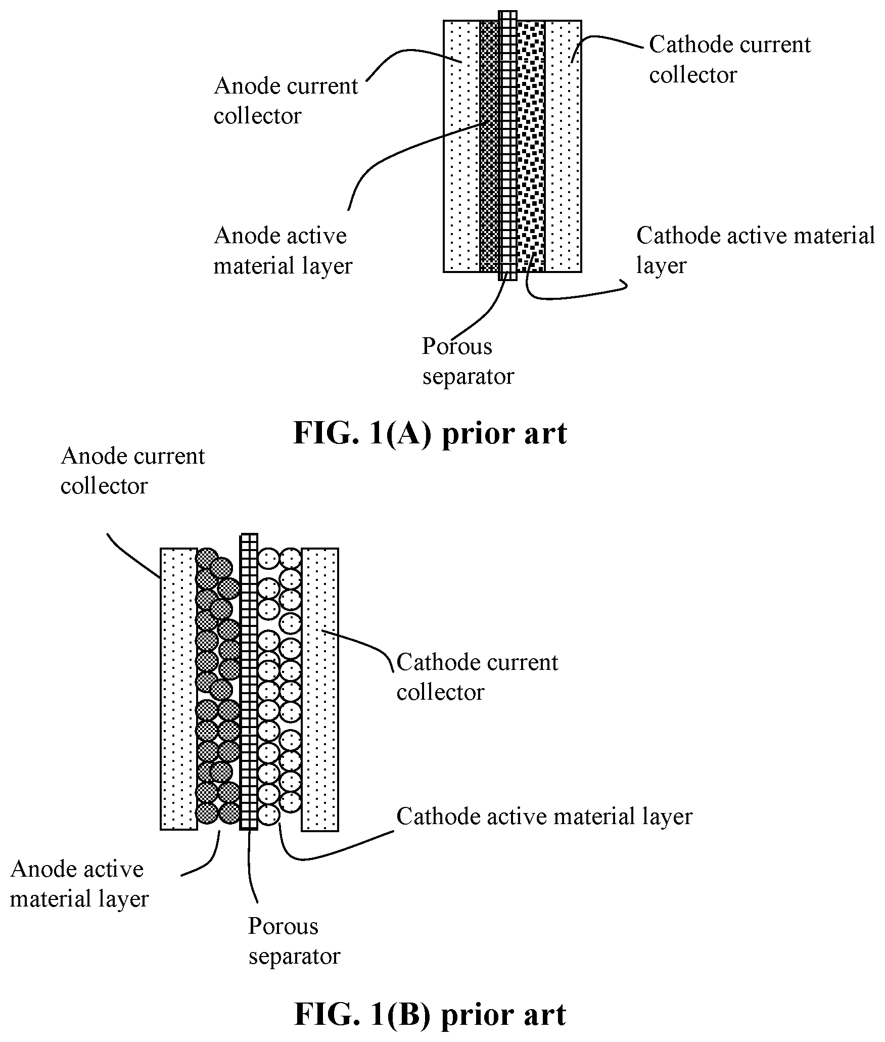
[0069] FIG. 1(A) Schematic of a prior art alkali metal-sulfur battery cell;
[0070] FIG. 1(B) Schematic of another prior art alkali metal-sulfur battery cell;
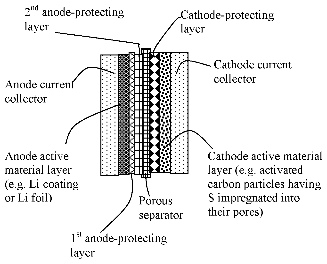
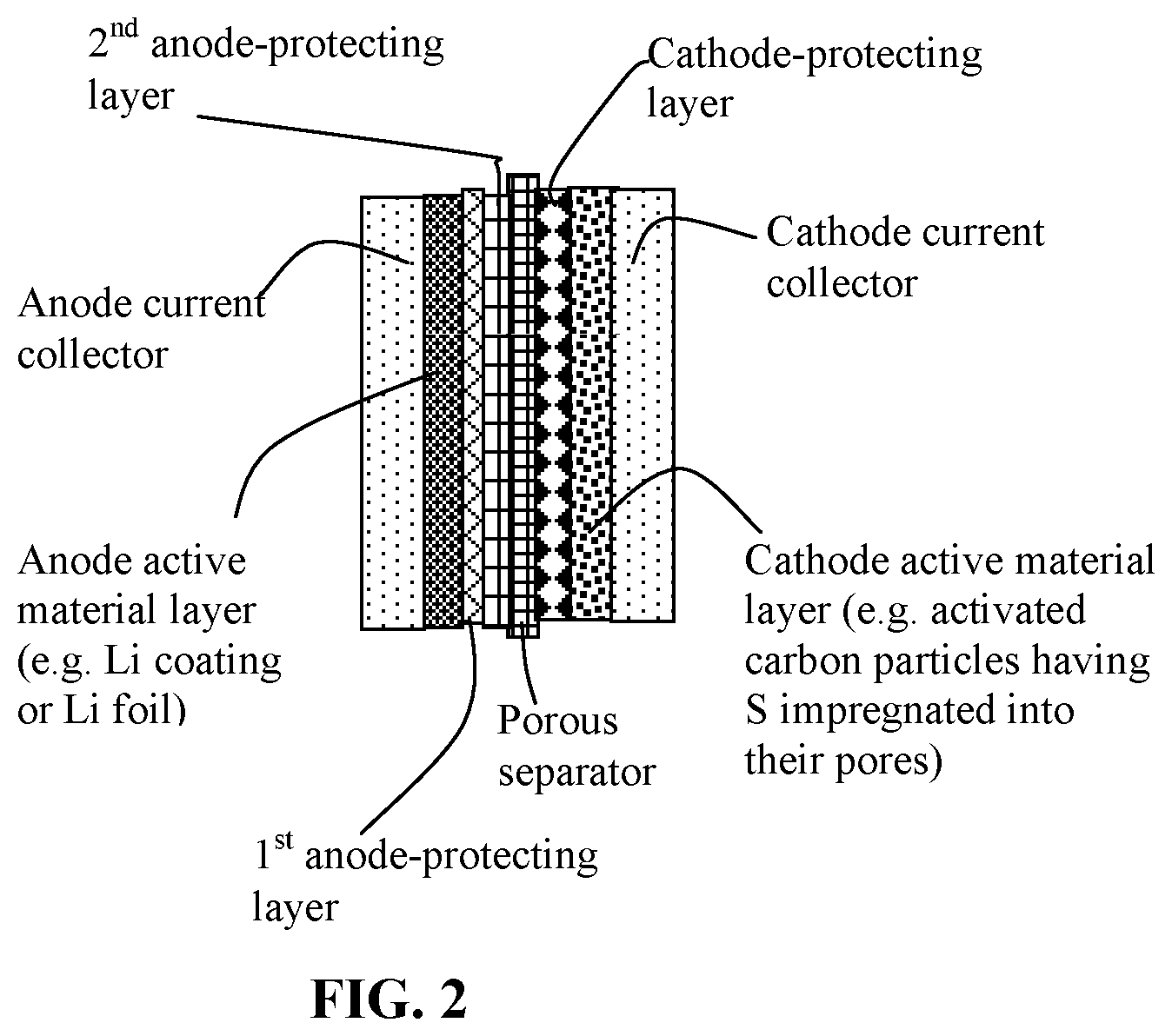
[0071] FIG. 2 Schematic of the presently invented alkali metal-sulfur cell containing two anode-protecting layers and a cathode-protecting layer. Either or two anode protecting layers and, optionally, one or two cathode-protecting layers may be included in a lithium-sulfur cell, Na--S cell, or K--S cell.
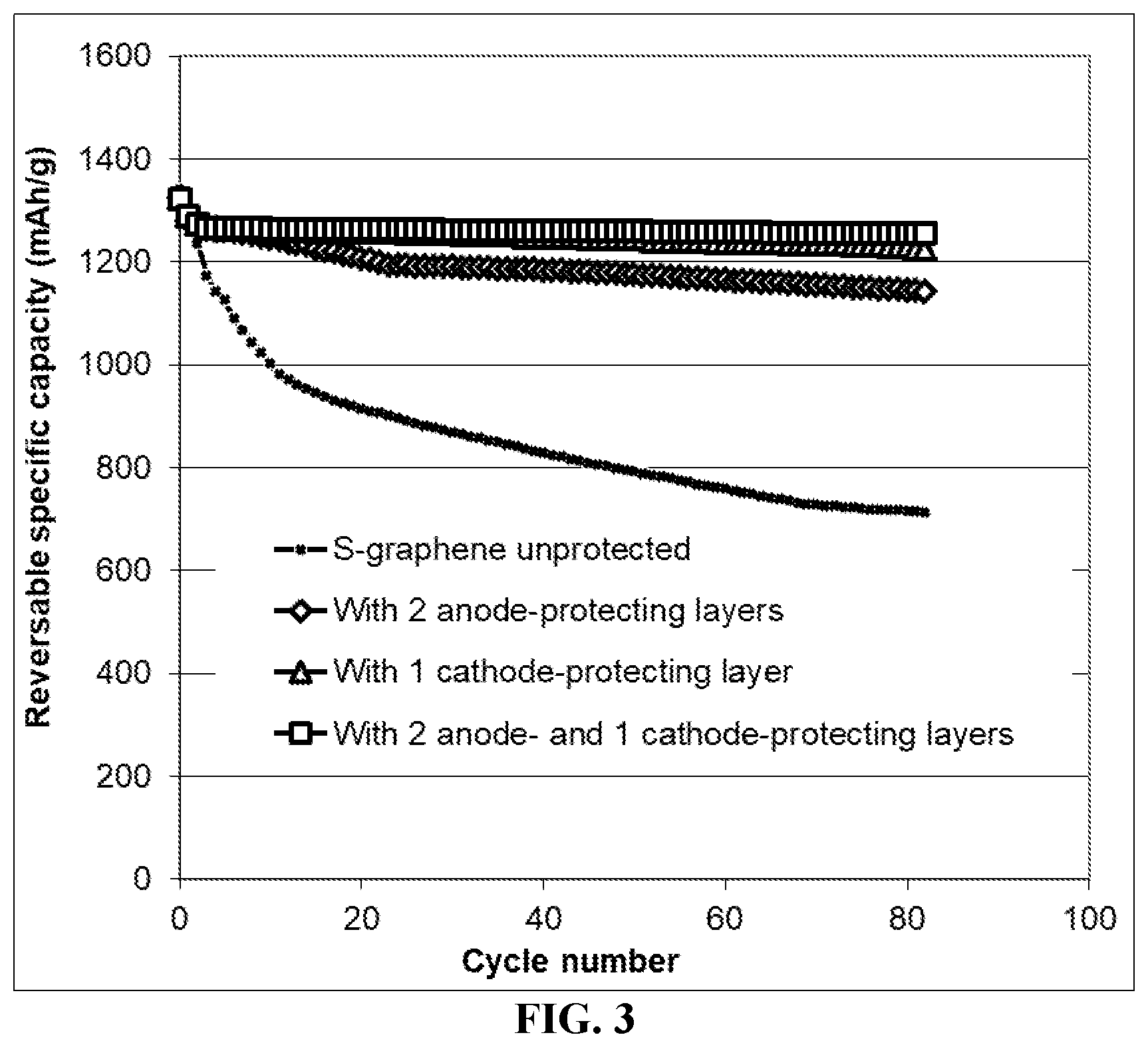
[0072] FIG. 3 The cycling behaviors of 4 cells, each having a Li foil anode and a cathode containing graphene-supported sulfur particles as the cathode active material: one without any protecting layer, one with two anode-protecting layers but no cathode-protecting layer, one with a cathode-protecting layer but no anode-protecting layer, and one with two anode-protecting layers and one cathode-protecting layer.
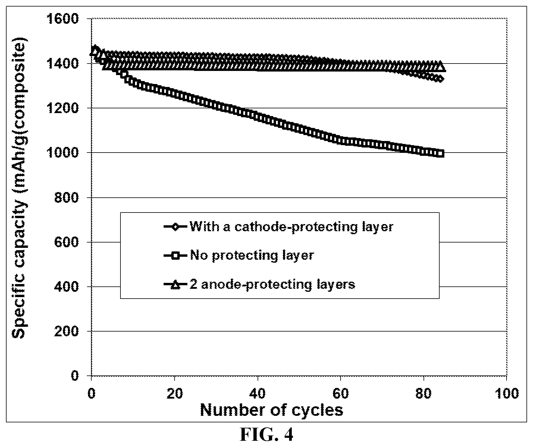
[0073] FIG. 4 The cathode specific capacity values of 3 Li--S cells; the first cell has a cathode-protecting layer containing a sulfonated SBS (no anode-protecting layer), the second layer contains 2 anode-protecting layers (no cathode-protecting layer), and the third cell has no cathode-protecting layer.
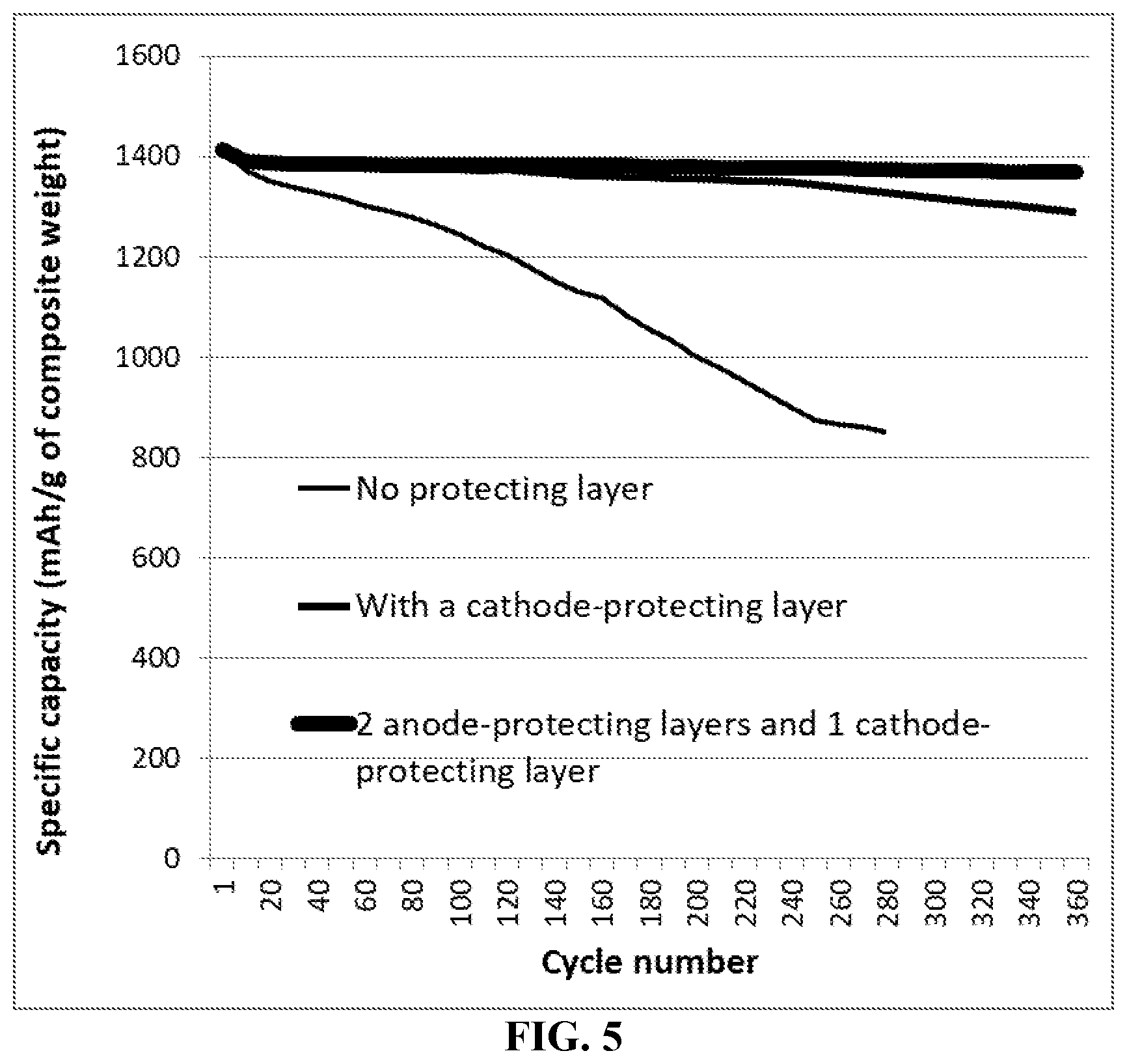
[0074] FIG. 5 The cathode specific capacity values of three room temperature Na--S cells each featuring a cathode active material layer containing sulfur-MCMB (activated) composite particles as the cathode active material: first cell has a SIBS/RGO composite-based cathode-protecting protecting layer, second cell has 2 anode-protecting layers and 1 cathode protecting layer (SIBS/RGO), and the third cell has t no protecting layer.
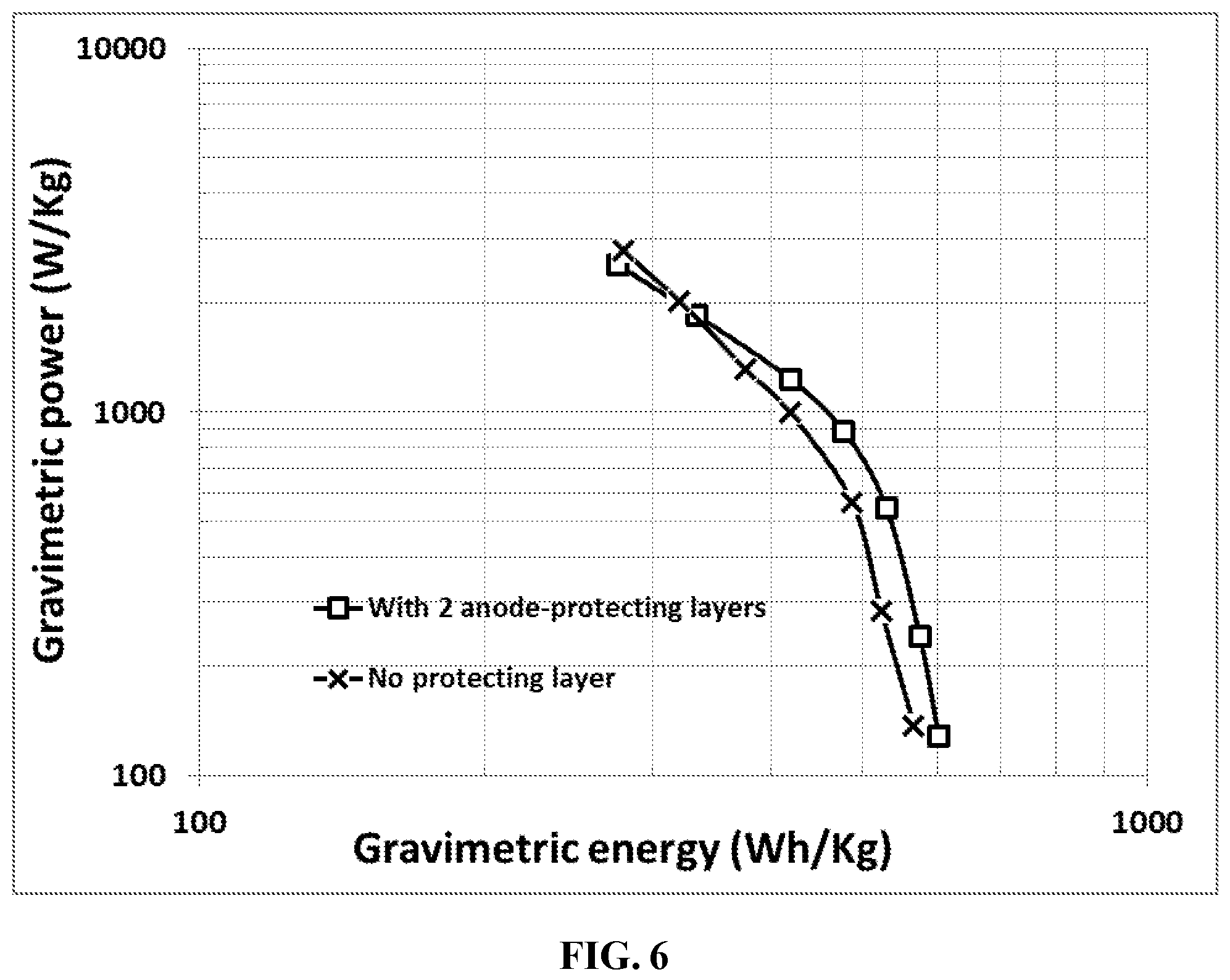
[0075] FIG. 6 Ragone plots (cell power density vs. cell energy density) of two Li metal-sulfur cells: one featuring two anode-protecting layers and the other without a protecting layer. The cathode active material is reduced graphene oxide-embraced S particles.
[0076] FIG. 7 Ragone plots (cell power density vs. cell energy density) of 4 alkali metal-sulfur cells each having a cathode active material layer containing particles of exfoliated graphite worms electrochemically impregnated with sulfur as the cathode active material: one Na--S cell featuring two anode-protecting layers, one Na--S cell without a protecting layer, one K--S cell featuring two anode-protecting layers, and 1 K--S cell without a protecting layer.
DETAILED DESCRIPTION OF PREFERRED EMBODIMENTS
[0077] For convenience, the following discussion of preferred embodiments is primarily based on Li--S cells, but the same or similar composition, structure, and methods are applicable to Na--S and K--S cells. Examples are presented for Li--S cells, room-temperature Na--S cells, and K--S cells. Conventional Li--S cells are illustrated in FIG. 1(A) and FIG. 1(B).
A. Alkali Metal-Sulfur Cells (Using Lithium-Sulfur Cells as an Example)
[0078] The specific capacity and specific energy of a Li--S cell (or Na--S, or K--S cell) are dictated by the actual amount of sulfur that can be implemented in the cathode active layer (relative to other non-active ingredients, such as the binder resin and conductive filler) and the utilization rate of this sulfur amount (i.e. the utilization efficiency of the cathode active material or the actual proportion of S that actively participates in storing and releasing lithium ions). Using Li--S cell as an illustrative example, a high-capacity and high-energy Li--S cell requires a high amount of S in the cathode active layer (i.e. relative to the amounts of non-active materials, such as the binder resin, conductive additive, and other modifying or supporting materials) and a high S utilization efficiency). The present invention provides such a cathode active layer, its constituent powder mass product, the resulting Li--S cell, and a method of producing such a cathode active layer and battery.
[0079] In some embodiments, as illustrated in FIG. 2, the alkali metal-sulfur cell (selected from lithium-sulfur cell, sodium-sulfur cell, or potassium-sulfur cell, said alkali metal-sulfur cell) comprises: (a) an anode; (b) a cathode active material layer, comprising a sulfur-containing material selected from a sulfur-carbon hybrid, sulfur-graphite hybrid, sulfur-graphene hybrid, conducting polymer-sulfur hybrid, metal sulfide, sulfur compound, or a combination thereof, and an optional cathode current collector supporting said cathode active material layer; and (c) an electrolyte or electrolyte/separator layer; wherein the anode comprises: (i) an anode active material layer containing a layer of lithium or lithium alloy, in a form of a foil, coating, or multiple particles aggregated together, as an anode active material and an optional anode current collector supporting the anode active material layer; (ii) a first anode-protecting layer having a thickness from 1 nm to 100 .mu.m and comprising a thin layer of electron-conducting material selected from graphene sheets, carbon nanotubes, carbon nanofibers, carbon or graphite fibers, expanded graphite flakes, metal nanowires, conductive polymer fibers, or a combination thereof, wherein the first anode-protecting layer has a specific surface area greater than 50 m.sup.2/g and is in physical contact with the anode active material layer; and (iii) a second anode-protecting layer in physical contact with the first anode-protecting layer, having a thickness from 1 nm to 100 .mu.m and comprising an elastomer having a fully recoverable tensile elastic strain from 2% to 1,000% and a lithium ion conductivity from 10.sup.-8 S/cm to 5.times.10.sup.-2 S/cm when measure at room temperature.
[0080] Preferably, the elastomer layer has a lithium ion conductivity no less than 10.sup.-6 S/cm (typically from 10.sup.-5 S/cm to 5.times.10.sup.-2 S/cm, measured at room temperature), and a thickness from 10 nm to 20 .mu.m. In some embodiments, the elastomer has from 0.01% to 40% by weight of an additive dispersed therein.
[0081] The first anode-protecting layer, being electron-conducting and having a high specific surface area (preferably >50 m.sup.2/g) can significantly decrease the exchange current density imposed on the anode active material (the Li metal), to the extent that presumably the local exchange current density can be lower than the threshold exchange current density for lithium dendrite initiation or that for the dendrite propagation, once initiated.
[0082] Preferably, the first anode-protecting layer contains a thin membrane, paper, non-woven, woven fabric, etc. of graphene sheets, carbon nanotubes, carbon nanofibers, carbon or graphite fibers, expanded graphite flakes, metal nanowires, conductive polymer fibers, or a combination thereof. This layer must be reasonably permeable to lithium ions; e.g. having pores to allow for easy migration of lithium ions.
[0083] The graphene sheets to be used in the 1.sup.st anode-protecting layer or to be dispersed in an elastomer matrix are preferably selected from pristine graphene, graphene oxide, reduced graphene oxide, graphene fluoride, graphene chloride, nitrogenated graphene, hydrogenated graphene, doped graphene, functionalized graphene, or a combination thereof. The graphene sheets preferably comprise single-layer graphene or few-layer graphene, wherein the few-layer graphene is defined as a graphene platelet formed of less than 10 graphene planes. The carbon nanotubes (CNTs) can be a single-walled CNT or multi-walled CNT. The carbon nanofibers may be vapor-grown carbon nanofibers or electrospinning based carbon nanofibers (e.g. electrospun polymer nanofibers that are subsequently carbonized).
[0084] Preferably, the elastomer in the 2.sup.nd anode-protecting layer contains a sulfonated or non-sulfonated version of an elastomer selected from natural polyisoprene, synthetic polyisoprene, polybutadiene, chloroprene rubber, polychloroprene, butyl rubber, styrene-butadiene rubber, nitrile rubber, ethylene propylene rubber, ethylene propylene diene rubber, metalloceite-based poly(ethylene-co-octene) (POE) elastomer, poly(ethylene-eo-butene) (PBE) elastomer, styrene-ethylene-butadiene-styrene (SEBS) elastomer, epichlorohydrin rubber, polyacrylic rubber, silicone rubber, fluorosilicone rubber, perfluoroelastomers, polyether block amides, chlorosulfonated polyethylene, ethylene-vinyl acetate, thermoplastic elastomer, protein resilin, protein elastin, ethylene oxide-epichlorohydrin copolymer, polyurethane, urethane-urea copolymer, or a combination thereof.
[0085] The sulfur-carbon hybrid, sulfur-graphite hybrid, sulfur-graphene hybrid, or conducting polymer-sulfur hybrid may be a mixture, blend, composite, or chemically or physically bonded entity of sulfur or sulfide with a carbon, graphite, graphene, or conducting polymer material. For instance, a sulfur-graphene hybrid can be a simple mixture (in a particle form) of sulfur and graphene prepared by ball-milling. Such a hybrid can contain sulfur bonded on surfaces of a graphene oxide sheet, etc. As another example, the sulfur-carbon hybrid can be a simple mixture (in a particle form) of sulfur and carbon nanotubes, or can contain sulfur residing in pores of activated carbon particles. In the instant cathode layer, these particles of sulfur hybrid are embraced by a sulfonated elastomer composite.
[0086] In the rechargeable alkali metal-sulfur cell, the metal sulfide may contain a material denoted by M,S.sub.y, wherein x is an integer from 1 to 3 and y is an integer from 1 to 10, and M is a metal element selected from an alkali metal, an alkaline metal selected from Mg or Ca, a transition metal, a metal from groups 13 to 17 of the periodic table, or a combination thereof. The metal element M preferably is selected from Li, Na, K, Mg, Zn, Cu, Ti, Ni, Co, Fe, or Al. In some preferred embodiments, the metal sulfide in the cathode layer contains Li.sub.2S.sub.1, Li.sub.2S.sub.2, Li.sub.2S.sub.3, Li.sub.2S.sub.4, Li.sub.2S.sub.5, Li.sub.2S.sub.6, Li.sub.2S.sub.7, Li.sub.2S.sub.8, Li.sub.2S.sub.9, Li.sub.2S.sub.10, Na.sub.2S.sub.1, Na.sub.2S.sub.2, Na.sub.2S.sub.3, Na.sub.2S.sub.4, Na.sub.2S.sub.5, Na.sub.2S.sub.6, Na.sub.2S.sub.7, Na.sub.2S.sub.8, Na.sub.2S.sub.9, Na.sub.2S.sub.10, K.sub.2S.sub.1, K.sub.2S.sub.2, K.sub.2S.sub.3, K.sub.2S.sub.4, K.sub.2S.sub.5, K.sub.2S.sub.6, K.sub.2S.sub.7, K.sub.2S.sub.8, K.sub.2S.sub.9, or K.sub.2S.sub.10.
[0087] In the rechargeable alkali metal-sulfur cell, the carbon or graphite material in the cathode active material layer may be selected from mesophase pitch, mesophase carbon, mesocarbon microbead (MCMB), coke particle, expanded graphite flake, artificial graphite particle, natural graphite particle, highly oriented pyrolytic graphite, soft carbon particle, hard carbon particle, carbon nanotube, carbon nanofiber, carbon fiber, graphite nanofiber, graphite fiber, carbonized polymer fiber, activated carbon, carbon black, or a combination thereof. The graphene may be selected from pristine graphene, graphene oxide, reduced graphene oxide (RGO), graphene fluoride, nitrogenated graphene, hydrogenated graphene, doped graphene, functionalized graphene, or a combination thereof.
[0088] The conducting polymer-sulfur hybrid may preferably contain an intrinsically conductive polymer selected from polyaniline, polypyrrole, polythiophene, polyfuran, a bi-cyclic polymer, a sulfonated derivative thereof, or a combination thereof. This can be a simple mixture of sulfur or metal sulfide with a conducting polymer.
[0089] In certain embodiments, the elastomer contains from 0.1% to 40% by weight of a lithium ion-, sodium ion-, or potassium ion-conducting additive dispersed therein. The lithium ion-conducting additive, along with an optional conductive reinforcement material, is dispersed in the sulfonated elastomer matrix and is selected from Li.sub.2CO.sub.3, Li.sub.2O, Li.sub.2C.sub.2O.sub.4, LiOH, LiX, ROCO.sub.2Li, HCOLi, ROLi, (ROCO.sub.2Li).sub.2, (CH.sub.2OCO.sub.2Li).sub.2, Li.sub.2S, Li.sub.xSO.sub.y, or a combination thereof, wherein X.dbd.F, Cl, I, or Br, R=a hydrocarbon group, 0<x.ltoreq.1, 1.ltoreq.y.ltoreq.4.
[0090] The lithium ion-conducting additive may be selected from lithium perchlorate (LiClO.sub.4), lithium hexafluorophosphate (LiPF.sub.6), lithium borofluoride (LiBF.sub.4), lithium hexafluoroarsenide (LiAsF.sub.6), lithium trifluoro-methanesulfonate (LiCF.sub.3SO.sub.3), bis-trifluoromethyl sulfonylimide lithium (LiN(CF.sub.3SO.sub.2).sub.2), lithium bis(oxalato)borate (LiBOB), lithium oxalyldifluoroborate (LiBF.sub.2C.sub.2O.sub.4), lithium nitrate (LiNO.sub.3), Li-fluoroalkyl-phosphate (LiPF.sub.3(CF.sub.2CF.sub.3).sub.3), lithium bisperfluoro-ethylsulfonylimide (LiBETI), lithium bis(trifluoromethanesulfonyl)imide, lithium bis(fluorosulfonyl)imide, lithium trifluoromethanesulfonimide (LiTFSI), an ionic liquid-based lithium salt, or a combination thereof. The sodium ion- or potassium ion-conducting additive, dispersed in the UHMW polymer, may be selected from sodium perchlorate (NaClO.sub.4), potassium perchlorate (KClO.sub.4), sodium hexafluorophosphate (NaPF.sub.6), potassium hexafluorophosphate (KPF.sub.6), sodium borofluoride (NaBF.sub.4), potassium borofluoride (KBF.sub.4), sodium hexafluoroarsenide, potassium hexafluoroarsenide, sodium trifluoro-methanesulfonate (NaCF.sub.3SO.sub.3), potassium trifluoro-methanesulfonate (KCF.sub.3SO.sub.3), bis-trifluoromethyl sulfonylimide sodium (NaN(CF.sub.3SO.sub.2).sub.2), sodium trifluoromethanesulfonimide (NaTFSI), bis-trifluoromethyl sulfonylimide potassium (KN(CF.sub.3SO.sub.2).sub.2), or a combination thereof.
[0091] An elastomer is a high-elasticity material, which exhibits an elastic deformation that is from at least 2% to 1,000% when measured under uniaxial tension (without an additive or reinforcement in the polymer, but can contain a lithium salt and/or liquid solvent dispersed in the polymer). In the field of materials science and engineering, the "elastic deformation" is defined as a deformation of a material (when being mechanically stressed) that is essentially fully recoverable and the recovery is essentially instantaneous upon release of the load. The elastic deformation of the sulfonated elastomer is preferably and typically greater than 5%, more preferably and typically greater than 10%, further more preferably and typically greater than 30%, still more preferably greater than 50%, and most preferably greater than 100%.
[0092] Not to be bound by theory, but the applicants believe that the anode-protecting layer is capable of performing at least the following three functions: [0093] 1) Being highly elastic, the elastomer layer helps to maintain a good contact between an alkali metal layer (e.g. lithium metal foil, as the anode active material) and an electrolyte phase (e.g. an electrolyte or electrolyte/separator assembly) when the alkali metal layer decreases in thickness (e.g. due to dissolution of Li in the electrolyte when the battery is discharged) or increases in thickness (e.g. due to re-deposition of lithium metal back to the Cu foil or lithium metal when the battery is recharged). The same function also works for the alkali metal-sulfur cell containing lithiated Si particles as an anode active material, as an example. Si particles and the entire anode active material layer can shrink and expand when the battery is discharged or charged. The elastomer can expand and shrink responsive to the shrinkage and expansion of the anode active material layer. Such a conformal or congruent expansion/shrinkage of the elastomer helps to eliminate the potential gap between the anode active material layer and the electrolyte or separator, thereby maintaining the lithium ion migration paths required of an operational Li--S battery. [0094] 2) The elastomer, infiltrated with a liquid electrolyte (before, during, or after the cell is fabricated) and coupled with its high-elasticity nature (good electrode-electrolyte contact), enables the returning alkali metal ions (e.g. Li.sup.+ or Na.sup.+ ions) to uniformly and successfully deposit back to the alkali metal surface, reducing the formation of dead lithium particles (or dead sodium particles), which otherwise become inactive. The uniform deposition of alkali metal also reduces the tendency to form the dangerous Li or Na dendrite. [0095] 3) The presence of the conductive reinforcement material (graphene sheets, CNTs, CNFs, etc.) are high strength materials, capable of stopping or deflecting the growth of dendrites (if initiated), preventing the dendrite from penetrating the separator and reaching the cathode side to induce internal shorting, which otherwise is a fire and explosion hazard.
[0096] In certain embodiments, the alkali metal-sulfur cell may further comprise one or two cathode protecting layers disposed between the cathode active layer and the separator/electrolyte layer: [0097] a) a first cathode-protecting layer having a thickness from 1 nm to 100 .mu.m and comprising a thin layer of electron-conducting material selected from graphene sheets, carbon nanotubes, carbon nanofibers, carbon or graphite fibers, expanded graphite flakes, metal nanowires, conductive polymer fibers, or a combination thereof, wherein said first anode-protecting layer has a specific surface area greater than 50 m.sup.2/g and is in physical contact with the cathode active material layer or the separator/electrolyte layer; and/or [0098] b) a second cathode-protecting layer in physical contact with the first cathode-protecting layer, having a thickness from 1 nm to 100 .mu.m and comprising an elastomer having a fully recoverable tensile elastic strain from 2% to 1,000% and a lithium ion conductivity from 10.sup.-8 S/cm to 5.times.10.sup.-2 S/cm when measure at room temperature.
[0099] The 1.sup.st cathode-protecting layer may be the same as or different than the 1.sup.st anode-protecting layer. The 2.sup.nd cathode-protecting layer may be the same as or different than the 2.sup.nd cathode-protecting layer.
[0100] Not to be bound by theory, but the applicants further believe that the cathode-protecting layer is capable of performing at least the following two functions: [0101] 1) Sulfur and lithium polysulfide, and the entire cathode active material layer, can expand and shrink when the battery is discharged or charged. The elastomer layer implemented between the cathode active material layer and the separator layer (or the electrolyte phase) can shrink and expand responsive to the expansion and shrinkage of the cathode active material layer. Such a conformal or congruent expansion/shrinkage of the sulfonated elastomer composite helps to eliminate the potential gap between the cathode active material layer and the electrolyte or separator, thereby maintaining the lithium ion migration paths required of an operational Li--S battery. [0102] 2) The conductive material-based layer also acts to trap and block the sulfur or metal polysulfide species dissolved in the electrolyte, thereby preventing continuing migration of these species to the anode side where they react with lithium (or sodium, or potassium) and are unable to return to the cathode (the shuttle effect). This shuttle effect is mainly responsible for continued and rapid capacity decay in a conventional Li--S, room-temperature Na--S, or K--S cell.
[0103] Alternatively, referring to the lower portion of FIG. 3, lithium sulfide is used as the cathode active material. A layer of elastomer may encapsulate around the lithium polysulfide particle to form a core-shell structure. When the Li--S battery is charged and lithium ions are released from the cathode, the cathode active material particle contracts. However, the elastomer is capable of elastically shrinking in a conformal manner; hence, leaving behind no gap between the protective shell and the sulfur. Such a configuration is amenable to subsequent lithium reaction with sulfur. The elastomer shell expands and shrinks congruently with the expansion and shrinkage of the encapsulated core cathode active material particle, enabling long-term cycling stability of a Li--S or Na--S battery.
B. Sulfonated or Un-Sulfonated Elastomer or Elastomer Composites
[0104] Preferably and typically, the elastomer layer has a lithium ion conductivity no less than 10.sup.-6 S/cm, more preferably no less than 10.sup.-4 S/cm, further preferably no less than 10.sup.-3 S/cm, and most preferably no less than 10.sup.-2 S/cm. In some embodiments, the elastomer layer contains no additive or filler dispersed therein. In others, the elastomer contains from 0.1% to 50% (preferably 1% to 35%) by weight of a lithium ion-conducting additive dispersed in an elastomer matrix material. The elastomer must have a high elasticity (elastic deformation strain value >2%). An elastic deformation is a deformation that is fully recoverable and the recovery process is essentially instantaneous (no significant time delay). The sulfonated elastomer composite can exhibit an elastic deformation from 5% up to 800% (8 times of its original length), more typically from 10% to 500%, and further more typically from 30% to 300%.
[0105] It may be noted that although a metal or a plastic typically has a high ductility (i.e. can be extended to a large strain without breakage), the majority of the deformation is plastic deformation (non-recoverable) and only a small amount of elastic deformation (typically <1% and more typically <0.2%). Thus, a metal or a plastic does not qualify as a high-elasticity material.
[0106] Further, we have unexpectedly discovered that the presence of an amount of a lithium salt or sodium salt (1-35% by weight) and a liquid solvent (0-50%) can significantly increase the lithium-ion or sodium ion conductivity of the sulfonated elastomer matrix.
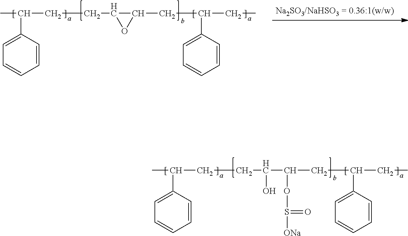
[0107] The first step for producing an elastomer layer is to dissolve an elastomer or its precursor (e.g. uncured oligomer or polymer) in a solvent to form a polymer solution. Subsequently, the conductive reinforcement material and other additive are dispersed in this polymer solution to form a suspension (dispersion or slurry). This suspension can then be subjected to a film-forming procedure (e.g. spraying, printing, casting, coating, etc.) and a solvent removal treatment. The elastomer precursor is then cured or polymerized.
[0108] One may dispense and deposit a layer of a first elastomer onto a primary surface of a protected anode active material layer. Alternatively, one may dispense and deposit a layer of a first elastomer onto a primary surface of a separator layer. Further alternatively, one may prepare separate free-standing discrete layers of the elastomer and other components first. One or both of these layers are then laminated together with the anode layer, separator/electrolyte, and the cathode layer to form a battery cell.
[0109] The procedures of spraying, printing, casting, coating, and laminating are well-known in the art.
[0110] The elastomer may form a mixture or blend with an electron-conducting polymer selected from polyaniline, polypyrrole, polythiophene, polyfuran, a bi-cyclic polymer, derivatives thereof (e.g. sulfonated versions), or a combination thereof.
[0111] In some embodiments, the elastomer may form a mixture with a lithium ion-conducting polymer selected from regular molecular weight (<500,000 g/mole) version of poly(ethylene oxide) (PEO), polypropylene oxide (PPO), poly(acrylonitrile) (PAN), poly(methyl methacrylate) (PMMA), poly(vinylidene fluoride) (PVDF), poly bis-methoxy ethoxyethoxide-phosphazene, polyvinyl chloride, polydimethylsiloxane, poly(vinylidene fluoride)-hexafluoropropylene (PVDF-HFP), a derivative thereof (e.g. sulfonated versions), or a combination thereof.
[0112] A wide variety of rubbers or elastomers may be readily sulfonated using known sulfonation procedures. Unsaturated rubbers that can be vulcanized to become elastomer include natural polyisoprene (e.g. cis-1,4-polyisoprene natural rubber (NR) and trans-1,4-polyisoprene gutta-percha), synthetic polyisoprene (IR for isoprene rubber), polybutadiene (BR for butadiene rubber), chloroprene rubber (CR), polychloroprene (e.g. Neoprene, Baypren etc.), butyl rubber (copolymer of isobutylene and isoprene, IIR), including halogenated butyl rubbers (chloro butyl rubber (CIIR) and bromo butyl rubber (BIIR), styrene-butadiene rubber (copolymer of styrene and butadiene, SBR), nitrile rubber (copolymer of butadiene and acrylonitrile, NBR),
[0113] Some elastomers are saturated rubbers that cannot be cured by sulfur vulcanization; they are made into a rubbery or elastomeric material via different means: e.g. by having a copolymer domain that holds other linear chains together. Each of these elastomers can be used to encapsulate particles of an anode active material by one of several means: melt mixing (followed by pelletizing and ball-milling, for instance), solution mixing (dissolving the anode active material particles in an uncured polymer, monomer, or oligomer, with or without an organic solvent) followed by drying (e.g. spray drying), interfacial polymerization, or in situ polymerization of elastomer in the presence of anode active material particles.
[0114] Sulfonated saturated rubbers and related elastomers in this category include EPM (ethylene propylene rubber, a copolymer of ethylene and propylene), EPDM rubber (ethylene propylene diene rubber, a terpolymer of ethylene, propylene and a diene-component), epichlorohydrin rubber (ECO), polyacrylic rubber (ACM, ABR), silicone rubber (SI, Q, VMQ), fluorosilicone rubber (FVMQ), fluoroelastomers (FKM, and FEPM; such as Viton, Tecnoflon, Fluorel, Aflas and Dai-El), perfluoroelastomers (FFKM: Tecnoflon PFR, Kalrez, Chemraz, Perlast), polyether block amides (PEBA), chlorosulfonated polyethylene (CSM; e.g. Hypalon), and ethylene-vinyl acetate (EVA), thermoplastic elastomers (TPE), protein resilin, and protein elastin. Sulfonated polyurethane and its copolymers (e.g. urea-urethane copolymer) are particularly useful elastomeric shell materials for encapsulating anode active material particles.
[0115] A variety of synthetic methods may be used to sulfonate an elastomer or rubber: (i) exposure to sulfur trioxide in vapor phase or in solution, possibly in presence of Lewis bases such as triethyl phosphate, tetrahydrofuran, dioxane, or amines; (ii) chlorosulfonic acid in diethyl ether; (iii) concentrated sulfuric acid or mixtures of sulfuric acid with alkyl hypochlorite; (iv) bisulfites combined to dioxygen, hydrogen peroxide, metallic catalysts, or peroxo derivates; and (v) acetyl sulfate.
[0116] Sulfonation of an elastomer or rubber may be conducted before, during, or after curing of the elastomer or rubber. Further, sulfonation of the elastomer or rubber may be conducted before or after the particles of an electrode active material are embraced or encapsulated by the elastomer/rubber or its precursor (monomer or oligomer). Sulfonation of an elastomer or rubber may be accomplished by exposing the elastomer/rubber to a sulfonation agent in a solution state or melt state, in a batch manner or in a continuous process. The sulfonating agent may be selected from sulfuric acid, sulfonic acid, sulfur trioxide, chlorosulfonic acid, a bisulfate, a sulfate (e.g. zinc sulfate, acetyl sulfate, etc.), a mixture thereof, or a mixture thereof with another chemical species (e.g. acetic anhydride, thiolacetic acid, or other types of acids, etc.). In addition to zinc sulfate, there are a wide variety of metal sulfates that may be used as a sulfonating agent; e.g. those sulfates containing Mg, Ca, Co, Li, Ba, Na, Pb, Ni, Fe, Mn, K, Hg, Cr, and other transition metals, etc.
[0117] For instance, a triblock copolymer, poly(styrene-isobutylene-styrene) or SIBS, may be sulfonated to several different levels ranging from 0.36 to 2.04 mequiv./g (13 to 82 mol % of styrene; styrene being 19 mol % of the unsulfonated block copolymer). Sulfonation of SIBS may be performed in solution with acetyl sulfate as the sulfonating agent. First, acetic anhydride reacts with sulfuric acid to form acetyl sulfate (a sulfonating agent) and acetic acid (a by-product). Then, excess water is removed since anhydrous conditions are required for sulfonation of SIBS. The SIBS is then mixed with the mixture of acetyl sulfate and acetic acid. Such a sulfonation reaction produces sulfonic acid substituted to the para-position of the aromatic ring in the styrene block of the polymer. Elastomers having an aromatic ring may be sulfonated in a similar manner.
[0118] A sulfonated elastomer also may be synthesized by copolymerization of a low level of functionalized (i.e. sulfonated) monomer with an unsaturated monomer (e.g. olefinic monomer, isoprene monomer or oligomer, butadiene monomer or oligomer, etc.).
C. Additional Details About the Structure of Li--S, Na--S, and K--S Cells
[0119] The anode active material layer of an alkali metal-sulfur cell can contain a foil or coating of Li, Na, or K supported by a current collector (e.g. Cu foil), as illustrated in the left-hand portion of FIG. 1(A) for a prior art Li--S cell. Alternatively, the anode active material may contain, for instance, particles of prelithiated Si particles or surface-stabilized Li particles, as illustrated in FIG. 2. However, the cathode layer in the instant cell is distinct, as already discussed above.
[0120] The electrolyte for an alkali metal-sulfur cell may be an organic electrolyte, ionic liquid electrolyte, gel polymer electrolyte, solid-state electrolyte (e.g. polymer solid electrolyte or inorganic solid electrolyte), quasi-solid electrolyte or a combination thereof. The electrolyte typically contains an alkali metal salt (lithium salt, sodium salt, and/or potassium salt) dissolved in a solvent.
[0121] The solvent may be selected from 1,3-dioxolane (DOL), 1,2-dimethoxyethane (DME), tetraethylene glycol dimethylether (TEGDME), poly(ethylene glycol) dimethyl ether (PEGDME), diethylene glycol dibutyl ether (DEGDBE), 2-ethoxyethyl ether (EEE), sulfone, sulfolane, ethylene carbonate (EC), dimethyl carbonate (DMC), methylethyl carbonate (MEC), diethyl carbonate (DEC), ethyl propionate, methyl propionate, propylene carbonate (PC), gamma-butyrolactone (.gamma.-BL), acetonitrile (AN), ethyl acetate (EA), propyl formate (PF), methyl formate (MF), toluene, xylene, methyl acetate (MA), fluoroethylene carbonate (FEC), vinylene carbonate (VC), allyl ethyl carbonate (AEC), a hydrofluoroether, a room temperature ionic liquid solvent, or a combination thereof.
[0122] The electrolytic salts to be incorporated into a non-aqueous electrolyte may be selected from a lithium salt such as lithium perchlorate (LiClO.sub.4), lithium hexafluorophosphate (LiPF.sub.6), lithium borofluoride (LiBF.sub.4), lithium hexafluoroarsenide (LiAsF.sub.6), lithium trifluoro-methanesulfonate (LiCF.sub.3SO.sub.3), bis-trifluoromethyl sulfonylimide lithium [LiN(CF.sub.3SO.sub.2).sub.2], lithium bis(oxalato)borate (LiBOB), lithium oxalyldifluoroborate (LiBF.sub.2C.sub.2O.sub.4), lithium nitrate (LiNO.sub.3), Li-Fluoroalkyl-Phosphates (LiPF3(CF.sub.2CF.sub.3).sub.3), lithium bisperfluoroethysulfonylimide (LiBETI), an ionic liquid salt, sodium perchlorate (NaClO.sub.4), potassium perchlorate (KClO.sub.4), sodium hexafluorophosphate (NaPF.sub.6), potassium hexafluorophosphate (KPF.sub.6), sodium borofluoride (NaBF.sub.4), potassium borofluoride (KBF.sub.4), sodium hexafluoroarsenide, potassium hexafluoroarsenide, sodium trifluoro-methanesulfonate (NaCF.sub.3SO.sub.3), potassium trifluoro-methanesulfonate (KCF.sub.3SO.sub.3), bis-trifluoromethyl sulfonylimide sodium (NaN(CF.sub.3SO.sub.2).sub.2), sodium trifluoromethanesulfonimide (NaTFSI), and bis-trifluoromethyl sulfonylimide potassium (KN(CF.sub.3SO.sub.2).sub.2). Among them, LiPF.sub.6, LiBF.sub.4 and LiN(CF.sub.3SO.sub.2).sub.2 are preferred for Li--S cells, NaPF.sub.6 and LiBF.sub.4 for Na--S cells, and KBF.sub.4 for K--S cells. The content of aforementioned electrolytic salts in the non-aqueous solvent is preferably 0.5 to 3.0 M (mol/L) at the cathode side and 3.0 to >10 M at the anode side.
[0123] The ionic liquid is composed of ions only. Ionic liquids are low melting temperature salts that are in a molten or liquid state when above a desired temperature. For instance, a salt is considered as an ionic liquid if its melting point is below 100.degree. C. If the melting temperature is equal to or lower than room temperature (25.degree. C.), the salt is referred to as a room temperature ionic liquid (RTIL). The IL salts are characterized by weak interactions, due to the combination of a large cation and a charge-delocalized anion. This results in a low tendency to crystallize due to flexibility (anion) and asymmetry (cation).
[0124] A typical and well-known ionic liquid is formed by the combination of a 1-ethyl-3-methylimidazolium (EMI) cation and an N,N-bis(trifluoromethane)sulfonamide (TFSI) anion. This combination gives a fluid with an ionic conductivity comparable to many organic electrolyte solutions and a low decomposition propensity and low vapor pressure up to .about.300-400.degree. C. This implies a generally low volatility and non-flammability and, hence, a much safer electrolyte for batteries.
[0125] Ionic liquids are basically composed of organic ions that come in an essentially unlimited number of structural variations owing to the preparation ease of a large variety of their components. Thus, various kinds of salts can be used to design the ionic liquid that has the desired properties for a given application. These include, among others, imidazolium, pyrrolidinium and quaternary ammonium salts as cations and bis(trifluoromethanesulfonyl) imide, bis(fluorosulfonyl)imide, and hexafluorophosphate as anions. Based on their compositions, ionic liquids come in different classes that basically include aprotic, protic and zwitterionic types, each one suitable for a specific application.
[0126] Common cations of room temperature ionic liquids (RTILs) include, but not limited to, tetraalkylammonium, di-, tri-, and tetra-alkylimidazolium, alkylpyridinium, dialkyl-pyrrolidinium, dialkylpiperidinium, tetraalkylphosphonium, and trialkylsulfonium. Common anions of RTILs include, but not limited to, BF.sub.4.sup.-, B(CN).sub.4.sup.-, CH.sub.3BF.sub.3.sup.-, CH2CHBF.sub.3.sup.-, CF.sub.3BF.sub.3.sup.-, C.sub.2F.sub.5BF.sub.3.sup.-, n-C.sub.3F.sub.7BF.sub.3.sup.-, n-C.sub.4F.sub.9BF.sub.3.sup.-, PF.sub.6.sup.-, CF.sub.3CO.sub.2.sup.-, CF.sub.3SO.sub.3.sup.-, N(SO.sub.2CF.sub.3).sub.2.sup.-, N(COCF.sub.3)(SO.sub.2CF.sub.3).sup.-, N(SO.sub.2F).sub.2.sup.-, N(CN).sub.2.sup.-, C(CN).sub.3.sup.-, SCN.sup.-, SeCN.sup.-, CuCl.sub.2.sup.-, AlCl.sub.4.sup.-, F(HF).sub.2.3.sup.-, etc. Relatively speaking, the combination of imidazolium- or sulfonium-based cations and complex halide anions such as AlCl.sub.4.sup.-, BF.sub.4.sup.-, CF.sub.3CO.sub.2.sup.-, CF.sub.3SO.sub.3.sup.-, NTf.sub.2.sup.-, N(SO.sub.2F).sub.2.sup.-, or F(HF).sub.2.3.sup.- results in RTILs with good working conductivities.
[0127] RTILs can possess archetypical properties such as high intrinsic ionic conductivity, high thermal stability, low volatility, low (practically zero) vapor pressure, non-flammability, the ability to remain liquid at a wide range of temperatures above and below room temperature, high polarity, high viscosity, and wide electrochemical windows. These properties, except for the high viscosity, are desirable attributes when it comes to using an RTIL as an electrolyte ingredient (a salt and/or a solvent) in a Li--S cell.
[0128] In the presently invented alkali metal-sulfur cell, the cathode active layer comprises sulfur or a sulfur-containing compound preferably supported by or embedded in a conducting material, forming a sulfur-carbon hybrid, sulfur-graphite hybrid, sulfur-graphene hybrid, conducting polymer-sulfur hybrid, metal sulfide, sulfur compound, etc. These hybrid or compound materials are produced in the form of particles that contain a mixture, blend, composite, or bonded entity of sulfur or sulfide with a carbon, graphite, graphene, or conducting polymer material. Metal sulfides (e.g. lithium polysulfide, sodium polysulfide, etc.) and sulfur compounds are readily available in a fine particle form. Sulfur can be combined with a conducting material (carbon, graphite, graphene, and/or conducting polymer) to form a composite, mixture, or bonded entity (e.g. sulfur bonded on graphene oxide surface).
[0129] There are many well-known procedures that can be used to make the aforementioned sulfur-containing materials into particles. For instance, one may mix solid sulfur with a carbon or graphite material to form composite particles using ball-milling. The resulting particles are typically ellipsoidal or potato-like in shape having a size from 1 to 20 .mu.m. Also, one may infiltrate S or sulfide into the pores of porous carbon or graphite particles (e.g. activated carbon, mesoporous carbon, activated carbon fibers, etc.) using vapor phase infiltration, solution infiltration, chemical infiltration, or electrochemical infiltration. Alternatively, one may deposit sulfur onto surfaces of graphene sheets, CNTs, carbon nanofibers, etc. and then form these S-coated nanomaterials into a spherical or ellipsoidal shape using high-intensity ball-milling, spray-drying (of their suspensions), aerosol formation, etc. These particles are then encapsulated with a sulfonated elastomer composite using the micro-encapsulation processes discussed above.
[0130] The cathode in a conventional Li--S cell typically has less than 70% by weight of sulfur in a composite cathode composed of sulfur and the conductive additive/support. Even when the sulfur content in the prior art composite cathode reaches or exceeds 70% by weight, the specific capacity of the composite cathode is typically significantly lower than what is expected based on theoretical predictions. For instance, the theoretical specific capacity of sulfur is 1,675 mAh/g. A composite cathode composed of 70% sulfur (S) and 30% carbon black (CB), without any binder, should be capable of storing up to 1,675.times.70%=1,172 mAh/g. Unfortunately, the observed specific capacity is typically less than 75% or 879 mAh/g (often less than 50% or 586 mAh/g in this example) of what could be achieved. In other words, the active material (S) utilization rate is typically less than 75% (or even <50%). This has been a major issue in the art of Li--S cells and there has been no solution to this problem.
[0131] Thus, it is highly advantageous to obtain a high sulfur loading and yet, concurrently, maintaining an ultra-thin/small thickness/diameter of sulfur for significantly enhanced sulfur utilization efficiency, energy density and power density. For instance, one can deposit nanoscaled sulfur (1-5 nm thick) on graphene surfaces using chemical, electrochemical, or vapor deposition to form S-coated or S-bonded graphene sheets. These S-coated or S-bonded graphene sheets are then aggregated together using a tumbling mixing, ball-milling, or spraying procedure. These steps enable the preparation of S-conducting material hybrids that contain 85%-99% by weight sulfur, yet maintaining a coating thickness or particle diameter from 1 nm to 5 nm. This ultra-small dimension enables fast lithium diffusion and lithium-sulfur reactions, leading to high S utilization efficiency (hence, high energy density) even at high charge-discharge rates. Several procedures of producing such small S particles or coating are illustrated in examples of this specification.
[0132] Again, the shuttling effect is related to the tendency for sulfur or alkali metal polysulfide that forms at the cathode to get dissolved in the solvent and for the dissolved lithium polysulfide species to migrate from the cathode to the anode, where they irreversibly react with lithium to form species that prevent sulfide from returning back to the cathode during the subsequent discharge operation of the Li--S cell (the detrimental shuttling effect). It appears that by implementing a cathode-protecting layer of a sulfonated elastomer composite, we have significantly reduced and even eliminated the shuttling effect, resulting in an alkali metal battery that has an exceptionally long cycle-life. We have solved the most critical, long-standing problem of alkali metal-sulfur batteries.
[0133] In all versions of the above-discussed alkali metal-sulfur cells, the anode active material may contain, as an example, lithium metal foil (or powder) or a high-capacity Si, Sn, Al, or SnO.sub.2 capable of storing a great amount of lithium. The cathode active material may contain pure sulfur (if the anode active material contains lithium), lithium polysulfide, or any sulfur containing compound, molecule, or polymer. If the cathode active material includes lithium-containing species (e.g. lithium polysulfide) when the cell is made, the anode active material can be any material capable of storing a large amount of lithium (e.g. Si, Ge, Sn, Al, SnO.sub.2, etc.).
[0134] At the anode side, when lithium metal is used as the sole anode active material in a Li--S cell, there is concern about the formation of lithium dendrites, which could lead to internal shorting and thermal runaway. Herein, we have used two approaches, separately or in combination, to address this dendrite formation issue: one involving the use of a protecting layer containing a sulfonated elastomer composite discussed above and the other the use of a nanostructure composed of conductive nanofilaments as an extended anode current collector. For the latter, multiple conductive nanofilaments are processed to form an integrated aggregate structure, preferably in the form of a closely packed web, mat, or paper, characterized in that these filaments are intersected, overlapped, or somehow bonded (e.g., using a binder material) to one another to form a network of electron-conducting paths. The integrated structure has substantially interconnected pores to accommodate electrolyte. The nanofilament may be selected from, as examples, a carbon nanofiber (CNF), graphite nanofiber (GNF), carbon nanotube (CNT), metal nanowire (MNW), conductive nanofibers obtained by electrospinning, conductive electrospun composite nanofibers, nanoscaled graphene platelet (NGP), or a combination thereof. The nanofilaments may be bonded by a binder material selected from a polymer, coal tar pitch, petroleum pitch, mesophase pitch, coke, or a derivative thereof.
[0135] Nano fibers may be selected from the group consisting of an electrically conductive electrospun polymer fiber, electrospun polymer nanocomposite fiber comprising a conductive filler, nano carbon fiber obtained from carbonization of an electrospun polymer fiber, electrospun pitch fiber, and combinations thereof. For instance, a nanostructured electrode can be obtained by electrospinning of polyacrylonitrile (PAN) into polymer nanofibers, followed by carbonization of PAN. It may be noted that some of the pores in the structure, as carbonized, are greater than 100 nm and some smaller than 100 nm.
[0136] The presently invented protective layers may be incorporated in one of at least four broad classes of rechargeable alkali metal-sulfur cells (using Li as an example): [0137] (A)Lithium metal-sulfur with a conventional anode configuration: The cell contains an optional cathode current collector, a cathode layer, a separator/electrolyte, an anode, and an anode current collector. Potential dendrite formation may be overcome by using the invented anode-protecting layer. There can be a cathode-protecting layer. [0138] (B) Lithium metal-sulfur cell with a nanostructured anode configuration: The cell contains an optional cathode current collector, a cathode, a separator/electrolyte, an optional anode current collector, and a nanostructure to accommodate lithium metal that is deposited back to the anode during a charge or re-charge operation. This nanostructure (web, mat, or paper) of nanofilaments provide a uniform electric field enabling uniform Li metal deposition, reducing the propensity to form dendrites. This configuration can provide a dendrite-free cell for a long and safe cycling behavior. Additionally, there can be an anode-protecting layer and/or a cathode-protecting layer. [0139] (C) Lithium ion-sulfur cell with a conventional anode: For instance, the cell contains an anode composed of anode active graphite particles bonded by a binder, such as polyvinylidene fluoride (PVDF) or styrene-butadiene rubber (SBR). The cell also contains a cathode current collector, a cathode, a separator/electrolyte, and an anode current collector. There can be an anode-protecting layer and/or a cathode-protecting layer; and [0140] (D) Lithium ion-sulfur cell with a nanostructured anode: For instance, the cell contains a web of nanofibers coated with Si coating or bonded with Si nanoparticles. The cell also contains an optional cathode current collector, a cathode, a separator/electrolyte, and an anode current collector. There can be an anode-protecting layer and/or a cathode-protecting layer. This configuration provides an ultra-high capacity, high energy density, and a safe and long cycle life.
[0141] In the lithium-ion sulfur cell (e.g. as described in (C) and (D) above), the anode active material can be selected from a wide range of high-capacity materials, including (a) silicon (Si), germanium (Ge), tin (Sn), lead (Pb), antimony (Sb), bismuth (Bi), zinc (Zn), aluminum (Al), nickel (Ni), cobalt (Co), manganese (Mn), titanium (Ti), iron (Fe),. and cadmium (Cd), and lithiated versions thereof; (b) alloys or intermetallic compounds of Si, Ge, Sn, Pb, Sb, Bi, Zn, Al, or Cd with other elements, and lithiated versions thereof, wherein said alloys or compounds are stoichiometric or non-stoichiometric; (c) oxides, carbides, nitrides, sulfides, phosphides, selenides, and tellurides of Si, Ge, Sn, Pb, Sb, Bi, Zn, Al, Fe, Ni, Co, Ti, Mn, or Cd, and their mixtures or composites, and lithiated versions thereof; (d) salts and hydroxides of Sn and lithiated versions thereof; (e) carbon or graphite materials and prelithiated versions thereof; and combinations thereof. Non-lithiated versions may be used if the cathode side contains lithium polysulfides or other lithium sources when the cell is made.
[0142] A possible lithium metal cell may be comprised of an anode current collector, an electrolyte phase (optionally but preferably supported by a porous separator, such as a porous polyethylene-polypropylene co-polymer film), a cathode of the instant invention, and an optional cathode collector.
[0143] For a sodium ion-sulfur cell or potassium ion-sulfur cell, the anode active material layer can contain an anode active material selected from the group consisting of: (a) Sodium- or potassium-doped silicon (Si), germanium (Ge), tin (Sn), lead (Pb), antimony (Sb), bismuth (Bi), zinc (Zn), aluminum (Al), titanium (Ti), cobalt (Co), nickel (Ni), manganese (Mn), cadmium (Cd), and mixtures thereof; (b) Sodium- or potassium-containing alloys or intermetallic compounds of Si, Ge, Sn, Pb, Sb, Bi, Zn, Al, Ti, Co, Ni, Mn, Cd, and their mixtures; (c) Sodium- or potassium-containing oxides, carbides, nitrides, sulfides, phosphides, selenides, tellurides, or antimonides of Si, Ge, Sn, Pb, Sb, Bi, Zn, Al, Fe, Ti, Co, Ni, Mn, Cd, and mixtures or composites thereof; (d) Sodium or potassium salts; (e) particles of graphite, hard carbon, soft carbon or carbon particles and pre-sodiated versions thereof (pre-doped or pre-loaded with Na), and combinations thereof.
EXAMPLE 1
Mixing of Sulfur with Carbon/Graphite Particles via Ball-Milling to Form Sulfur-Containing Particles
[0144] Sulfur and lithium polysulfide particles and particles of soft carbon (i.e. graphitizable disordered carbon), natural graphite, mesophase carbon, expanded graphite flakes, carbon nanofibers, and graphene sheets (50% to 85% by weight of S in the resulting composite or hybrid) were physically blended and then subjected to ball milling for 2-24 hours to obtain S-containing composite particles (typically in a ball or potato shape). The particles have a typical size of 1-10 .mu.m. These particles, along with a conductive additive (5% by wt.) and a resin binder (PVDF, 5%), were then combined and made into a layer of cathode using the well-known slurry coating procedure.
EXAMPLE 2
Simple Sulfur Melt or Liquid Solution Mixing
[0145] One way to combine sulfur with a conducting material (e.g. carbon/graphite particles) is to use a solution or melt mixing process. Highly porous activated carbon particles, chemically etched mesocarbon microbeads (activated MCMBs), and exfoliated graphite worms were mixed with sulfur melt at 117-120.degree. C. (slightly above the melting point of S, 115.2.degree. C.) for 10-60 minutes to obtain sulfur-impregnated carbon particles for use a cathode active material.
EXAMPLE 3
Preparation of Sulfur-Coated Graphene Sheets and their Secondary Particles (Particulates)
[0146] The step involves producing vapor of elemental sulfur, allowing deposition of S vapor on surfaces of single-layer or few-layer graphene sheets. The graphene sheets, suspended in a liquid medium (e.g. graphene oxide in water or graphene in NMP), were sprayed onto a substrate (e.g. glass surface) to form a thin layer of graphene sheets. This thin layer of graphene was then exposed to sublimation-generated physical vapor deposition. Sublimation of solid sulfur occurs at a temperature greater than 40.degree. C., but a significant and practically useful sublimation rate typically does not occur until the temperature is above 100.degree. C. We typically used 117-160.degree. C. with a vapor deposition time of 10-120 minutes to deposit a thin film of sulfur on graphene surface (sulfur thickness being approximately from 1 nm to 10 nm). This thin layer of graphene having a thin film of sulfur deposited thereon was then easily broken into pieces of S-coated graphene sheets using an air jet mill. Some of these sheets were made into secondary particles of approximately 5-15 .mu.m in diameter (e.g. via spray-drying) and used as a cathode active material.
EXAMPLE 4
Electrochemical Impregnation of S in Various Porous Carbon/Graphite Particles
[0147] The electrochemical impregnation of S into pores of activated carbon fibers, activated carbon nanotubes, and activated artificial graphite particles was conducted by aggregating these particles/fibers into a loosely packed layer. In this approach, an anode, electrolyte, and a layer of such a loosely packed structure (serving as a cathode layer) are positioned in an external container outside of a lithium-sulfur cell. The needed apparatus is similar to an electro-plating system, which is well-known in the art.
[0148] In a typical procedure, a metal polysulfide (M.sub.xS.sub.y) was dissolved in a solvent (e.g. mixture of DOL/DME in a volume ratio from 1:3 to 3:1) to form an electrolyte solution. An amount of a lithium salt may be optionally added, but this is not required for external electrochemical deposition. A wide variety of solvents can be utilized for this purpose and there is no theoretical limit to what type of solvents can be used; any solvent can be used provided that there is some solubility of the metal polysulfide in this desired solvent. A greater solubility would mean a larger amount of sulfur can be derived from the electrolyte solution.
[0149] The electrolyte solution was then poured into a chamber or reactor under a dry and controlled atmosphere condition (e.g. He or nitrogen gas). A metal foil was used as the anode and a layer of the porous structure as the cathode; both being immersed in the electrolyte solution. This configuration constitutes an electrochemical impregnation and deposition system. The step of electrochemically impregnating sulfur into pores was conducted at a current density in the range from 1 mA/g to 10 A/g, based on the layer weight of the porous carbon/graphite particles/fibers.
[0150] The chemical reactions that occur in this reactor may be represented by the following equation: M.sub.xS.sub.y.fwdarw.M.sub.xS.sub.y-z+zS (typically z=1-4). The sulfur coating thickness or particle diameter and the amount of S coating/particles impregnated may be controlled by the electro-chemical reaction current density, temperature and time. In general, a lower current density and lower reaction temperature lead to a more uniform impregnation of S and the reactions are easier to control. A longer reaction time leads to a larger amount of S saturated in the pores. Additionally, the electrochemical method is capable of rapidly converting the impregnated S into metal polysulfide (lithium polysulfide, sodium polysulfide, and potassium polysulfide, etc.).
EXAMPLE 5
Chemical Reaction-Induced Impregnation of Sulfur
[0151] A chemical impregnation method was herein utilized to prepare S-impregnated carbon fibers that have been chemically activated. The procedure began with adding 0.58 g Na.sub.2S into a flask that had been filled with 25 ml distilled water to form a Na.sub.2S solution. Then, 0.72 g elemental S was suspended in the Na.sub.2S solution and stirred with a magnetic stirrer for about 2 hours at room temperature. The color of the solution changed slowly to orange-yellow as the sulfur dissolved. After dissolution of the sulfur, a sodium polysulfide (Na.sub.2S.sub.x) solution was obtained (x=4-10).
[0152] Subsequently, a sulfur-impregnated carbon fiber sample was prepared by a chemical impregnation method in an aqueous solution. First, 180 mg of expansion-treated carbon fibers was suspended in 180 ml ultrapure water with a surfactant and then sonicated at 50.degree. C. for 5 hours to form a stable carbon fiber dispersion. Subsequently, the Na.sub.2S.sub.x solution was added to the above-prepared dispersions in the presence of 5 wt % surfactant cetyl trimethyl-ammonium bromide (CTAB), the as-prepared carbon fiber Na.sub.2S.sub.x blended solution was sonicated for another 2 hours and then titrated into 100 ml of 2 mol/L HCOOH solution at a rate of 30-40 drops/min and stirred for 2 hours. Finally, the precipitate was filtered and washed with acetone and distilled water several times to eliminate salts and impurities. After filtration, the precipitate was dried at 50.degree. C. in a drying oven for 48 hours. The reaction may be represented by the following reaction: S.sub.x.sup.2-+2H.sup.+.fwdarw.(x-1) S+H.sub.2S.
EXAMPLE 6
Redox Chemical Reaction-Induced Impregnation of Sulfur in Activated MCMBs and Activated Needle Coke
[0153] In this chemical reaction-based deposition process, sodium thiosulfate (Na.sub.2S.sub.2O.sub.3) was used as a sulfur source and HCl as a reactant. An activated MCMB-water or activated needle coke-water suspension was prepared and then the two reactants (HCl and Na.sub.2S.sub.2O.sub.3) were poured into this suspension. The reaction was allowed to proceed at 25-75.degree. C. for 1-3 hours, leading to impregnation of S into pores of the activated structures. The reaction may be represented by the following reaction: 2HCl+Na.sub.2S.sub.2O.sub.3.fwdarw.2NaCl+S.dwnarw.+SO.sub.2.uparw.+H.sub.- 2O.
[0154] Both non-sulfonated and sulfonated elastomers are used to build the second anode-protecting layer in the present invention. The sulfonated versions typically provide a much higher lithium ion conductivity and, hence, enable higher-rate capability or higher power density. The elastomer matrix can contain a lithium ion-conducting additive and/or, an electron-conducting additive. Examples 7-10 below provides some representative procedures on preparation of sulfonated elastomers and sulfonated elastomer composites:
EXAMPLE 7
Sulfonation of Triblock Copolymer Poly(styrene-isobutylene-styrene) or SIBS
[0155] An example of the sulfonation procedure used in this study is summarized as follows: a 10% (w/v) solution of SIBS (50 g) and a desired amount of graphene oxide sheets (0.15% to 40.5% by wt.) in methylene chloride (500 ml) was prepared. The solution was stirred and refluxed at approximately 40 8C, while a specified amount of acetyl sulfate in methylene chloride was slowly added to begin the sulfonation reaction. Acetyl sulfate in methylene chloride was prepared prior to this reaction by cooling 150 ml of methylene chloride in an ice bath for approximately 10 min. A specified amount of acetic anhydride and sulfuric acid was then added to the chilled methylene chloride under stirring conditions. Sulfuric acid was added approximately 10 min after the addition of acetic anhydride with acetic anhydride in excess of a 1:1 mole ratio. This solution was then allowed to return to room temperature before addition to the reaction vessel.
[0156] After approximately 5 h, the reaction was terminated by slowly adding 100 ml of methanol. The reacted polymer solution was then precipitated with deionized water. The precipitate was washed several times with water and methanol, separately, and then dried in a vacuum oven at 50.degree. C. for 24 h. This washing and drying procedure was repeated until the pH of the wash water was neutral. After this process, the final polymer yield was approximately 98% on average. This sulfonation procedure was repeated with different amounts of acetyl sulfate to produce several sulfonated polymers with various levels of sulfonation or ion-exchange capacities (TECs). The mol % sulfonation is defined as: mol %=(moles of sulfonic acid/moles of styrene).times.100%, and the IEC is defined as the mille-equivalents of sulfonic acid per gram of polymer (mequiv./g).
[0157] After sulfonation and washing of each polymer, the S-SIBS samples were dissolved in a mixed solvent of toluene/hexanol (85/15, w/w) with concentrations ranging from 0.5 to 2.5% (w/v). Desired amounts of additives (if not added at an earlier stage) were then added into the solution to form slurry samples. The slurry samples were slot-die coated into layers of sulfonated elastomer for use as an anode-protecting layer or a cathode-protecting layer. A Li--S or Na--S cell can have both the anode-protecting layers (including both the 1.sup.st anode-protecting layer and the 2.sup.nd anode-protecting layer) and one or two cathode-protecting layers.
EXAMPLE 8
Synthesis of Sulfonated Polybutadiene (PB) by Free Radical Addition of Thiolacetic Acid (TAA) Followed by in Situ Oxidation with Performic Acid
[0158] A representative procedure is given as follows. PB (8.0 g) was dissolved in toluene (800 mL) under vigorous stirring for 72 h at room temperature in a 1 L round-bottom flask. Benzophenone (BZP) (0.225 g; 1.23 mmol; BZP/olefin molar ratio=1:120) and TAA (11.9 mL; 0.163 mol, TAA/olefin molar ratio=1.1) and a desired amount of fillers (0.1%-40% by wt.) were introduced into the reactor, and the polymer solution was irradiated for 1 h at room temperature with UV light of 365 nm and power of 100 W.
[0159] The resulting thioacetylated polybutadiene (PB-TA) was isolated by pouring 200 mL of the toluene solution in a plenty of methanol and the polymer recovered by filtration, washed with fresh methanol, and dried in vacuum at room temperature (Yield=3.54 g). Formic acid (117 mL; 3.06 mol; HCOOH/olefin molar ratio=25) were added to the toluene solution of PB-TA at 50.degree. C. followed by slow addition of 52.6 mL of hydrogen peroxide (35 wt %; 0.61 mol; H.sub.2O.sub.2/olefin molar ratio=5) in 20 min. We would like to caution that the reaction is autocatalytic and strongly exothermic. The resulting slurry was coated onto a PET film to obtain wet sulfonated polybutadiene (PB-SA) layers, which were then dried to produce the desired electrode-protecting layers.
[0160] It may be noted that the electron-conducting and/or ion-conducting fillers may be added at different stages of the procedure: before, during or after BZP is added or before/during/after the active material particles are added.
EXAMPLE 9
Synthesis of Sulfonated SBS
[0161] Sulfonated styrene-butadiene-styrene triblock copolymer (SBS) based elastomer was directly synthesized. First, SBS (optionally along with some fillers) is first epoxidized by performic acid formed in situ, followed by ring-opening reaction with an aqueous solution of NaHSO.sub.3. In a typical procedure, epoxidation of SBS was carried out via reaction of SBS in cyclohexane solution (SBS concentration=11 g/100 mL) with performic acid formed in situ from HCOOH and 30% aqueous H.sub.2O.sub.2 solution at 70.degree. C. for 4 h, using 1 wt % poly(ethylene glycol)/SBS as a phase transfer catalyst. The molar ratio of H.sub.2O.sub.2/HCOOH was 1. The product (ESBS) was precipitated and washed several times with ethanol, followed by drying in a vacuum dryer at 60.degree. C.
[0162] Subsequently, ESBS was first dissolved in toluene to form a solution with a concentration of 10 g/100 mL, into which was added 5 wt % TEAB/ESBS as a phase transfer catalyst and 5 wt % DMA/ESBS as a ring-opening catalyst. Herein, TEAB =tetraethyl ammonium bromide and DMA=N,N-dimethyl aniline. An aqueous solution of NaHSO.sub.3 and Na.sub.2SO.sub.3 (optionally along with graphene sheets or CNTs, if not added earlier) was then added with vigorous stirring at 60.degree. C. for 7 h at a molar ratio of NaHSO.sub.3/epoxy group at 1.8 and a weight ratio of Na.sub.2SO.sub.3/NaHSO.sub.3 at 36%. This reaction allows for opening of the epoxide ring and attaching of the sulfonate group according to the following reaction:
##STR00001##
The reaction was terminated by adding a small amount of acetone solution containing antioxidant. The mixture was washed with distilled water and then precipitated by ethanol while being cast into thin films, followed by drying in a vacuum dryer at 50.degree. C. It may be noted that graphene sheets (or CNTs, etc.) and/or ion-conducting fillers may be added during various stages of the aforementioned procedure (e.g. right from the beginning, or prior to the ring opening reaction).
EXAMPLE 10
Synthesis of Sulfonated SBS by Free Radical Addition of Thiolacetic Acid (TAA) Followed by in Situ Oxidation with Performic Acid
[0163] A representative procedure is given as follows. SBS (8.000 g) in toluene (800 mL) was left under vigorous stirring for 72 hours at room temperature and heated later on for 1 h at 65.degree. C. in a 1 L round-bottom flask until the complete dissolution of the polymer. Thus, benzophenone (BZP, 0.173 g; 0.950 mmol; BZP/olefin molar ratio=1:132) and TAA (8.02 mL; 0.114 mol, TAA/olefin molar ratio=1.1) were added, and the polymer solution was irradiated for 4 h at room temperature with UV light of 365 nm and power of 100 W. To isolate a fraction of the thioacetylated sample (S(B-TA)S), 20 mL of the polymer solution was treated with plenty of methanol, and the polymer was recovered by filtration, washed with fresh methanol, and dried in vacuum at room temperature. The toluene solution containing the thioacetylated polymer was equilibrated at 50.degree. C., and 107.4 mL of formic acid (2.84 mol; HCOOH/olefin molar ratio=27.5) and 48.9 mL of hydrogen peroxide (35 wt %; 0.57 mol; H.sub.2O.sub.2/olefin molar ratio=5.5) were added in about 15 min. It may be cautioned that the reaction is autocatalytic and strongly exothermic! The conductive reinforcement material was added before or after this reaction. The resulting slurry was stirred for 1 h, and then most of the solvent was distilled off in vacuum at 35.degree. C. Finally, the slurry containing the sulfonated elastomer was added with acetonitrile, cast into films, washed with fresh acetonitrile, and dried in vacuum at 35.degree. C. to obtain layers of sulfonated elastomers.
[0164] Other elastomers (e.g. polyisoprene, EPDM, EPR, polyurethane, etc.) were sulfonated in a similar manner. Alternatively, all the rubbers or elastomers can be directly immersed in a solution of sulfuric acid, a mixture of sulfuric acid and acetyl sulfate, or other sulfonating agent discussed above to produce sulfonated elastomers/rubbers. Again, desired amounts of fillers may be added at various stages of the procedure.
EXAMPLE 11
Graphene Oxide from Sulfuric Acid Intercalation and Exfoliation of MCMBs
[0165] MCMB (mesocarbon microbeads) were supplied by China Steel Chemical Co. This material has a density of about 2.24 g/cm.sup.3 with a median particle size of about 16 .mu.m. MCMBs (10 grams) were intercalated with an acid solution (sulfuric acid, nitric acid, and potassium permanganate at a ratio of 4:1:0.05) for 48 hours. Upon completion of the reaction, the mixture was poured into deionized water and filtered. The intercalated MCMBs were repeatedly washed in a 5% solution of HCl to remove most of the sulfate ions. The sample was then washed repeatedly with deionized water until the pH of the filtrate was neutral. The slurry was dried and stored in a vacuum oven at 60.degree. C. for 24 hours. The dried powder sample was placed in a quartz tube and inserted into a horizontal tube furnace pre-set at a desired temperature, 800.degree. C.-1,100.degree. C. for 30-90 seconds to obtain graphene samples. A small quantity of graphene was mixed with water and ultrasonicated at 60-W power for 10 minutes to obtain a suspension. A small amount was sampled out, dried, and investigated with TEM, which indicated that most of the NGPs were between 1 and 10 layers. The oxygen content of the graphene powders (GO or RGO) produced was from 0.1% to approximately 25%, depending upon the exfoliation temperature and time.
[0166] Described below (Examples 12-15) are some representative processes for producing several types of graphene sheets. These graphene sheets can be readily made into graphene paper, fabric, or foam layers using procedures well-known in the art.
EXAMPLE 12
Oxidation and Exfoliation of Natural Graphite
[0167] Graphite oxide was prepared by oxidation of graphite flakes with sulfuric acid, sodium nitrate, and potassium permanganate at a ratio of 4:1:0.05 at 30.degree. C. for 48 hours, according to the method of Hummers [U.S. Pat. No. 2,798,878, Jul. 9, 1957]. Upon completion of the reaction, the mixture was poured into deionized water and filtered. The sample was then washed with 5% HCl solution to remove most of the sulfate ions and residual salt and then repeatedly rinsed with deionized water until the pH of the filtrate was approximately 4. The intent was to remove all sulfuric and nitric acid residue out of graphite interstices. The slurry was dried and stored in a vacuum oven at 60.degree. C. for 24 hours.
[0168] The dried, intercalated (oxidized) compound was exfoliated by placing the sample in a quartz tube that was inserted into a horizontal tube furnace pre-set at 1,050.degree. C. to obtain highly exfoliated graphite. The exfoliated graphite was dispersed in water along with a 1% surfactant at 45.degree. C. in a flat-bottomed flask and the resulting graphene oxide (GO) suspension was subjected to ultrasonication for a period of 15 minutes to obtain a homogeneous graphene-water suspension.
EXAMPLE 13
Preparation of Pristine Graphene Sheets
[0169] Pristine graphene sheets were produced by using the direct ultrasonication or liquid-phase exfoliation process. In a typical procedure, five grams of graphite flakes, ground to approximately 20 .mu.m in sizes, were dispersed in 1,000 mL of deionized water (containing 0.1% by weight of a dispersing agent, Zonyl.RTM. FSO from DuPont) to obtain a suspension. An ultrasonic energy level of 85 W (Branson 5450 Ultrasonicator) was used for exfoliation, separation, and size reduction of graphene sheets for a period of 15 minutes to 2 hours. The resulting graphene sheets were pristine graphene that had never been oxidized and were oxygen-free and relatively defect-free. There are substantially no other non-carbon elements.
EXAMPLE 14
Preparation of Graphene Fluoride (GF) Sheets
[0170] Several processes have been used by us to produce GF, but only one process is herein described as an example. In a typical procedure, highly exfoliated graphite (HEG) was prepared from intercalated compound C.sub.2FxClF.sub.3. HEG was further fluorinated by vapors of chlorine trifluoride to yield fluorinated highly exfoliated graphite (FHEG). A pre-cooled Teflon reactor was filled with 20-30 mL of liquid pre-cooled ClF.sub.3, and then the reactor was closed and cooled to liquid nitrogen temperature. Subsequently, no more than 1 g of HEG was put in a container with holes for ClF.sub.3 gas to access the reactor. After 7-10 days, a gray-beige product with approximate formula C.sub.2F was formed. GF sheets were then dispersed in halogenated solvents to form suspensions.
EXAMPLE 15
Preparation of Nitrogenated Graphene Sheets
[0171] Graphene oxide (GO), synthesized in Example 2, was finely ground with different proportions of urea and the pelletized mixture heated in a microwave reactor (900 W) for 30 s. The product was washed several times with deionized water and vacuum dried. In this method graphene oxide gets simultaneously reduced and doped with nitrogen. The products obtained with graphene/urea mass ratios of 1/0.5, 1/1 and 1/2 are designated as N-1, N-2 and N-3 respectively and the nitrogen contents of these samples were 14.7, 18.2 and 17.5 wt. % respectively as determined by elemental analysis. These nitrogenated graphene sheets remain dispersible in water.
EXAMPLE 16
Elastomer and Sulfonated Elastomer Composite-Based Protective Layers
[0172] Several tensile testing specimens were cut from sulfonated elastomer films (with or without additive/reinforcement) and tested with a universal testing machine. The testing results indicate that this series of elastomers have an elastic deformation from approximately 160% to 760%. The above are for neat sulfonated elastomers without any additive. The addition of up to 30% by weight of a lithium salt typically reduces this elasticity down to a reversible tensile strain from approximately 10% to 300%.
[0173] Several series of Li metal-sulfur and Li-ion sulfur cells were prepared using the presently prepared sulfonated elastomer composites as a 2.sup.nd anode-protecting layer and/or a cathode-protecting layer. The first series was a Li metal cell containing an anode-protecting layer disposed between a PE/PP-based porous separator and the Li metal foil (protected/covered by a 1.sup.st anode-protecting layer) and the second series was also a Li metal cell having no anode-protecting layer. The third series was a Li-ion cell having a nanostructured anode of conductive filaments (based on electrospun carbon fibers coated with a thin layer of Si using CVD, protected by a graphene-based 1.sup.st anode-protecting layer) plus an elastomer-based 2.sup.nd anode-protecting layer between this Si-based anode active material layer and a porous separator. The fourth series was a Li-ion cell similar to the third series, but without an anode-protecting layer. All these cells were made into two groups: one group containing a cathode-protecting layer and the other no cathode-protecting layer.
[0174] We have found that after large numbers of charge/discharge cycles, the cells containing anode-protecting layers were essentially dendrite-free. Such anode-protecting layers also appear to reduce the formation of dead lithium particles that are separated from the Li foil; this implies a more stable lithium-electrolyte interface. The presence of a cathode-protecting layer has a dramatic impact on improving the cycle-life of an alkali metal-S cell by essentially eliminating the shuttle effect.
[0175] Charge storage capacities were measured periodically and recorded as a function of the number of cycles. The specific discharge capacity herein referred to is the total charge inserted into the cathode during the discharge, per unit mass of the composite cathode (counting the weights of cathode active material, conductive additive or support, binder, and any optional additive combined). The specific charge capacity refers to the amount of charges per unit mass of the composite cathode. The specific energy and specific power values presented in this section are based on the total cell weight. The morphological or micro-structural changes of selected samples after a desired number of repeated charging and recharging cycles were observed using both transmission electron microscopy (TEM) and scanning electron microscopy (SEM).
[0176] The cycling behaviors of 4 cells (each having a Li foil anode and a cathode containing graphene-supported sulfur (S/graphene) particles as the cathode active material) are shown in FIG. 3, which indicates that a sulfonated PU/graphene composite-based cathode-protecting layer is very effective in extending the cycle-life of a Li--S cell (likely due to the reduction or elimination of the shuttle effect). The anode-protecting layers make a more efficient use of lithium metal by reducing the amount of dead Li particles (these Li particles are physically separated from the Li metal foil and no longer active). Amon these 4 Li--S cells, a combination of two anode-protecting layers and a cathode-protecting layer provides the most stable cycling response.
EXAMPLE 17
Sulfonated SBS Elastomer Films as Electrode-Protecting Layers and Graphene/Sulfur Particles as a Cathode Active Material
[0177] Tensile testing was also conducted on the sulfonated SBS elastomer films (without hybrid cathode particles). This series of elastomers can be elastically stretched up to approximately 230% (having some lithium salt dispersed therein).
[0178] Shown in FIG. 4 are the cycling behaviors of 3 Li--S cells; the first cell has a cathode-protecting layer containing a sulfonated SBS (no anode-protecting layer), the second layer contains 2 anode-protecting layers (no cathode-protecting layer), and the third cell has no cathode-protecting layer. The sulfonated elastomer-based cathode-protecting layer has imparted cycle stability to the Li--S cell in a dramatic manner. However, the double anode-protecting layer approach provides the most stable cycling behavior.
EXAMPLE 18
Sulfonated PB Elastomer Composite-Based Protecting Layers and Sulfur-Impregnated Activated MCMB Particles as the Cathode Active Materials
[0179] FIG. 5 shows the cycling behavior of three room-temperature Na--S cell each featuring a cathode active material layer containing sulfur-MCMB (activated) composite particles as the cathode active material: first cell has a SIBS/RGO composite-based cathode-protecting protecting layer, second cell has 2 anode-protecting layers and 1 cathode protecting layer (SIBS/RGO), and the third cell has t no protecting layer. Again, the elastomer composite-based cathode-protecting layer has significantly improved the cycle stability to the Na--S cell. The shuttling effect commonly associated with Li--S or Na--S cells has been significantly reduced or essentially eliminated by the presently invented elastomer composite-based cathode-protecting layer approach. The two anode-protecting layers have significantly reduced the amount of dead Na particles and eliminated the Na dendrite.
EXAMPLE 19
Effect of Lithium Ion-Conducting Additive in a Sulfonated Elastomer Composite
[0180] A wide variety of lithium ion-conducting additives were added to several different elastomers to prepare electrode-protecting layers. We have discovered that these composite materials are suitable protecting layers (preventing dendrite formation in the anode side and reducing/eliminating the shuttle effect at the cathode side (not allowing S or metal polysulfide to diffuse out of the cathode), yet still allowing reasonable alkali metal migration rates) provided that their lithium ion conductivity at room temperature is no less than 10.sup.-6 S/cm. With these materials, lithium ions appear to be capable of readily diffusing in and out of the protecting layer having a thickness no greater than 1 .mu.m. For thicker layers (e.g. 10 .mu.m), a lithium ion conductivity at room temperature no less than 10.sup.4 S/cm would be required.
TABLE-US-00001 TABLE 1 Lithium ion conductivity of various sulfonated elastomer composite compositions as a shell material for protecting anode active material particles. Graphene-sulfonated elastomer (1-2 .mu.m thick); Sample Lithium-conducting 5% graphene unless No. additive otherwise noted Li-ion conductivity (S/cm) E-1s Li.sub.2CO.sub.3 + (CH.sub.2OCO.sub.2Li).sub.2 70-99% polyurethane, 4.8 .times. 10.sup.-6 to 4.9 .times. 10.sup.-3 S/cm 2% RGO E-2s Li.sub.2CO.sub.3 + (CH.sub.2OCO.sub.2Li).sub.2 65-99% polyisoprene, 2.3 .times. 10.sup.-5 to 7.8 .times. 10.sup.-4 S/cm 8% pristine graphene E-3s Li.sub.2CO.sub.3 + (CH.sub.2OCO.sub.2Li).sub.2 65-80% SBR, 15% RGO 8.8 .times. 10.sup.-6 to 8.9 .times. 10.sup.-4 S/cm D-4s Li.sub.2CO.sub.3 + (CH.sub.2OCO.sub.2Li).sub.2 70-99% urethane-urea, 2.4 .times. 10.sup.-6 to 7.3 .times. 10.sup.-4 S/cm 12% nitrogenated graphene D-5s Li.sub.2CO.sub.3 + (CH.sub.2OCO.sub.2Li).sub.2 75-99% polybutadiene 2.4 .times. 10.sup.-5 to 7.9 .times. 10.sup.-3 S/cm B1s LiF + LiOH + Li.sub.2C.sub.2O.sub.4 80-99% chloroprene 2.2 .times. 10.sup.-6 to 6.4 .times. 10.sup.-4 S/cm rubber B2s LiF + HCOLi 80-99% EPDM 5.7 .times. 10.sup.-6 to 4.8 .times. 10.sup.-3 S/cm B3s LiOH 70-99% polyurethane 4.5 .times. 10.sup.-5 to 5.3 .times. 10.sup.-3 S/cm B4s Li.sub.2CO.sub.3 70-99% polyurethane 6.3 .times. 10.sup.-5 to 5.8 .times. 10.sup.-3 S/cm B5s Li.sub.2C.sub.2O.sub.4 70-99% polyurethane 1.6 .times. 10.sup.-5 to 2.7 .times. 10.sup.-3 S/cm B6s Li.sub.2CO.sub.3 + LiOH 70-99% polyurethane 3.6 .times. 10.sup.-5 to 5.9 .times. 10.sup.-3 S/cm C1s LiClO.sub.4 70-99% urethane-urea 5.3 .times. 10.sup.-5 to 4.6 .times. 10.sup.-3 S/cm C2s LiPF.sub.6 70-99% urethane-urea 5.5 .times. 10.sup.-5 to 1.8 .times. 10.sup.-3 S/cm C3s LiBF.sub.4 70-99% urethane-urea 3.4 .times. 10.sup.-5 to 4.8 .times. 10.sup.-4 S/cm C4s LiBOB + LiNO.sub.3 70-99% urethane-urea 8.2 .times. 10.sup.-6 to 3.2 .times. 10.sup.-4 S/cm S1s Sulfonated polyaniline 85-99% SBR 9.3 .times. 10.sup.-6 to 9.4 .times. 10.sup.-4 S/cm S2s Sulfonated SBR 85-99% SBR 8.6 .times. 10.sup.-6 to 6.5 .times. 10.sup.-4 S/cm S3s Sulfonated PVDF 80-99% chlorosulfonated 5.4 .times. 10.sup.-6 to 5.8 .times. 10.sup.-4 S/cm polyethylene (CS-PE) S4s Polyethylene oxide 80-99% CS-PE 6.6 .times. 10.sup.-6 to 4.7 .times. 10.sup.-4 S/cm
EXAMPLE 20
Cycle Stability of Various Rechargeable Lithium Battery Cells
[0181] FIG. 6 and FIG. 7 indicate that the presence of two anode-protecting layers does not compromise the energy density of an alkali metal-sulfur cell even though the elastomer layer is normally less ion-conducting than a liquid electrolyte. Quite unexpectedly, the energy density of the cell is actually improved, defying the expectations of materials scientists.
[0182] The following observations can be made from the present study that covers a broad array of anode-protecting layers and cathode-protecting layers: [0183] 1) The presently invented double protective layer approach for the lithium anode enables the Li--S, Na--S, and K--S batteries to deliver high cycling stability or long cycle life. [0184] 2) The invented approach also leads to alkali metal-sulfur batteries having exceptional energy densities and power densities. A cell-level energy density as high as 602 Wh/kg has been achieved with Li--S cells. [0185] 3) Similar advantageous features are also observed with Na--S cells and K--S cells. This is evidenced by FIG. 7, which shows the Ragone plots (cell power density vs. cell energy density) of 4 alkali metal-sulfur cells. [0186] 4) The lithium dendrite or sodium dendrite issue is also suppressed or eliminated.
[0187] In summary, the present invention provides an innovative, versatile, and surprisingly effective platform materials technology that enables the design and manufacture of superior alkali metal-sulfur rechargeable batteries. The alkali metal-sulfur cell featuring two protective layers at the anode and at least one protective layer at the cathode side exhibits a high cathode active material utilization rate, high specific capacity, high specific energy, high power density, little or no shuttling effect, and long cycle life.
* * * * *
D00000
D00001
D00002
D00003
D00004
D00005
D00006
D00007
XML
uspto.report is an independent third-party trademark research tool that is not affiliated, endorsed, or sponsored by the United States Patent and Trademark Office (USPTO) or any other governmental organization. The information provided by uspto.report is based on publicly available data at the time of writing and is intended for informational purposes only.
While we strive to provide accurate and up-to-date information, we do not guarantee the accuracy, completeness, reliability, or suitability of the information displayed on this site. The use of this site is at your own risk. Any reliance you place on such information is therefore strictly at your own risk.
All official trademark data, including owner information, should be verified by visiting the official USPTO website at www.uspto.gov. This site is not intended to replace professional legal advice and should not be used as a substitute for consulting with a legal professional who is knowledgeable about trademark law.