NFC Tags with Proximity Detection
FORSTER; Ian J.
U.S. patent application number 16/553980 was filed with the patent office on 2019-12-19 for nfc tags with proximity detection. The applicant listed for this patent is Avery Dennison Retail Information Services, LLC. Invention is credited to Ian J. FORSTER.
| Application Number | 20190384948 16/553980 |
| Document ID | / |
| Family ID | 47997949 |
| Filed Date | 2019-12-19 |


| United States Patent Application | 20190384948 |
| Kind Code | A1 |
| FORSTER; Ian J. | December 19, 2019 |
NFC Tags with Proximity Detection
Abstract
Systems, apparatuses and methods provide for detecting the proximate placement of an external NFC reader to a specific location on a display surface. The display surface can be intended for viewing indicia and enabling interaction with an NFC communication device embedded within the display. A circuit can control an NFC security system that can scan for unauthorized tags affixed to the surface of a display. The NFC security system may be activated by an NFC enabled mobile phone placed proximate to the indicated region for receiving an NFC coded message from the display. An NFC security scan can be performed prior to the mobile phone reading the message from the intended NFC tag in the display. Enabling interactive display modes can allow for making selections indicated on the display or detecting motion gestures across the face of the display.
| Inventors: | FORSTER; Ian J.; (Chelmsford, GB) | ||||||||||
| Applicant: |
|
||||||||||
|---|---|---|---|---|---|---|---|---|---|---|---|
| Family ID: | 47997949 | ||||||||||
| Appl. No.: | 16/553980 | ||||||||||
| Filed: | August 28, 2019 |
Related U.S. Patent Documents
| Application Number | Filing Date | Patent Number | ||
|---|---|---|---|---|
| 15679616 | Aug 17, 2017 | 10402598 | ||
| 16553980 | ||||
| 13803041 | Mar 14, 2013 | 9767329 | ||
| 15679616 | ||||
| 61727907 | Nov 19, 2012 | |||
| Current U.S. Class: | 1/1 |
| Current CPC Class: | H04W 12/0802 20190101; H04K 2203/16 20130101; G06K 7/10128 20130101; H04K 2203/20 20130101; H04K 3/45 20130101; H04K 3/86 20130101; H04W 4/80 20180201; H04W 12/1202 20190101; H04W 12/12 20130101; G06K 19/07309 20130101 |
| International Class: | G06K 7/10 20060101 G06K007/10; G06K 19/073 20060101 G06K019/073; H04K 3/00 20060101 H04K003/00; H04W 4/80 20060101 H04W004/80; H04W 12/12 20060101 H04W012/12 |
Claims
1. A method of implementing a NFC security system comprising: providing a display, the display having a NFC security system having a security controller, an NFC reader, an inductive coil, and at least one detector; placing an external NFC reader near the display to read at least one NFC tag; triggering the system; detecting a rogue signal from at least one unauthorized NFC tag; and determining an action for disabling the at least one unauthorized NFC tag.
2. The method of claim 1, where the action is generating an alarm to remove the unauthorized NFC tag.
3. The method of claim 1, wherein the method further comprises blocking the rogue signal from the unauthorized NFC tag after the step of detecting.
4. The method of claim 1, wherein the method further comprises destroying a rogue device after the step of determining.
5. The method of claim 1, wherein the method comprising the further step of failing to detect at least one rogue signal, such that the system enters a sleep mode.
6. The method of claim 1, wherein the at least one detector is positioned apart over a surface of the display.
7. The method of claim 1, wherein the at least one detector is embedded in the display.
8. The method of claim 1, wherein the NFC reader of the display transmits enough power to interrogate unauthorized tags.
9. The method of claim 1, wherein the inductive coil includes a common element to both the at least one detector and the NFC security system.
10. The method of claim 9, wherein the common element is a common coil.
11. The method of claim 1, further comprising taking the action again if the action is unsuccessful.
12. The method of claim 1, wherein the external NFC reader is a mobile phone.
13. The method of claim 1, wherein the inductive coil comprises impedance matching circuits.
14. The method of claim 1, wherein the system further comprises at least one sensors.
15. The method of claim 1, wherein the security controller activated reading conditionally upon a state of a signal line.
16. The method of claim 15, wherein the signal line is routed to functions that sense the state of a NFC detector output signal.
Description
CROSS REFERENCE TO RELATED APPLICATIONS
[0001] The present application is a division application of U.S. Utility patent application Ser. No. 15/679,616 filed Aug. 17, 2017, which is a division of U.S. Utility patent application Ser. No. 13/803,041 filed Mar. 14, 2013 patented as U.S. Pat. No. 9,767,329 on Sep. 19, 2017, each of which claims the benefit of U.S. Provisional Patent Application No. 61/727,907 filed Nov. 19, 2012, each of which is incorporated herein by reference in its entirety.
BACKGROUND OF THE INVENTION
[0002] Radio frequency identification (RFID) devices, including near field communication (NFC) enabled RFID devices, are utilized for a variety of purposes. Often such devices are formed as tags or labels and can be utilized to associate an object with an identification code or other data, such as website data. Such RFID devices may be passive and, upon receiving a signal, such as an excitation signal from an RFID or NFC-enabled reader, may be energized. The devices can then respond with a desired communication or provide information associated with a product, item or service associated with the RFID device.
[0003] Specifically, NFC is a data exchange protocol designed to allow devices, including suitably equipped mobile phones and the like, to interact with infrastructures, such as point of sale terminals and ticket gates on transportation systems, or RFID devices in the forms of "smart posters" or "touchpoints", for example. In such situations, bringing an NFC enabled device into proximity of such infrastructure or RFID devices can cause the transmission of data to the NFC enabled device, resulting in, for example, the opening of a web page, the acceptance of a media stream via Bluetooth or any of a number of other functions.
[0004] Often the manner of associating a product, item or service with an RFID device is to physically couple or adhere the RFID device to the product or item, or associate it with advertising relating to the product, item or service, such as the "smart poster" or "touchpoint" described above. For example, RFID labels may be coupled adhesively to objects or may otherwise have surfaces that attach directly to objects. RFID tags may be secured to object in other manners, such as through the use of a plastic fastener, string or other fastening mechanism. Such RFID devices may then provide data to NFC enabled devices located or placed proximate the RFID devices.
[0005] Additionally, RFID devices are often associated with the product or item, or advertising item, in such a manner as to conceal or secure the RFID device. Such methods can provide security against the removal or misuse of an RFID device. However, in such circumstances, and particularly with NFC enabled devices designed to convey information to consumers with NFC enabled mobile phones and devices, there is a designated area (touchpoint) on an advertisement or product that indicates information can be obtained if the NFC enabled device is placed in close proximity to an area associated with the RFID device. However, as it is then known that information can be obtained from such areas, vandal or pirate RFID devices are often placed in close proximity to the indicated NFC area. The vandal or pirate devices often contain deceptive, misleading, undesired or malicious information. These devices can be coupled with or adhered to products and items, or advertisements associated with those items, leading to inappropriate or malicious information being unknowingly communicated to a user's NFC-enabled device.
[0006] In normal operation, mobile phones that have enabled NFC functions operate in NFC reader/writer mode. In this mode, the mobile phone transmits an NFC tag query consisting of modulated magnetic field pulses at a carrier frequency of 13.56 MHz. The NFC reader in the mobile phone has no prior indication that an NFC tag is proximate to the phone until an NFC tag responds to a query. Therefore, an external NFC reader such as a mobile phone will consistently transmit NFC interrogation queries until an NFC tag is detected.
SUMMARY
[0007] NFC detector circuit systems, apparatuses and methods may provide for detecting the proximate placement of an external NFC reader to a specific location on a display surface. The display surface may be intended for viewing indicia and enabling interaction with an NFC communication device embedded within the display.
[0008] In an exemplary embodiment, a circuit may control an NFC security system that scans for unauthorized tags affixed to the surface of a display. The NFC security system may be activated by an NFC enabled mobile phone placed proximate to the indicated region for receiving an NFC coded message from the display. An NFC security scan may be performed prior to the mobile phone reading the message from the intended NFC tag in the display.
[0009] Other exemplary embodiments may include enabling interactive display modes, for example, for making selections indicated on the display or detecting motion gestures across the face of the display. Such interaction may be useful for configuring the contents of the NFC tag based upon a specific user interaction.
BRIEF DESCRIPTION OF THE DRAWINGS
[0010] Advantages of embodiments of the present invention will be apparent from the following detailed description of the exemplary embodiments. The following detailed description should be considered in conjunction with the accompanying figures in which:
[0011] FIG. 1 is a schematic view of an exemplary embodiment of an NFC detector circuit.
[0012] FIG. 1A illustrates a display contemplated by the present invention having an authorized NFC tag as well as an unauthorized NFC tag.
[0013] FIG. 2 is a schematic view of an exemplary embodiment of an NFC detector for controlling the illumination of Light Emitting Diodes (LEDs) integrated into an NFC reading zone.
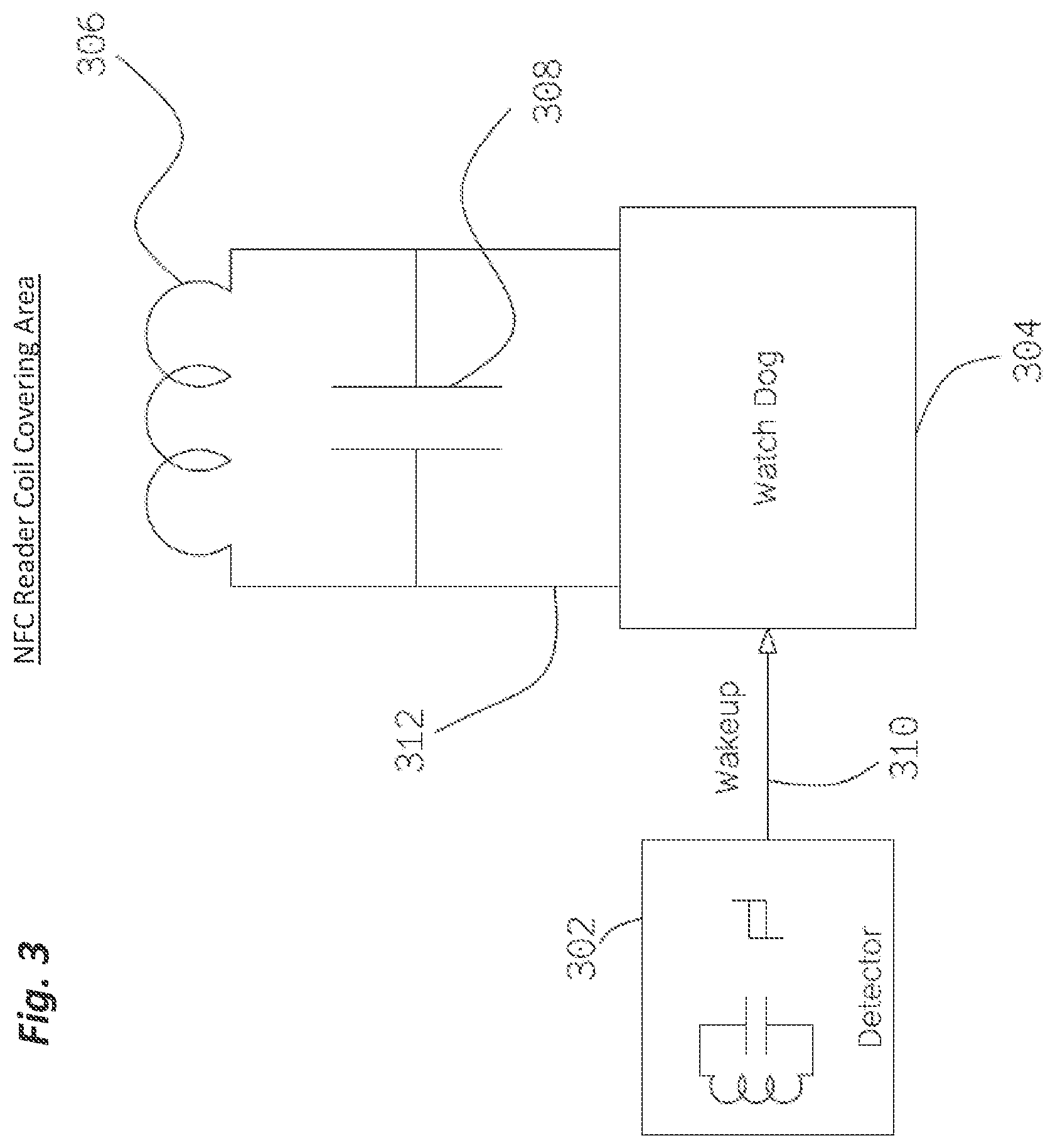
[0014] FIG. 3 is a schematic view of an exemplary embodiment of an NFC for activating an NFC security security system when an external NFC reader is placed proximate to an NFC reading zone that contains an NFC tag.
[0015] FIG. 4 is a schematic view of an exemplary embodiment of an NFC detector for activating the NFC security security system when an external NFC reader is placed close to an inductive coil.
[0016] FIG. 5 is a schematic view of an exemplary embodiment of an NFC detector incorporating a counter circuit recording the number of instances that an external NFC reader is placed proximate to a receiving inductive coil of an NFC detector.
[0017] FIG. 6 is an exemplary flowchart showing an order of operations for an NFC security system.
DETAILED DESCRIPTION
[0018] Aspects of the invention are disclosed in the following description and related drawings directed to specific embodiments of the invention. Alternate embodiments may be devised without departing from the spirit or the scope of the invention. Additionally, well-known elements of exemplary embodiments of the invention will not be described in detail or will be omitted so as not to obscure the relevant details of the invention. Further, to facilitate an understanding of the description discussion of several terms used herein follows.
[0019] As used herein, the word "exemplary" means "serving as an example, instance or illustration." The embodiments described herein are not limiting, but rather are exemplary only. It should be understood that the described embodiments are not necessarily to be construed as preferred or advantageous over other embodiments. Moreover, the terms "embodiments of the invention", "embodiments" or "invention" do not require that all embodiments of the invention include the discussed feature, advantage or mode of operation.
[0020] Generally referring to FIGS. 1-6, exemplary embodiments disclosed herein may describe NFC security systems, sometimes referred to as NFC Watch Dog systems. In some exemplary embodiments, queries transmitted by the external NFC reader in reader/writer mode can be used to sense when a mobile phone is placed proximate to a specific location on a display surface using NFC detector circuitry.
[0021] An exemplary NFC security system may include an NFC reader, a security controller 111 and an inductive coil with impedance matching circuits. Functions of an NFC security system may be to detect unauthorized tags, disable such tags and alert maintenance personnel of a problem.
[0022] The detection of unauthorized tags 216 may be achieved by an NFC reader component transmitting NFC interrogation commands to an inductive coil of a detector. The inductive coil may distribute magnetic energy over the surface of the display that is being interrogated for unauthorized tags. A security controller 111 of an exemplary NFC security system may not perform interrogation on a constant basis, so that it may not interfere with a communication channel of an external NFC reader and an NFC device such as an NFC tag. The security controller 111 may activate reading on regular intervals or conditionally upon the state of a signal line, such as from another controller or sensor. The NFC detector of the detector circuit may be configured to send a signal to the NFC security system when a phone is placed proximate a specific location on the surface of a display.
[0023] Exemplary embodiments may require less complex circuit design than other solutions utilizing an NFC reader circuit. In some exemplary embodiments, the major elements of the NFC detector circuit may include an inductive receiver coil, an RF demodulator and a threshold detector. The NFC detector circuit may not decode the data signal of an external NFC reader in order to detect its proximate placement on a display surface. Additionally, the NFC detector circuit may be designed only for receiving RF signals and may not transmit RF signals, unlike an NFC reader. As such, multiple NFC detectors or detector circuits may be integrated into a display system without interfering with a communication channel of an external NFC reader or an intended NFC communication device such as an NFC tag.
[0024] In an exemplary embodiment, a display may include two or more NFC detector circuits positioned apart over the display surface so that users may indicate choices using placement of the mobile phone based on display indicia. For example, if a user of the display places an external reader such as a mobile phone directly over one of the NFC detectors of a detector circuit, then the display may indicate the user's selection, such as departure information. In the same example, a mobile phone placed over another NFC detector may indicate arrival information is being desired. Once a selection has been made by the user, the NFC tag memory may be formatted with the appropriate NDEF message, which in this example may include a link to either the arrival or departure information.
[0025] In another exemplary embodiment, a display may include multiple NFC detectors embedded over a surface. The display system may detect when the user moves the mobile phone along a path recognized by the display system, which may be referred to as a gesture, such as, for example, following a circular path along display indicia. When a gesture is recognized by the display system, a custom NFC message may be prepared for the user, which may be read by the NFC enabled mobile phone.
[0026] Exemplary embodiments may reduce power consumption in systems that utilize the NFC detector to control the active state of NFC transceivers, such as NFC readers and NFC peer-to-peer mode devices. An internal NFC reader 212A used in the NFC security system may want to transmit enough power to interrogate unauthorized tags that could be affixed to the display. The power for the interrogation function may be up to 4 watts, depending on the desired operating range and size of the transmitting NFC coil. Utilizing an NFC detector to control the active state of an NFC reader may reduce power consumption, for example by limiting interrogation functions to necessary conditions, such as when an external NFC reader is brought close to the display.
[0027] Additionally, utilizing the NFC detector for lower power consumption may enable a display system to operate from battery power instead of a main connection. In an exemplary embodiment, the display system may use a battery as backup power for situations in which the main power has been interrupted.
[0028] In another exemplary embodiment, the NFC detector may control operating modes of an NFC peer-to-peer mode reader, which may function to transmit NFC messages via Simple NDEF Exchange Protocol (SNEP) to the external NFC reader. In this exemplary embodiment, the display system may be battery powered, which may require that the peer-to-peer reader be activated only when an external NFC reader is present.
[0029] Referring now to exemplary FIG. 1, a schematic view of an exemplary embodiment of an NFC detector circuit may be shown. The elements of the detector circuit may include a near field inductive receiver coil 102 with impedance matching element 104, a demodulator 106, and a threshold detector 108.
[0030] The inductive receiver coil 102 may include a distributed inductor adapted to be receptive to alternating magnetic fields in the vicinity of the coil. The capacitor 104 may form an impedance matching circuit between the inductive receiver coil 102 and a transmission line 110, such as, for example, a 50 ohm transmission line.
[0031] The impedance matching circuit may be adapted to enable a low loss transmission of signal energy between the inductive receiving coil 102 and the transmission line 110, which may be connected to other circuits of the NFC detector.
[0032] The capacitor 104 in FIG. 1 is only one exemplary embodiment of an impedance matching circuit; other circuit configurations may be possible which may, for example, increase the bandwidth across the frequency band but require the use of more complex circuitry for implementing the impedance matching circuit. Such impedance matching circuits may include any impedance matching circuit known in the art.
[0033] In this exemplary embodiment, when an external NFC reader is proximate to the NFC detector of the detector circuit, an RF signal on transmission line 110 may be received by the demodulator circuit 106 for recovery of the original data signal without an RF carrier wave. The demodulator 106 in FIG. 1 can be a diode envelope detector, used, for example, because of relatively simple circuit and low power consumption. However, if better signal discrimination or input filtering is desired, any other demodulator circuit known in the art may be implemented with the associated design trade-off in circuit complexity and power consumption. The output signal of the demodulator 106 may include DC voltage pulses 116 which may travel via the transmission line 112 to the threshold detector circuit 108.
[0034] The threshold detector circuit 108 may drive a two state output signal, normally in the "disabled" state, to the "enabled" state when the output voltage from the demodulator exceeds the "enabled" or high threshold voltage point. Separating the high and low threshold levels of the threshold detector 108 may form a hysteresis function, such that the "enabled" output state cannot be reset back to the "disabled" state, until the input voltage is lower than the "disabled" threshold voltage point. As such, the output state of the threshold detector may not oscillate if the input voltage oscillates around either voltage threshold point. The threshold detector 108 in exemplary FIG. 1 can be a low power Schmitt trigger circuit. The Schmitt trigger circuit may be utilized as it is a well-documented circuit commonly used in many circuit applications; therefore the design and implementation of a Schmitt trigger is not described in detail here. However, other threshold detectors known in the art may be implemented, as desired. The output of threshold detector 108 may drive the two state output signal through the transmission line 114 to digital output circuits for the host system 118. The digital output 118 to the host system may be implemented with necessary circuitry to buffer or latch the output state of the NFC detector for immediate or later use by the host system input circuitry.
[0035] FIG. 1A of the present invention illustrates a display 212 having both an authorized NFC tag 218 and an unauthorized tag 216. The present invention contemplates that the internal NFC reader 212A of the detector circuit 302 detects an unauthorized tag 216 applied to the display 212 and creates a signal in order to disable the unauthorized tag 216.
[0036] FIG. 2 is a schematic view of an exemplary embodiment of an NFC detector of a detector circuit that may control the illumination of Light Emitting Diodes (LEDs) integrated into an NFC reading zone. The circuit may be adapted to indicate to the user that the external NFC reader device 214 has been placed in a proper or desired region for reading the intended NFC tag. The inductive element of the NFC detector and the LEDs may be located proximate to the NFC reading zone. Other circuit elements may not have critical placement with respect to the display surface and may be placed where best suited or desired. The NFC detector 202 in the exemplary circuit may drive the voltage of the control line 220 to either the "enabled" state value when an external NFC reader is proximate to the NFC detector, or to the "disabled" state value when no external NFC reader is proximate to the detector. The LED driver circuit 204 may adjust the voltage and current source on line 222 relative to ground 210 to the appropriate condition to illuminate the LEDs 206 and 208 inside the display located near the NFC reading zone.
[0037] FIG. 3 is a schematic view of an exemplary embodiment of an NFC detector of a detector circuit that may activate an NFC security system when an external NFC reader, such as a mobile phone, is placed proximate to an NFC reading zone that contains an NFC tag. The NFC detector circuit 302 may drive the line 310 with an output voltage level signifying the "enabled" state to the security system 304. Upon sensing the "enabled" state voltage on the wakeup control line 310, the security system may perform an NFC inventory command with an internal NFC reader 212A. The internal NFC reader 212A may transmit NFC air protocol commands through the cable 312 to the matching network 308 and then to the transmitting coil 306. If the security system discovers an unauthorized tag, then appropriate actions may be taken, such as, for example, disabling the tag or sending a help request to maintenance personnel. When the NFC security function is complete, the system may transition to a sleep mode for minimal power consumption. Subsequently, the NFC detector circuit may remain idle for a specified time, to allow the external NFC reader to transfer contents of the authorized NFC tag without interference from the NFC security system.
[0038] FIG. 4 is a schematic view of an exemplary embodiment of an NFC detector that may activate the NFC security system when an external NFC reader, such as a mobile phone, is placed close to a common inductive coil 408. The inductive coil may include a common element to both the detector and the security system. The use of a common coil may be such that each circuit establishes an exclusive connection to the cable 412 that connects to the common coil 408. A "detect" state and a "security" state may be used for selecting a connection to a common NFC coil 408. The initial and nominal state for the system may be the "detect" state. When the display system is in the "detect" state, the NFC detector circuit may have priority control of the common NFC coil 408, while the security system may be disconnected from the common coil 408 and configured to a low power sleep mode. The NFC detector may continually monitor for signals from an external NFC reader, such as a mobile phone. Upon detecting a signal from an external reader, the system may transition to the "security" state. In the "security" state, the NFC detector may disconnect from the common NFC coil 408 by open circuiting the connection to the cable 412. The NFC detector may then drive the voltage of the wake up line 406 to the "enabled" state. The security system may detect the "enabled" state of the wake up line 406 and may transition to the "security" state. Upon transitioning to the "security" state, the security system may connect the common NFC coil 408 by switching the circuit connection of the system to cable 412 from an open circuit to a short circuit. The security system may then issue NFC inventory commands to the common coil 408 to check for unauthorized tags affixed to the display. If unauthorized tags are affixed to the display, the security system may perform actions such as attempting to disable the unauthorized tag or signaling a request for maintenance personnel to remove the unauthorized tag. Upon completion of the security operation, the security system may open the circuit connection to cable 412, may signal to the NFC detector that the security mode is complete, and may then transition to the low power operating state. The system state may then be returned to a "detect" mode. Upon switching from "security" state to "detect" state, the NFC detector circuit may remain idle for a specified time to allow the external NFC reader to transfer the contents of the authorized NFC tag without interference from the NFC security system.
[0039] FIG. 5 is a schematic view of an exemplary embodiment of an NFC detector 502 that may incorporate a counter circuit 504 that may record the number of instances that an external NFC reader, such as a mobile phone, is placed proximate to a receiving inductive coil of an NFC detector. The stored value of the counter circuit may be used, for example, to determine metrics for the effectiveness of the display. The signal line 510 may be routed to other functions 506 that sense the state of the NFC detector output signal. The other functions 506 may include, for example, an NFC security system or an interactive display system as described above.
[0040] FIG. 6 is an exemplary flow chart describing aspects of the NFC security system. In this exemplary embodiment, time 602 may represent any time after an NFC security system is implemented and/or triggered. The system can include sensors 604 which work to detect any undesired or rogue NFC signals. Thus, if sensors 604 are active and do not detect any rogue signals, the system may go into sleep 606 mode. If sensors 604 are active and detect a rogue signal, a desired response action 610 may be taken. The response action can include blocking the rogue signal or destroying the rogue device. If the action 610 is successful, the system can return to sleep 606 mode. If the action is unsuccessful, the system may try to take the desired action 610 again, or a signal may be dispatched to appropriate personnel. As can be appreciated by the above, any other courses of action using other components may also be utilized.
[0041] The foregoing description and accompanying figures illustrate the principles, preferred embodiments and modes of operation of the invention. However, the invention should not be construed as being limited to the particular embodiments discussed above. Additional variations of the embodiments discussed above will be appreciated by those skilled in the art.
[0042] Therefore, the above-described embodiments should be regarded as illustrative rather than restrictive. Accordingly, it should be appreciated that variations to those embodiments can be made by those skilled in the art without departing from the scope of the invention as defined by the following claims.
* * * * *
D00000
D00001
D00002
D00003
D00004
D00005
D00006
XML
uspto.report is an independent third-party trademark research tool that is not affiliated, endorsed, or sponsored by the United States Patent and Trademark Office (USPTO) or any other governmental organization. The information provided by uspto.report is based on publicly available data at the time of writing and is intended for informational purposes only.
While we strive to provide accurate and up-to-date information, we do not guarantee the accuracy, completeness, reliability, or suitability of the information displayed on this site. The use of this site is at your own risk. Any reliance you place on such information is therefore strictly at your own risk.
All official trademark data, including owner information, should be verified by visiting the official USPTO website at www.uspto.gov. This site is not intended to replace professional legal advice and should not be used as a substitute for consulting with a legal professional who is knowledgeable about trademark law.