Oven Appliances And Methods Of Operation For Updating Default Temperatures
Armstrong; James Lee
U.S. patent application number 16/006953 was filed with the patent office on 2019-12-19 for oven appliances and methods of operation for updating default temperatures. The applicant listed for this patent is Haier US Appliance Solutions, Inc.. Invention is credited to James Lee Armstrong.
| Application Number | 20190383495 16/006953 |
| Document ID | / |
| Family ID | 68839807 |
| Filed Date | 2019-12-19 |


| United States Patent Application | 20190383495 |
| Kind Code | A1 |
| Armstrong; James Lee | December 19, 2019 |
OVEN APPLIANCES AND METHODS OF OPERATION FOR UPDATING DEFAULT TEMPERATURES
Abstract
An oven appliance and methods of operating an oven appliance are provided herein. The oven appliance may include a cabinet defining a cooking chamber, a heating element within the cabinet to heat the cooking chamber, a user interface attached to the cabinet, and a controller operably coupled to the heating element and the user interface. The controller may be configured to initiate a cooking operation that includes establishing a preferred default temperature.
| Inventors: | Armstrong; James Lee; (Louisville, KY) | ||||||||||
| Applicant: |
|
||||||||||
|---|---|---|---|---|---|---|---|---|---|---|---|
| Family ID: | 68839807 | ||||||||||
| Appl. No.: | 16/006953 | ||||||||||
| Filed: | June 13, 2018 |
| Current U.S. Class: | 1/1 |
| Current CPC Class: | F24C 7/088 20130101; F24C 7/085 20130101 |
| International Class: | F24C 7/08 20060101 F24C007/08 |
Claims
1. A method of operating an oven appliance comprising: recording a plurality of historic heating cycles for the oven appliance, each historic heating cycle comprising an input temperature setting received at a user interface of the oven appliance; determining a preferred temperature setting based on the input temperatures of the plurality of historic heating cycles; comparing the preferred temperature setting to a previous default temperature setting; establishing the preferred temperature setting as a current default temperature setting in response to the preferred temperature setting diverging from the previous default temperature setting; receiving an activation signal from the user interface; and directing a cooking chamber of the oven appliance to the current default temperature setting in response to receiving the activation signal.
2. The method of claim 1, wherein recording includes transmitting the plurality of historic heating cycles to a remote server spaced apart from the oven appliance.
3. The method of claim 1, wherein the plurality of historic heating cycles comprises a plurality of heating cycles performed during a dynamic time period.
4. The method of claim 1, wherein the plurality of historic heating cycles comprises a minimum number of heating cycles.
5. The method of claim 1, wherein each historic heating cycle comprises receiving an activation signal for a cooking chamber of the oven appliance, and receiving a cancellation signal for the cooking chamber of the oven appliance.
6. The method of claim 1, wherein determining the preferred temperature setting comprises identifying a median temperature setting of the plurality of historic heating cycles, wherein the preferred temperature setting is the median temperature setting.
7. The method of claim 1, wherein establishing the preferred temperature setting as the current default temperature setting comprises detecting the preferred temperature setting diverges from the previous default temperature setting by a predetermined percentage.
8. The method of claim 1, further comprising establishing the previous default temperature setting as the current default temperature setting in response to the preferred temperature setting failing to diverge from the previous default temperature setting.
9. The method of claim 1, further comprising receiving the preferred temperature setting from a remote server spaced apart from the oven appliance.
10. The method of claim 1, wherein the activation signal is initiated in response to engagement of a bake input at the user interface.
11. An oven appliance comprising: a cabinet defining a cooking chamber; a heating element within the cabinet to heat the cooking chamber; a user interface attached to the cabinet; and a controller operably coupled to the heating element and the user interface, the controller being configured to initiate a cooking operation comprising recording a plurality of historic heating cycles for the oven appliance, each historic heating cycle comprising an input temperature setting received at the user interface, determining a preferred temperature setting based on the input temperatures of the plurality of historic heating cycles, comparing the preferred temperature setting to a previous default temperature setting, establishing the preferred temperature setting as a current default temperature setting in response to the preferred temperature setting diverging from the previous default temperature setting, receiving an activation signal from the user interface, and directing a cooking chamber of the oven appliance to the current default temperature setting in response to receiving the activation signal.
12. The oven appliance of claim 11, wherein recording includes transmitting the plurality of historic heating cycles to a remote server spaced apart from the oven appliance.
13. The oven appliance of claim 11, wherein the plurality of historic heating cycles comprises a plurality of heating cycles performed during a dynamic time period.
14. The oven appliance of claim 11, wherein the plurality of historic heating cycles comprises a minimum number of heating cycles.
15. The oven appliance of claim 11, wherein each historic heating cycle comprises receiving an activation signal for the cooking chamber, and receiving a cancellation signal for the cooking chamber.
16. The oven appliance of claim 11, wherein determining the preferred temperature setting comprises identifying a median temperature setting of the plurality of historic heating cycles, wherein the preferred temperature setting is the median temperature setting.
17. The oven appliance of claim 11, wherein establishing the preferred temperature setting as the current default temperature setting comprises detecting the preferred temperature setting diverges from the previous default temperature setting by a predetermined percentage.
18. The oven appliance of claim 11, wherein the cooking operation further comprises establishing the previous default temperature setting as a current default temperature setting in response to the preferred temperature setting failing to diverge from the previous default temperature setting.
19. The oven appliance of claim 11, wherein the cooking operation further comprises receiving the preferred temperature setting from a remote server spaced apart from the oven appliance.
20. The oven appliance of claim 11, wherein the activation signal is initiated in response to engagement of a bake input at the user interface.
Description
FIELD OF THE INVENTION
[0001] The present subject matter relates generally to oven appliances, and more particularly to oven appliances and methods with features for updating a default temperature setting.
BACKGROUND OF THE INVENTION
[0002] Conventional residential and commercial oven appliances generally include a cabinet that defines a cooking chamber for receipt of food items for cooking. Heating elements are positioned within the cooking chamber to provide heat to food items located therein. The heating elements can include, for example, radiant heating elements, such as a bake heating assembly positioned at a bottom of the cooking chamber or a broil heating assembly positioned at a top of the cooking chamber.
[0003] In some conventional oven appliances, a user interface is provided on or adjacent to the oven appliance. Typically, once the oven is activated or a heating operation is selected (e.g., a bake operation), the user interface provides a default temperature setting for the cooking chamber. For instance, a temperature setting of 350.degree. Fahrenheit is the default temperature setting for many oven appliances sold within the United States. Without further selection or input, the oven appliance may then heat the cooking chamber to the value (i.e., temperature) of the default temperature setting. If the user wishes to have the cooking chamber operate at a temperature setting that is different from the default temperature setting, the user must often press or select a new temperature setting after the oven has been activated or a heating operation has been selected.
[0004] Typically, any default temperature setting is programmed within the oven appliance during its manufacture and may not be changed. Although the default temperature setting may be the temperature at which most cooking operations are performed for many or most consumers, there may be consumers or instances where the default temperature setting is rarely used. This may lead to frustration for some consumers, since they will be required to routinely adjust the temperature setting for the oven appliance. Some consumers may wish to change the default temperature setting, but may not readily know what an appropriate temperature setting would be. Moreover, in many instances it is difficult, if not impossible, for a consumer or user to change any of the default settings of an oven appliance.
[0005] Therefore, further improvements would be useful for adjusting a default temperature setting in an oven appliance. In particular, it may be advantageous to provide an oven appliance or methods that permit adjustments to the settings of an oven appliance without the need for direct controller input from a user.
BRIEF DESCRIPTION OF THE INVENTION
[0006] Aspects and advantages of the invention will be set forth in part in the following description, or may be obvious from the description, or may be learned through practice of the invention.
[0007] In one exemplary aspect of the present disclosure, a method for operating an oven appliance is provided. The method may include recording a plurality of historic heating cycles. Each historic heating cycle may include an input temperature setting received at a user interface of the oven appliance. The method may include determining a preferred temperature setting based on the input temperatures of the plurality of historic heating cycles. The method may further include comparing the preferred temperature setting to a previous default temperature setting. The method may further include establishing the preferred temperature setting as a current default temperature setting in response to the preferred temperature setting diverging from the previous default temperature setting. The method may still further include receiving an activation signal from the user interface. The method may also include directing a cooking chamber of the oven appliance to the current default temperature setting in response to receiving the activation signal.
[0008] In another exemplary aspect of the present disclosure, an oven appliance is provided. The oven appliance may include a cabinet defining a cooking chamber, a heating element within the cabinet to heat the cooking chamber, a user interface attached to the cabinet, and a controller operably coupled to the heating element and the user interface. The controller may be configured to initiate a cooking operation. The cooking operation may include recording a plurality of historic heating cycles for the oven appliance, determining a preferred temperature setting based on an input temperature of the plurality of historic heating cycles, comparing the preferred temperature setting to a previous default temperature setting, establishing the preferred temperature setting as a current default temperature setting in response to the preferred temperature setting diverging from the previous default temperature setting, receiving an activation signal from the user interface, and directing a cooking chamber of the oven appliance to the current default temperature setting in response to receiving the activation signal. Each historic heating cycle may include an input temperature setting received at the user interface.
[0009] These and other features, aspects and advantages of the present invention will become better understood with reference to the following description and appended claims. The accompanying drawings, which are incorporated in and constitute a part of this specification, illustrate embodiments of the invention and, together with the description, serve to explain the principles of the invention.
BRIEF DESCRIPTION OF THE DRAWINGS
[0010] A full and enabling disclosure of the present invention, including the best mode thereof, directed to one of ordinary skill in the art, is set forth in the specification, which makes reference to the appended figures.
[0011] FIG. 1 provides a perspective view of an oven appliance according to exemplary embodiments of the present disclosure.
[0012] FIG. 2 provides a section view of the exemplary oven appliance of FIG. 1, taken along the line 2-2.
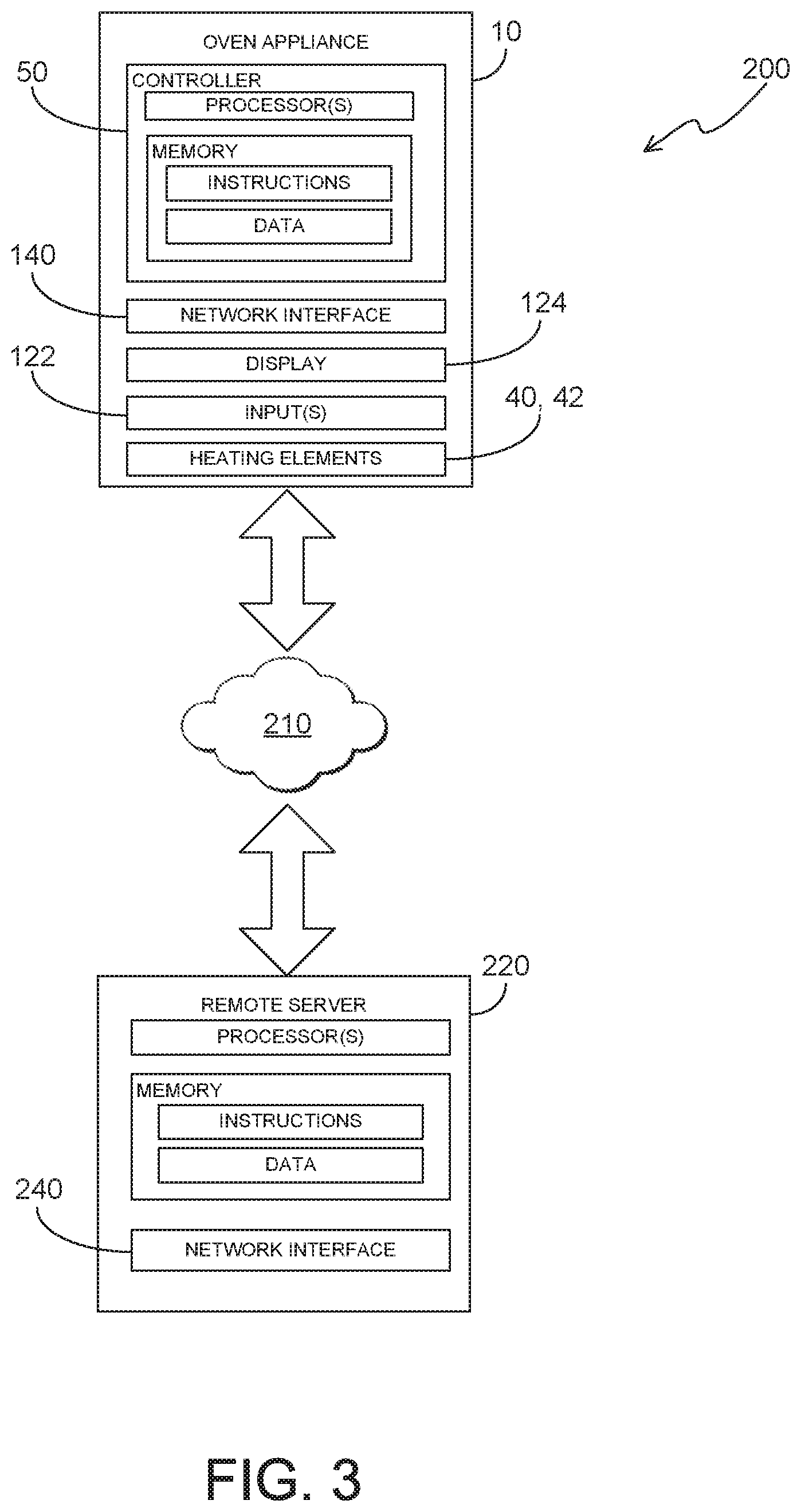
[0013] FIG. 3 provides a schematic view of a servicing system according to exemplary embodiments of the present disclosure.
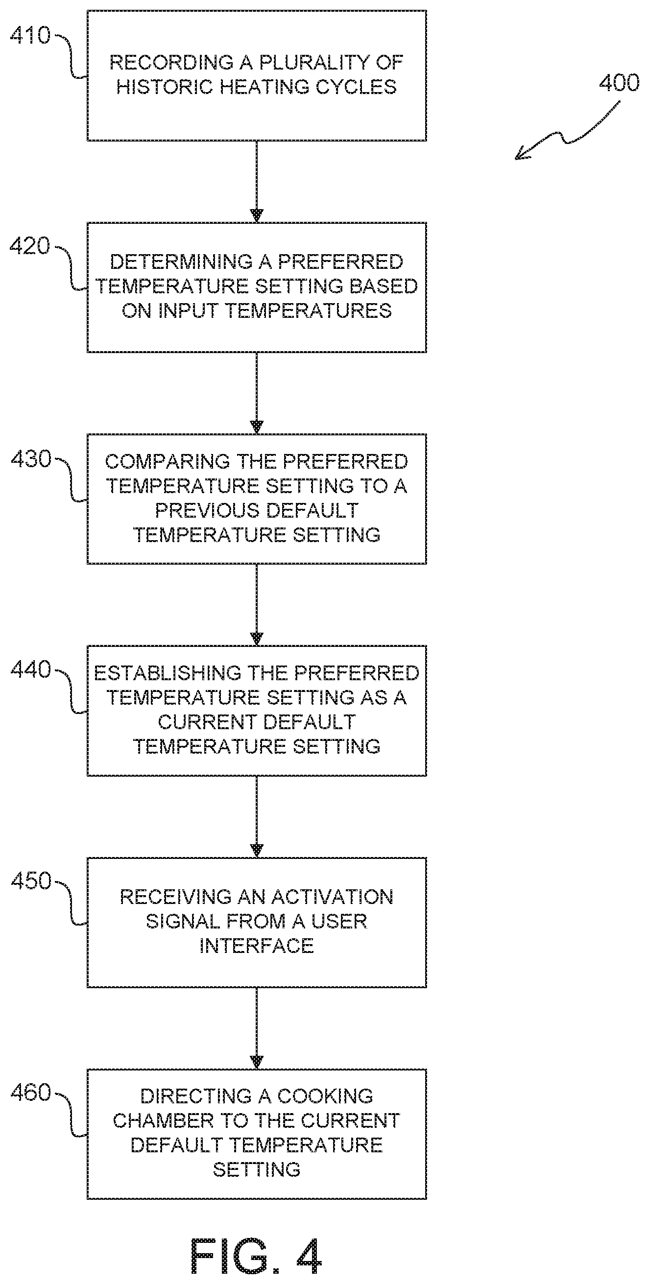
[0014] FIG. 4 provides a flow chart illustrating a method of operating an oven appliance according to exemplary embodiments of the present disclosure.
DETAILED DESCRIPTION
[0015] Reference now will be made in detail to embodiments of the invention, one or more examples of which are illustrated in the drawings. Each example is provided by way of explanation of the invention, not limitation of the invention. In fact, it will be apparent to those skilled in the art that various modifications and variations can be made in the present invention without departing from the scope or spirit of the invention. For instance, features illustrated or described as part of one embodiment can be used with another embodiment to yield a still further embodiment. Thus, it is intended that the present invention covers such modifications and variations as come within the scope of the appended claims and their equivalents.
[0016] It is noted that, for the purposes of the present disclosure, the terms "includes" and "including" are intended to be inclusive in a manner similar to the term "comprising." Similarly, the term "or" is generally intended to be inclusive (i.e., "A or B" is intended to mean "A or B or both").
[0017] FIG. 1 provides a perspective view of an oven appliance 10 according to an exemplary embodiment of the present disclosure. FIG. 2 provides a section view of oven appliance 10 taken along the 2-2 line of FIG. 1. As may be seen, oven appliance 10 defines a vertical direction V, a lateral direction L and a transverse direction T. The vertical direction V, the lateral direction L and the transverse direction T are mutually perpendicular and form an orthogonal direction system. Oven appliance 10 is provided by way of example only and is not intended to limit the present subject matter in any aspect. Thus, the present subject matter may be used with other oven appliance configurations (e.g., that define one or more interior cavities for the receipt of food or having different pan or rack arrangements than what is shown in FIG. 2). Further, the present subject matter may be used in a stand-alone cooktop, range appliance, or any other suitable appliance.
[0018] Oven appliance 10 generally includes a cooking assembly. In particular, the cooking assembly may include one or more heating elements. For example, in some embodiments, the cooking assembly, and thus the oven appliance 10 includes an insulated cabinet 12 with an interior cooking chamber 14 defined by an interior surface 15 of cabinet 12. Cooking chamber 14 is configured for the receipt of one or more food items to be cooked. Oven appliance 10 includes a door 16 rotatably mounted to cabinet 12 (e.g., with a hinge--not shown). A handle 18 may be mounted to door 16 and assists a user with opening and closing door 16 in order to access cooking chamber 14. For example, a user can pull on handle 18 to open or close door 16 and access cooking chamber 14.
[0019] In some embodiments, oven appliance 10 includes a seal (not shown) between door 16 and cabinet 12 that assists with maintaining heat and cooking fumes within cooking chamber 14 when door 16 is closed as shown in FIG. 2. Multiple parallel glass panes 22 may provide for viewing the contents of cooking chamber 14 when door 16 is closed and assist with insulating cooking chamber 14. A baking rack 24 is positioned in cooking chamber 14 for the receipt of food items or utensils containing food items. Baking rack 24 is slidably received onto embossed ribs or sliding rails 26 such that rack 24 may be conveniently moved into and out of cooking chamber 14 when door 16 is open.
[0020] In certain embodiments, a gas fueled or electric bottom heating element 40 (e.g., a gas burner, a radiant heating element, microwave heating element, or a resistive heating element) is positioned in cabinet 12, for example, at a bottom portion 30 of cabinet 12. Bottom heating element 40 is used to heat cooking chamber 14 for both cooking and cleaning of oven appliance 10. The size and heat output of bottom heating element 40 can be selected based on, for example, the size of oven appliance 10.
[0021] In additional or alternative embodiments, a top heating element 42 (e.g., a gas burner, a radiant heating element, or a resistive heating element) is positioned in cooking chamber 14 of cabinet 12, for example, at a top portion 32 of cabinet 12. Top heating element 42 is used to heat cooking chamber 14 for both cooking/broiling and cleaning of oven appliance 10. Like bottom heating element 40, the size and heat output of top heating element 42 can be selected based on for example, the size of oven appliance 10.
[0022] As shown in FIG. 2, in certain embodiments, a cooling air flow passageway 28 can be provided within cabinet 12 between cooking chamber 14 and cooktop 100. For example, a portion of passageway 28 may be between cooking chamber 14 and cooktop 100 along a vertical direction V. Passageway 28 is shown schematically in the figures. As will be understood by one of skill in the art using the teachings disclosed herein, cooling air flow passageway 28 may have a variety of configurations other than as shown. Air flowing through passageway 28 can provide convective cooling.
[0023] In optional embodiments, the oven appliance 10 additionally includes a cooktop 100. Cooktop 100 may be disposed on the cabinet 12 such that the total volume of cabinet 12 is generally divided between the cooking chamber 14 and cooktop 100. As shown, cooktop 100 may include a top panel 104. By way of example, top panel 104 may be constructed of glass, ceramics, enameled steel, and combinations thereof. Heating assemblies 106 (e.g., induction heating elements, resistive heating elements, radiant heating elements, or gas burners) may be mounted, for example, on or below the top panel 104. While shown with four heating assemblies 106 in the exemplary embodiment of FIG. 1, cooktop appliance 100 may include any number of heating assemblies 106 in alternative exemplary embodiments. Heating assemblies 106 can also have various diameters. For example, each heating assembly of heating assemblies 106 can have a different diameter, the same diameter, or any suitable combination thereof.
[0024] As shown, oven appliance 10 includes a user interface panel 120, which may be located as shown, within convenient reach of a user of the oven appliance 10. User interface panel 120 is generally a component that allows a user to interact with the oven appliance 10 to, for example, turn various heating elements (such as heating elements 40, 42, 106) on and off, adjust the temperature of the heating elements, set built-in timers, etc. Although user interface panel 120 is shown mounted to a backsplash fixed to cabinet 102, alternative embodiments may provide user interface panel 120 at another suitable location (e.g., on a front portion of cabinet 102 above door 16).
[0025] In some embodiments, a user interface panel 120 may include one or more user-interface inputs 122 and a graphical display 124, which may be separate from or integrated with the user-interface inputs 122. The user-interface element 122 may include analog control elements (e.g., knobs, dials, or buttons) or digital control elements, such as a touchscreen comprising a plurality of elements thereon. Various commands for a user to select through the engagement with the user-interface inputs 122 may be displayed (e.g., by touchscreen at the inputs 122 or by the graphical display 124), and detection of the user selecting a specific command may be determined by the controller 50, which is in communication with the user-interface inputs 122, based on electrical signals therefrom. Additionally or alternatively, graphical display 124 may generally deliver certain information to the user, which may be based on user selections and interaction with the inputs 122, such as whether a one or more heating elements 40, 42 within cooking chamber 14 are activated or the temperature at which cooking chamber 14 is set. In certain embodiments, a discrete bake input is included with the inputs 122. User engagement of the bake input may activate the oven appliance 10 or initiate heating within cooking chamber 14 (e.g., such that cooking chamber 14 is directed to a default temperature setting).
[0026] Turning now to FIG. 3, a schematic view is provided of a servicing system 200, including oven appliance 10, according to exemplary embodiments of the present disclosure. Generally, oven appliance 10 includes a controller 50 that controls operation of the various components of the oven appliance 10. Controller 50 may include a memory (e.g., non-transitive media) and microprocessor, such as a general or special purpose microprocessor operable to execute programming instructions or micro-control code associated with a cleaning cycle. The memory may represent random access memory such RAM, ROM, EEPROM, EPROM, flash memory devices, magnetic disks, etc., and combinations thereof. The memory devices can store data and instructions that are executed by the processor to cause oven appliance 10 to perform various operations. For example, instructions could be instructions for directing activation of one or more of the heating elements 40, 42. Instructions could further be for receiving/transmitting log data signals (e.g., signals corresponding to performance or activation of the oven appliance 10, such as past or historic temperature settings that have been selected for cooking cycles within the cooking chamber 14), recording log data as one or more log data sets over time (e.g., within memory), etc. User interface panel (e.g., inputs 122 and display 124) and other components of oven appliance 10 may be in communication with controller 50 via one or more signal lines or shared communication busses.
[0027] In some embodiments, controller 50 includes a network interface 140 such that oven appliance 10 can connect to and communicate over one or more networks (e.g., network 210) with one or more network nodes. Network interface 140 can be an onboard component of controller 50 or it can be a separate, off board component. Controller 50 can also include one or more transmitting, receiving, or transceiving components for transmitting/receiving communications with other devices communicatively coupled with oven appliance 10. Additionally or alternatively, one or more transmitting, receiving, or transceiving components can be located off board controller 50.
[0028] Network 210 can be any suitable type of network, such as a local area network (e.g., intranet), wide area network (e.g., internet), low power wireless networks [e.g., Bluetooth Low Energy (BLE)], or some combination thereof and can include any number of wired or wireless links. In general, communication over network 210 can be carried via any type of wired or wireless connection, using a wide variety of communication protocols (e.g., TCP/IP, HTTP, SMTP, FTP), encodings or formats (e.g., HTML, XML), or protection schemes (e.g., VPN, secure HTTP, SSL).
[0029] In some embodiments, a remote server 220, such as a web server, is in operable communication with oven appliance 10. The remote server 220 can be used to host a service platform or cloud-based application. Additionally or alternatively, remote server 220 can be used to host an information database (e.g., recorded log data, historic heating cycles, temperature settings, or other relevant data). Remote server 220 can be implemented using any suitable computing device(s). Remote server 220 may include one or more processors and one or more memory devices (i.e., memory). The one or more processors can be any suitable processing device (e.g., a processor core, a microprocessor, an ASIC, a FPGA, a microcontroller, etc.) and can be one processor or a plurality of processors that are operatively connected. The memory device can include one or more non-transitory computer-readable storage mediums, such as RAM, ROM, EEPROM, EPROM, flash memory devices, magnetic disks, etc., and combinations thereof. The memory devices can store data and instructions which are executed by the processors to cause remote server 220 to perform operations. For example, instructions could be instructions for receiving/transmitting files related to log data, historic heating cycles, temperature settings, etc.
[0030] The memory devices may also include data, such as log data, historic heating cycles, temperature settings, etc., that can be retrieved, manipulated, created, or stored by processors. The data can be stored in one or more databases. The one or more databases can be connected to remote server 220 by a high bandwidth LAN or WAN, or can also be connected to remote server 220 through network 210. Optionally, the one or more databases can be split up so that they are located in multiple locales.
[0031] Remote server 220 includes a network interface 240 such that interactive remote server 220 can connect to and communicate over one or more networks (e.g., network 210) with one or more network nodes. Network interface 240 can be an onboard component or it can be a separate, off board component. In turn, remote server 220 can exchange data with one or more nodes over the network 210. In particular, remote server 220 can exchange data with oven appliance 10. Although not pictured, it is understood that remote server 220 may further exchange data with any number of client devices over the network 210. The client devices can be any suitable type of computing device, such as a general purpose computer, special purpose computer, laptop, desktop, integrated circuit, mobile device, smartphone, tablet, or another suitable computing device. Information or signals (e.g., relating log data, historic heating cycles, temperature settings, etc.) may thus be exchanged between oven appliance 10 and various separate client devices through remote server 220.
[0032] Referring now to FIG. 4, various methods (e.g., method 400) may be provided for use with oven appliance 10 or system 200 in accordance with the present disclosure. In general, the various steps of methods as disclosed herein may, in exemplary embodiments, be performed by the controller 50 as part of an operation that the controller 50 is configured to initiate (e.g., one or more cooking operations). During such methods, controller 50 may receive inputs and transmit outputs from various other portions of the system 200. For example, controller 50 may send signals to and receive signals from user interface 120, inputs 122, heating elements 40, 42, remote server 220, as well as other suitable components. Additionally or alternatively, one or more of the recited steps may be performed with, or in part by, the remote server 220.
[0033] The present methods may advantageously permit selection and use of a common or preferable default temperature setting. Moreover, the methods may advantageously occur automatically without direct user input or selection of the default temperature.
[0034] FIG. 4 depicts steps performed in a particular order for purpose of illustration and discussion. Those of ordinary skill in the art, using the disclosures provided herein, will understand that (except as otherwise indicated) the steps of any of the methods disclosed herein can be modified, adapted, rearranged, omitted, or expanded in various ways without deviating from the scope of the present disclosure.
[0035] At 410, the method 400 includes recording a plurality of historic heating cycles for the oven appliance. Generally, the historic heating cycles represent past operations or instances of use of the oven appliance. Each historic heating cycle includes an input temperature setting received at a user interface of the oven appliance. In other words, each recorded instance of a historic heating cycle includes data or recorded information regarding what the temperature setting was for a corresponding historic heating cycle. The input temperature setting may be a temperature value (e.g., in degrees Fahrenheit or Celsius). Moreover, the input temperature setting for one or more of the historic heating cycles may be an adjusted or altered temperature that the user selected after the default temperature setting was presented or initiated.
[0036] In certain embodiments, each heating cycle can be delineated or marked by an instance of activation, followed by deactivation, of one or more heating elements. In other words, a single heating cycle may include raising the cooking chamber to a selected temperature (e.g., for a cooking operation) before subsequently deactivating the heating elements (or otherwise halting heat generation within cooking chamber). In some such embodiments, a heating cycle includes receiving an activation signal for a cooking chamber of the oven appliance, and then receiving a cancellation signal for the cooking chamber of the oven appliance.
[0037] Optionally, each time a heating cycle is performed (e.g., such that one or more of the heating elements within cooking chamber are activated), the temperature setting for that corresponding heating cycle may be recorded as a historic heating cycle. Additionally or alternatively, each heating cycle may include relevant chronological information regarding, for instance, how long the heating cycle was performed, when the heating cycle was performed (e.g., time of day or date), etc.
[0038] In some embodiments, 410 includes transmitting the plurality of historic heating cycles to a remote server, as described above. In particular, the remote server may be spaced apart from the oven appliance. Communications may thus occur through a network and the corresponding network interfaces of the oven appliance and remote server. In some such embodiments, each historic heating cycle (e.g., the selected temperature setting or other relevant information pertaining to the heating cycle) is transmitted to the remote server automatically in real time (e.g., whenever a new heating cycle is initiated). In other embodiments, one or more of the heating cycles are transmitted after the heating cycle(s) is/are finished (e.g., such that multiple heating cycles are transmitted simultaneously at a later date).
[0039] In certain embodiments, the plurality of historic heating cycles includes heating cycles performed during a dynamic time period. Thus, the plurality of historic heating cycles may include or be formed by only heating cycles that are performed within the dynamic time period. As a dynamic time period, the plurality of historic heating cycles may be updated regularly (e.g., daily, weekly, monthly, etc.). Optionally, the dynamic time period may include a set amount of time in the past relative to a current day or week. As an example, the dynamic time period may include a period of two months back from the current day. As another example, the dynamic time period may include a period of six months prior to the current day. As yet another example, the dynamic time period may include a predefined span of tie or season (e.g., winter, spring, summer, or fall). Moreover, any other suitable period of time may be provided.
[0040] In additional or alternative embodiments, the plurality of historic heating cycles includes a minimum number of historic heating cycles. In other words, minimum number of heating cycles may be required before one or more subsequent steps of the method 400 may be performed. For example, the minimum number of historic heating cycles may be ten heating cycles or twenty heating cycles. Optionally, the plurality of historic heating cycles may be updated with each new heating cycle. Additionally or alternatively, each new heating cycle may replace a previous (i.e., older) historic heating cycle. The plurality of historic heating cycles may thus include only a select number of the most recent historic heating cycles.
[0041] At 420, the method 400 includes determining a preferred temperature setting based on the input temperatures of the plurality of historic heating cycles. In other words, the preferred temperature setting may be ascertained using the input temperatures of the plurality of historic heating cycles.
[0042] Optionally, the preferred temperature setting may be a median temperature setting (e.g., value) of the plurality of historic heating cycles. In such embodiments, 420 thus includes identifying a median temperature setting.
[0043] At 430, the method 400 includes comparing the preferred temperature setting to a previous default temperature setting. Thus, a determination may be made as to whether the preferred temperature setting from 420 diverges from or, alternatively, matches the previous default temperature setting. The previous default temperature setting is generally understood to be a default temperature setting for the oven appliance at the time that the comparison 430 is made.
[0044] Optionally, the previous default temperature setting may be a temperature setting value programmed or recorded on the controller of the oven appliance (e.g., during assembly, or subsequent to installation and use). If the preferred temperature setting does diverge or differ from the previous default temperature setting, 430 may include calculating the difference (e.g., as a magnitude value or a percentage) of the preferred temperature setting to the previous default temperature setting.
[0045] At 440, the method 400 includes establishing the preferred temperature setting as a current default temperature setting. In particular, 440 may occur in response to the preferred temperature setting diverging from the existing default temperature setting. The previous default temperature setting is thereby replaced with preferred temperature setting. The preferred temperature setting may then serve as the default temperature setting for the oven appliance during future operations. The preferred temperature setting may thus be the temperature setting that the oven appliance first presents or initiates when the oven appliance is activated or a specific cooking operation is selected at the user inputs.
[0046] Optionally, 440 may require that the preferred temperature setting diverges from the previous default temperature setting by a predetermined percentage (e.g., 2%, 5%, 10%, or another suitable percentage).
[0047] In certain embodiments, one or more steps of method 400 may be repeated (e.g. as a closed loop). If the preferred temperature setting fails to diverge (i.e., does not diverge) from the previous default temperature setting (e.g., at all or by the predetermined percentage), the method 400 may include establishing the previous default or setting has the current default temperature setting (e.g., in response to such a determination).
[0048] In optional embodiments, one or more determinations or calculations are performed at a remote server. In particular, the comparison of 430 or the establishing of 440 may be performed, at least in part, at 440. In some such embodiments, the preferred temperature setting of 440 is received from the remote server.
[0049] At 450, the method 400 includes receiving an activation signal from the user interface. For instance, the activation signal may be initiated or transmitted in response to a selection of a certain cooking operation or engagement of a specific user input on the user interface. Optionally, the activation signal may be initiated in response to engagement of a bake input at the user interface.
[0050] At 460, the method 400 includes directing the cooking chamber of the oven appliance to the current default temperature setting in response to receiving the activation signal. Thus, the oven appliance will present the current default temperature setting at the display or initiate heating of the cooking chamber (e.g., by activating one or more heating elements therein) to the current default temperature setting, as described above.
[0051] This written description uses examples to disclose the invention, including the best mode, and also to enable any person skilled in the art to practice the invention, including making and using any devices or systems and performing any incorporated methods. The patentable scope of the invention is defined by the claims, and may include other examples that occur to those skilled in the art. Such other examples are intended to be within the scope of the claims if they include structural elements that do not differ from the literal language of the claims, or if they include equivalent structural elements with insubstantial differences from the literal languages of the claims.
* * * * *
D00000
D00001
D00002
D00003
D00004
XML
uspto.report is an independent third-party trademark research tool that is not affiliated, endorsed, or sponsored by the United States Patent and Trademark Office (USPTO) or any other governmental organization. The information provided by uspto.report is based on publicly available data at the time of writing and is intended for informational purposes only.
While we strive to provide accurate and up-to-date information, we do not guarantee the accuracy, completeness, reliability, or suitability of the information displayed on this site. The use of this site is at your own risk. Any reliance you place on such information is therefore strictly at your own risk.
All official trademark data, including owner information, should be verified by visiting the official USPTO website at www.uspto.gov. This site is not intended to replace professional legal advice and should not be used as a substitute for consulting with a legal professional who is knowledgeable about trademark law.