Control System For Burner
MAIELLO; DENNIS
U.S. patent application number 16/484904 was filed with the patent office on 2019-12-19 for control system for burner. The applicant listed for this patent is BECKETT GAS, INC.. Invention is credited to DENNIS MAIELLO.
| Application Number | 20190383486 16/484904 |
| Document ID | / |
| Family ID | 63169636 |
| Filed Date | 2019-12-19 |


| United States Patent Application | 20190383486 |
| Kind Code | A1 |
| MAIELLO; DENNIS | December 19, 2019 |
CONTROL SYSTEM FOR BURNER
Abstract
A method of controlling operation of a furnace having a pre-mixed burner, a heat exchanger, and an inducer blower downstream of the heat exchanger includes monitoring a pressure drop across the heat exchanger. The speed of the inducer blower is controlled in response to the monitored pressure drop to thereby control mass flow through the furnace.
| Inventors: | MAIELLO; DENNIS; (Bloomington, MN) | ||||||||||
| Applicant: |
|
||||||||||
|---|---|---|---|---|---|---|---|---|---|---|---|
| Family ID: | 63169636 | ||||||||||
| Appl. No.: | 16/484904 | ||||||||||
| Filed: | February 16, 2018 | ||||||||||
| PCT Filed: | February 16, 2018 | ||||||||||
| PCT NO: | PCT/US2018/018478 | ||||||||||
| 371 Date: | August 9, 2019 |
Related U.S. Patent Documents
| Application Number | Filing Date | Patent Number | ||
|---|---|---|---|---|
| 62460166 | Feb 17, 2017 | |||
| Current U.S. Class: | 1/1 |
| Current CPC Class: | F23N 2235/12 20200101; F24H 9/2035 20130101; F24H 3/087 20130101; F23N 2237/16 20200101; F23N 1/022 20130101; F23N 2225/08 20200101 |
| International Class: | F23N 1/02 20060101 F23N001/02; F24H 3/08 20060101 F24H003/08 |
Claims
1. A method of controlling operation of a furnace having a pre-mixed burner, a heat exchanger, and an inducer blower downstream of the heat exchanger, comprising: monitoring a pressure drop across the heat exchanger; controlling the speed of the inducer blower in response to the monitored pressure drop to thereby control mass flow through the furnace.
2. The method of claim 1, wherein the burner is an ultra low NO.sub.x burner.
3. The method of claim 1, wherein the pressure drop is monitored with a pressure sensor extending into a control volume within the heat exchanger.
4. The method of claim 1, wherein the step of controlling the speed of the inducer blower comprises controlling the speed of an electronically commutated motor connected to the inducer blower.
5. The method of claim 4 further comprising wave chopping a control signal to the motor.
6. The method of claim 5, wherein the wave chopping comprises zero-cross wave chopping.
7. The method of claim 1, wherein the step of controlling the speed of the inducer blower comprises controlling the speed of the inducer blower prior to ignition of the pre-mixed burner.
8. The method of claim 1, wherein the step of controlling the speed of the inducer blower comprises controlling the speed of the inducer blower while the pre-mixed burner produces a flame.
9. The method of claim 1, wherein the step of controlling the speed of the inducer blower comprises controlling the speed of the inducer blower during a purge cycle of the pre-mixed burner.
10. The method of claim 1, wherein the inducer blower speed is controlled such that the mass flow through the heat exchanger has a different frequency than the resonant frequency of the heat exchanger.
11. A control system for a furnace having a pre-mixed burner, a heat exchanger, and an inducer blower downstream of the heat exchanger, comprising: a sensor for measuring one of pressure and mass flow through the heat exchanger; and a controller connected to the sensor and the inducer blower and controlling the speed of the inducer blower in response to receiving a signal from the sensor indicative of the pressure or mass flow to control mass flow through the furnace.
12. The control system of claim 11, wherein the burner is an ultra low NO.sub.x burner.
13. The control system of claim 11, wherein the sensor extends into a control volume within the heat exchanger.
14. The control system of claim 10, wherein the controller controls the speed of an electronically commutated motor connected to the inducer blower.
15. The control system of claim 14, wherein the controller sends wave chopped control signals to the motor.
16. The control system of claim 15, wherein the wave chopping comprises zero-cross wave chopping.
17. The control system of claim 11, wherein the controller controls the speed of the inducer blower prior to ignition of the pre-mixed burner.
18. The control system of claim 11, wherein the controller controls the speed of the inducer blower while the pre-mixed burner produces a flame.
19. The control system of claim 11, wherein the controller controls the speed of the inducer blower during a purge cycle of the pre-mixed burner.
20. The control system of claim 11, wherein the inducer blower speed is controlled such that the mass flow through the heat exchanger has a different frequency than the resonant frequency of the heat exchanger.
21. A method of reducing noise in a furnace, comprising: determining a resonant frequency of heat exchanger tubes in the furnace; and controlling the mass flow of combustion products into the heat exchanger such that the combustion products have a different resonant frequency than the heat exchanger tubes.
22. The method of claim 21, wherein the step of controlling the mass flow of combustion products comprises controlling the speed of an inducer blower upstream of the heat exchanger tubes with a wave-chopped control signal.
Description
RELATED APPLICATIONS
[0001] This application clams priority from U.S. Provisional Application Ser. No. 62/460,166, filed 17 Feb. 2017, which is incorporated herein in its entirety.
TECHNICAL FIELD
[0002] The present invention relates to a furnace controller and, more specifically, relates to a system for controlling mass flow and noise in a furnace having an inducer blower.
BACKGROUND
[0003] All combustion systems have a means of controlling the ratio of the fuel and combustion air flows in such a way as to achieve the desired combustion results. In residential furnaces, the simplest method is the use of a servo-controlled gas valve regulating the manifold pressure upstream of a fixed orifice, coupled with an orifice controlling the air delivered from a fixed-speed combustion air blower. This method is very cost-efficient and provides sufficient control for the typical use of in-shot burners, with which variations in the mass flows of the fuel and combustion air is tolerated in varying field settings.
[0004] These control systems became more sophisticated with the advent of modulating input appliances, where the input rate through the appliance is varied to meet the heating demand of the structure. In these systems, the air and fuel must be modulated simultaneously to maintain the desired combustion characteristics throughout the modulated range. To meet these requirements, the development of controls and algorithms have emerged to include modulating gas valves, variable speed combustion blower motors, pressure and mass flow sensors. In North America, these systems have been developed to support the furnace industry with primary focus on induced draft, in-shot burner configurations applied to indirect, forced air heating applications.
[0005] With the passing of codes requiring NO.sub.x emissions in the 10-12 ppm range, the traditional in-shot burners, which have served the industry so well for so many years, are no longer capable of meeting the newly regulated combustion requirements. To achieve these "ultra-low NO.sub.x" (ULN) emission standards, the industry has moved to pre-mixed burners that are capable of meeting the standards. Pre-mixed burners are nothing new, as they have been used for many years in applications including residential hot water boilers.
[0006] However, the application of pre-mixed burners in North America for residential warm air furnaces must be designed differently than those used in boilers and other applications. The North American furnace market demands that the flue side of the heat exchanger be maintained at a negative pressure with respect to the air side of the system. This is a legacy design requirement to insure that if there is a heat exchanger failure, the possibility is reduced of combustion products, including deadly carbon monoxide, entering the living space via the circulating air in the distribution ductwork. Therefore, premixed burners in residential furnaces are configured to be induced draft to meet this legacy requirement. This presents an engineering challenge due to the characteristics of the burner and combustion air blower, the available means to control these devices, and the cost-sensitive nature of the market.
[0007] As compared to an in-shot burner, which is very forgiving to variations in the air/gas mixture in which it operates, the pre-mixed burner operates properly under much tighter air/fuel ratios. If the pre-mixed burner is running too rich, it cannot achieve the combustion performance required. If it runs too lean, the flame can become unstable and lift from the burner.
[0008] This not normally a problem when the burner is applied in a power burner application because the combustion air is entering the blower upstream of the burner and therefore at predictable and somewhat stable conditions with respect to temperature, density and composition. But in an induced draft system, the combustion blower is downstream of the burner and combustion chamber, thereby seeing significant changes in flue gas temperatures and composition, which results in density and mass flow changes.
[0009] Moreover, in induced-draft systems for pre-mixed burners, the heat exchangers normally used in residential furnaces are of a tubular design that provide the conduit for the products of combustion and provide the heat exchanger surface for heat transfer. As a result, each pipe is capable of generating specific audible tones at specific frequencies and at specific mass flow rates. Some of these resonant frequencies occur during operational conditions and produce undesirable noise levels.
[0010] Typically, "soft start" strategies are used wherein the burner is ignited at a reduced rate and then, once the system has warmed up and stabilized, the rate is increased to a desired level. This approach, however, requires the burner system to be capable of modulating the operating rate--normally both combustion air and fuel--in such a way that maintains a relatively constant air/fuel ratio. This undesirably adds to the level of complexity and cost in that such systems need a modulating gas valve, a modulating combustion air blower motor, and a complex control to control these elements accordingly.
SUMMARY
[0011] In one embodiment of the present invention, a method of controlling operation of a furnace having a pre-mixed burner, a heat exchanger, and an inducer blower downstream of the heat exchanger includes monitoring a pressure drop across the heat exchanger. The speed of the inducer blower is controlled in response to the monitored pressure drop to thereby control mass flow through the furnace.
[0012] Another embodiment of the present invention includes a control system for a furnace having a pre-mixed burner, a heat exchanger, and an inducer blower downstream of the heat exchanger. The control system includes a sensor for measuring one of pressure and mass flow through the heat exchanger. A controller is connected to the sensor and the inducer blower and controls the speed of the inducer blower in response to receiving a signal from the sensor indicative of the pressure or mass flow.
[0013] In yet another embodiment a method of reducing noise in a furnace includes determining a resonant frequency of heat exchanger tubes in the furnace and controlling the mass flow of combustion products into the heat exchanger such that the combustion products have a different resonant frequency than the heat exchanger tubes.
[0014] Other objects and advantages and a fuller understanding of the invention will be had from the following detailed description and the accompanying drawings.
BRIEF DESCRIPTION OF THE DRAWINGS
[0015] FIG. 1 is a schematic illustration of a furnace including a control system of the present invention.
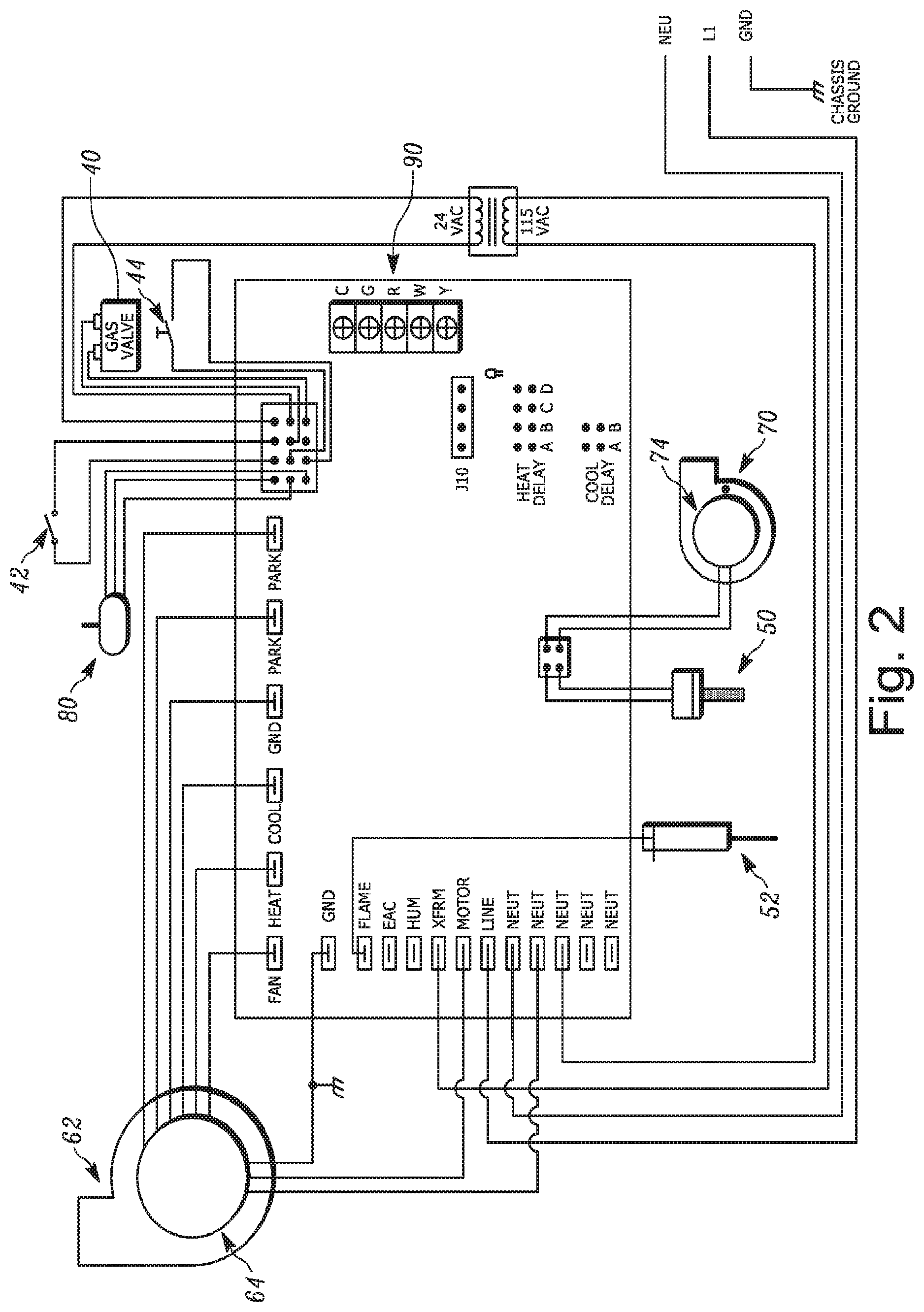
[0016] FIG. 2 is another schematic illustration of the control system of FIG. 1.
[0017] FIG. 3 is a front view of a burner in accordance with an embodiment of the present invention;
[0018] FIG. 4 is a front view of a distributor for producing multiple flame outputs for the burner of FIG. 1;
[0019] FIG. 5 an exploded view of a furnace constructed in accordance with one embodiment of the invention;
[0020] FIG. 6 is a side view of the furnace of FIG. 5 with the side panel removed;
[0021] FIG. 7 is an isometric view of cabinet portions of the furnace shown in FIG. 5; and
[0022] FIG. 8 is an isometric view of an alternative burner in accordance with an aspect of the invention.
DETAILED DESCRIPTION
[0023] The present invention relates to a furnace controller and, more specifically, relates to a system for controlling mass flow and noise in a furnace having an inducer blower. The inducer blower runs at a reduced speed during the ignition cycle to control the air flow through the burner for a smooth, consistent light-off. The speed control can be achieved by wave-chopping the input voltage to the inducer blower motor while maintaining a target pressure feedback signal from a sensor. Once flame is established, the inducer speed is increased to deliver the proper amount of combustion air for the duration of the heating cycle. The inducer blower is therefore modulated to maintain a constant pressure setpoint, which relates closely to mass flow, as determined by the functional needs of the furnace.
[0024] FIGS. 1-2 illustrate a furnace 10 including an example control system 12 in accordance with the present invention. The control system 12 can be configured to operate with any furnaces having a capacity of from about 40,000-140,000 Btu/H. The control system 12 can be used with a natural gas furnace 10 or a liquid propane furnace. One example furnace 10 for use with the control system 12 is shown and described in U.S. Patent Publication No. 2015/0369495, filed Jul. 24, 2015, the entirety of which is incorporated by reference herein. The furnace 10 can be a mid- or high efficiency residential furnace.
[0025] The furnace 10 includes a pre-mix burner 20, e.g., an ULN, pre-mix burner. The burner 20 is considered pre-mix because the combustion air and fuel are pre-mixed upstream of the burner. To this end, an air supply (shown schematically at 30) provides air from outside the furnace to a mixer 34. A single stage gas valve 40 supplies fuel, e.g., gas, to the mixer 34 at a constant flow rate. Alternatively, the gas valve 40 can be a modulating or multi-stage gas valve (not shown). The choice in gas valves 40 can be dictated by the type of furnace 10. For example, a single stage gas valve 40 can be used for the basic, most economical furnace. A two stage or modulating gas valve 40 can be used for more costly, feature-rich furnaces. Limit switches 42, 44 are provided in series with the gas valve 40 and close the gas valve in response to the supply air exceeding a prescribed temperature a predetermined number of times.
[0026] The mixer 34 delivers the pre-mixed air/fuel mixture to the burner 20, where it is ignited by an igniter 50. The igniter 50 can be a hot surface igniter that changes temperature based on the voltage, e.g., about 0 to 120VAC, applied thereto. A flame sensor 52 is used as a flame-proving device.
[0027] Once the pre-mixed mixture is ignited, heated combustion products exit the burner 20 and flow into a heat exchanger 60. The heat exchanger 60 can include a series of serpentine tubes with indentations or dimples along their lengths (not shown). A blower 62 blows air across the heat exchanger 60 such that the high temperature combustion/flue products heat the blown air. The blower 62 is driven by a motor 64. The motor 64 can be a multi-speed, permanent split capacitor (PSC) motor. As shown, the motor 64 is a four speed PSC motor that runs at different spends depending on whether the blower 62 is providing heating or cooling.
[0028] An inducer blower 70 located downstream of the heat exchanger 60 and in fluid communication with the interior of the heat exchanger tubes draws in combustion products from the heat exchanger and delivers them to a vent 72 to be exhausted from the furnace 10. The inducer blower 70 can have a forward curved construction and is configured for variable capacity operation. To this end, the inducer blower 70 can driven by a motor 74, e.g., shaded pole PSC motor driven with a wave-chopped control signal.
[0029] In another example, the motor 74 can be an electronically commutated motor (ECM) driven through a serial communications bus or pulse width modulation (PWM) control signal. In another example, a mechanical damper (not shown) can be installed at the inlet or outlet of the inducer blower 70 to vary the flow therethrough. Alternatively, the motor 74 can be a variable speed motor (not shown).
[0030] A sensor 80 extends into the heat exchanger 60 and monitors the air pressure of a designated/predetermined control volume therein. The sensor 80 can be a mass flow sensor, pressure sensor, pressure transducer or other device capable of outputting a usable/useful signal indicative of conditions within the heat exchanger 60.
[0031] A controller 90 is connected to the blower motor 64, the gas valve 40, the inducer blower motor 74, and the sensor 80 for actively controlling one or more of the gas valve 40 and blowers 62, 70. The controller 90 has a circuit for receiving signals from the sensor 80 that can include a high frequency noise filter and an analog-to-digital converter (not shown). The controller 90 can be integrated into the main controller of the furnace 10 or be a stand-alone controller integrated into the furnace control via serial communications interface, digital or analog control signal.
[0032] In a normal operating cycle of the burner 20, the inducer blower 70 initially moves ambient air at about 25.degree. C. through the burner and heat exchanger 60 prior to the ignition process. Immediately after ignition, the inducer blower 70 transitions to moving a mixture of flue products of steadily increasing temperature through the burner 20 and heat exchanger 60. Finally, during a steady-state operating period of the burner 20, the inducer blower 70 will move a steady flow of flue products in excess of 120.degree. C. through the burner 20 and heat exchanger 60.
[0033] The inducer blower 70 is a constant volume device. Consequently, the mass flow variations of the combustion air coming into the burner 20 due to the changing temperature and composition of the flue gases at the inducer blower 70 can be significant. Potential issues that result from such mass flow variations range from noisy ignitions, failed ignitions, unstable burner operation resulting in continued noisy operation, and/or failure to meet the required combustion performance levels (high NO.sub.x).
[0034] To combat these issues, the control system 12 utilizes the controller 90 to adjust the inducer blower 70 speed in response to changing system parameters/conditions. To this end, the sensor 80 sends a signal to the controller 90 indicative of the magnitude and direction of the parameter changes. In particular, the sensor 80 continuously measures a pressure drop across the control volume of the heat exchanger 60 and delivers a proportional signal to the controller 90 based on the measured pressure drop. The pressure drop is indicative of the mass flow of air and/or flue products through the control volume in the heat exchanger 60. The sensor 80 continuously sends signals to the controller 90 which, in response thereto, varies the speed of the inducer blower 70 to stabilize the combustion process and thereby meet desired performance results.
[0035] Instead of using a traditional variable speed motor to control the inducer blower 70, the controller 90 of the present invention instead relies on a single speed motor 74 and can use wave chopping to vary the speed thereof. In one example, the motor 74 speed is controlled with a zero-cross wave chopping circuit on the controller 90. Regardless of the wave-chopping method used, the controller 90 cooperates with the sensor 80 to form a pressure feedback control loop in order to maintain the motor 74 at a desired speed. As a result, the desired mass flow rate through the burner 20 and heat exchanger 60 can be maintained for a particular operating condition. The feedback loop also makes the control system 12 self-adapting to varying field conditions, such as the vent 72 length/configuration or vent system blockage, to maintain the target mass flow rate regardless of these or any other variations.
[0036] The control system 12 is an integrated furnace control which integrates the operation of all functions desirable to operate the furnace 10. These functions include, but are not limited to, sequencing; ignition control; safety functions; control of the gas valve, inducer motor, and blower motor. With this in mind, in the development/calibration process of the furnace 10, the pressure drop through the heat exchanger 60 control volume detected by the sensor 80 is mapped to the mass flow of the air and/or flue products flowing through the system. This signal naturally compensates for temperature variations and composition flowing through the heat exchanger 60. Also, the optimum combustion air flow for consistent, quiet light-off of the pre-mixed burner 20 is identified empirically, recorded, and stored in flash memory of the control system 12 for future use. This light-off setting may or may not provide the same stoichiometric mixture used for steady-state operation, as the burner 20 may prefer a richer or leaner mixture for the most robust light-off.
[0037] In the same way, the optimum steady-state operating condition is noted for stable operation and desired combustion performance once the burner 20 has been ignited and sufficiently warmed for continuous operation. All of these parameters, along with related timings, are recorded and stored in the non-volatile memory of a microprocessor in the control system 12.
[0038] In the case of a single-stage furnace, the gas valve 40 is either energized or de-energized, and supplies a constant heat input to the heat exchanger 60 when energized. During development, the inducer blower 70 timing settings for pre-purge, post-purge, and warm-up cycles of the furnace 10 are also defined based on desired pressure settings within the heat exchanger 60 according to the table below. The actual settings can be in accordance with ANSI standard Z21.20, another ANSI standard or have non-ANSI standard values.
TABLE-US-00001 Pressure Setting Time State (in.w.c.) (examples in seconds) Pre-purge P1 T1 (1.0) Ignitor Warm-up P2 T2 Ignition P3 T3 Flame Stabilization Period P4 T4 (.45) Run P5 Until heating call is satisfied (1.0) Post-purge P6 T6 (1.0) Inter-Purge P7 T7 (1.0)
[0039] In this example, when the furnace 10 receives a call for heat, typically from a thermostat 76 in the living space, the controller 90 energizes the inducer blower 70 for the pre-purge cycle and selects the blower speed such that the sensor 80 returns a signal correlating to the system pressure drop of P1. The inducer blower 70 is maintained in this state for duration T1. The pre-purge cycle is intended to allow for the dissipation of any unburned gas or residual products of combustion at the beginning of the furnace 10 operating cycle prior to initiating ignition.
[0040] After the pre-purge time T1, the controller 90 energizes the igniter 50 for a warm-up period and adjusts the inducer blower 70 speed such that the sensor 80 returns a signal correlating to the system pressure drop of P2. The igniter 50 is warmed up prior to initiating gas flow, and includes both a period of time in which the voltage to the igniter is ramped from 0 to 120 VAC and a period of time in which the voltage is maintained at a constant 120 VAC.
[0041] Once the igniter 50 is sufficiently heated, the controller 90 adjusts the inducer blower 70 to reach a sensor 80 feedback of P3. When this occurs, the controller 90 opens the gas valve 40 for duration T3 to allow the pre-mixed mixture to flow from the mixer 34 to the burner 20. Since the igniter 50 is already sufficiently heated, the flowing pre-mixed mixture is ignited by the igniter. The flame sensor 52 sends a signal to the controller 90 to confirm successful ignition. The period of time allowed for the ignition of the main burners in the burner 20 [during which the igniter 50 is energized and the gas valve 40 open] is known as the trial for ignition, and is built into the time T2 and/or T3.
[0042] The inducer blower 70 is adjusted again to achieve a sensor 80 pressure of P4 and maintained for duration T4 to stabilize the flame. The flame stabilization period T4 is the time permitted, after successful ignition, for the main burner flame to stabilize before entering the "Run" state.
[0043] It should be noted that during operation of the burner 20 from this point forward, the temperature will vary at the induced draft blower 70, which would normally cause unacceptable fluctuations in the mass flow through the burner 20. Due to the control system 12, however, the sensor 80 detects these variances as increased or decreased pressure drop across the control volume and reports these variations to the controller 90. In response, the controller 90 increases or decreases the inducer blower 70 speed to maintain a constant pressure drop reading at the sensor 80. It is this response that allows the system 12 to maintain the desired mass flow through the burner 20.
[0044] At this point in the process, a stable flame is established on the surface of the burner 20 and the system is set to the "Run" pressure setting P5 for the duration of the heating cycle. Once the thermostat 76 is satisfied and the call for heat is removed by the controller 90, the gas valve 40 is de-energized, the inducer blower 70 is adjusted to achieve a sensor 80 pressure of P6, and the post-purge cycle is continued for duration T6. The post-purge cycle allows for the dissipation of any unburned or residual products of combustion at the end of the furnace burner operating cycle. Post-purge begins when the flame sensor 52 determines there is no flame at the burner 20 surface.
[0045] It should be noted that the trial for ignition can fail periodically. When this occurs, inter-purge step is performed for duration T7 to allow for the dissipation of any unburned gas or residual products of combustion between the failed trial for ignition and the retry period. The inter-purge is performed while the sensor 80 indicates a pressure P7.
[0046] In another example operation of the furnace 12, once a call for heat from the thermostat 76 is indicated at the controller 90, the inducer blower 70 is energized and controlled to a pre-determined pressure output for a predetermined time to achieve a pre-purge of the combustion chamber/heat exchanger 60. The igniter 50 is then energized.
[0047] The inducer blower 70 is then set to a new pressure setting for the ignition process. This inducer blower 70 setting purposely operates at a setting calculated to operate the burner 20 at a different air/fuel ratio than the normal target. Typically, the burner 20 is lit off at a rich ratio (less combustion air) but at full rate (single stage gas valve) to achieve an acceptably quiet light-off.
[0048] Once the flame is established and proved by the flame sensor 52, a flame stabilization mode is initiated at which the inducer blower 70 is operated at a designated pressure for a pre-determined time to stabilize the flame and warm up the burner 20 and heat exchanger 60. This operating point also runs a rich air/fuel ratio and serves to get the flue gas temperatures closer to the normal operating temperatures, which brings the flue gas density closer to normal.
[0049] After the flame stabilization period, the inducer blower 70 is ramped up to the normal operating pressure and the system enters the "Run" mode. The flame has been stabilized by this time by warming up the burner 20 media, warming up the heat exchanger 60, and raising the temperature of the flue products to a "normal" temperature. This stabilizes the density such that the mass flow is nearly constant for stable burner 20 operation and targeted combustion efficiencies.
[0050] The control system 12 of the present invention is advantageous in that a predetermined combustion air flow across the igniter 50 is achieved during igniter warm-up, which ensures the desired ignition temperature can be achieved. This might be considerably less than other operating states. Furthermore, corrections can be made to the air/fuel ratio flowing through the burner 20 during light-off, which ensures a stable, quiet ignition. To this end, pre-mixed burners operate better when lit in a slightly rich environment.
[0051] Additionally, combustion air can selectively flow during the flame stabilization period, again possibly slightly rich, to allow the flame to stabilize prior to steady state operation. A consistent air/fuel ratio can be achieved during the "Run" cycle of the furnace to optimize the combustion process for compliance with ULN regulations and codes. Since the control system of the present invention does not simultaneously vary the fuel and combustion air the control hardware and software algorithms can be simplified, thereby making the control system less expensive and the sequence of operation less complication.
[0052] This description mentions only variations in flue gas temperature and composition as possible causes for mass flow changes in the appliance. It will be appreciated, however, that once installed in the field, there are a number of other factors that can cause the mass flow of the system to shift, thereby resulting in noisy operation or poor combustion performance, e.g., venting configurations--direct vs. non-direct vent applications, venting length, excessive wind applied to the vent terminations, altitude, and venting system blockages, such as ice or debris. The control system 12 can include additional sensors and/or furnace 10 components that can be monitored/controlled by the controller 90 to maintain the desired mass flow rate in view of these additional factors. In any case, the mass flow rate is controlled for each operating stage of the furnace to help maintain flame stability and combustion quality.
[0053] The control system of the present invention is also advantageous in its ability to reduce noise in the furnace. Instead of the aforementioned "soft start" strategy, the control system of the present invention specifically tailors the system pressure to reduce undesirable furnace noise. More specifically, during the development/calibration process, tests are conducted to identify the harmonic resonance operating conditions for the specific furnace being used. Once these operating points are identified, the combustion air pressure settings used during the light-off, flame stabilization, and run modes indicated above are selected to avoid operating the pre-mixed burner and heat exchanger in these specific resonance operating points. In this way, desirable furnace operating conditions in combustion performance, quiet operation, and stable burner control are achieved.
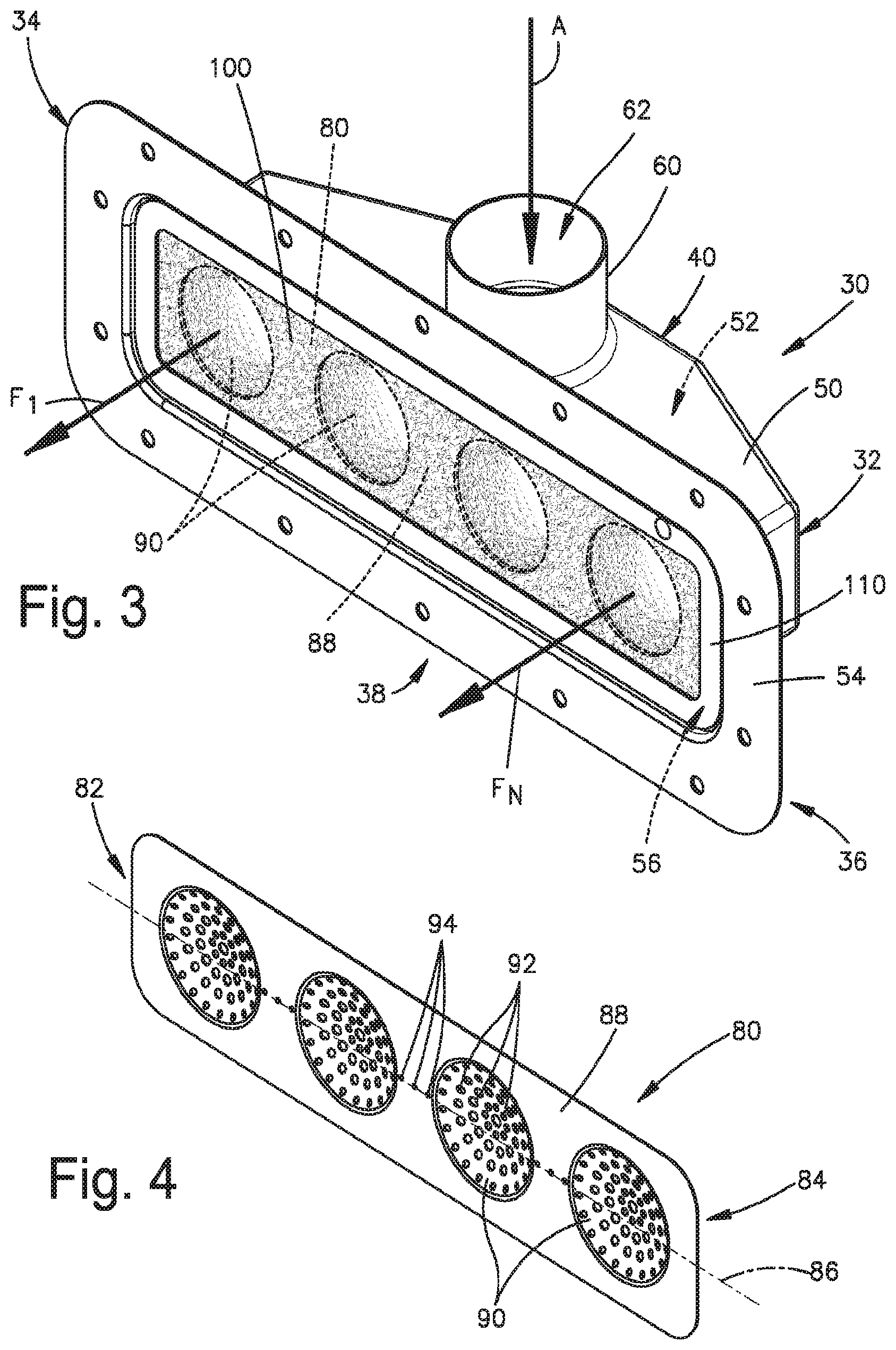
[0054] FIGS. 3-5 illustrate a burner 30 in accordance with an aspect of the present invention. The burner 30 includes a body 32 that extends from a first end 34 to a second end 36. The body 32 is formed from a durable material such as metal and has a first or front side 38 and a second or rear side 40 opposite the front side. The body 32 is formed by a sidewall 50 that has an elongated shape such as, for example, rectangular or trapezoidal. The sidewall 50 defines an interior chamber 52 that receives a pre-mixed mixture of fuel and air. In particular, an inlet conduit 60 in fluid communication with the interior chamber 52 extends from the sidewall 50 and includes an opening 62 connected to a fuel and air mixer (not shown) in order to supply the pre-mix mixture to the interior chamber.
[0055] A flange 54 extends from the sidewall 50 along the front side 38 of the body 32. The flange 54 has a rectangular shape and includes an opening 56 in fluid communication with the interior chamber 52. The opening 56 in the flange 54 receives a distributor 80 (FIG. 4). The distributor 80 closes the opening 56 in the flange 54 and substantially seals the front side 38 of the body 32. The distributor 80 has an elongated shape that mimics the shape of the opening 56 in the flange 54, e.g., rectangular. The distributor 80 extends along a centerline 86 from a first end 82 to a second end 84. When the distributor 80 is secured to the flange 54 (see FIG. 3) the first end 82 of the distributor is positioned at the first end 34 of the body 32 and the second end 84 is positioned at the second end 36 of the body.
[0056] Referring to FIG. 4, the distributor 80 is formed from a thin, durable, and heat-resistant material such as metal, metal screen or expanded metal. The distributor 80 includes a first portion 88 and at least one dimple or second portion 90 formed or provided on the first portion. The number, size, and spacing of the second portions 90 coincides with the number, size, and spacing of downstream heat exchanger sections (not shown) in the furnace in which the burner 30 is used. In particular, each second portion 90 is aligned with an open end of an associated heat exchanger section such that the end of each section is in fluid communication with each second portion.
[0057] In one example, the first portion 88 has a planar configuration and each second portion 90 is curved or dimple-shaped, e.g., rounded, hemispherical, circular, concave or convex. Every second portion 90 may have the same configuration or different configurations from one another. A concave second portion 90 will provide a narrow, long or elongated flame while a convex second portion will provide a wider, more dispersed flame. Each second portion 90 may exhibit any circular or polygonal shape such as triangular, square or the like. The planar portion 88 extends substantially along the centerline 86.
[0058] Perforations 92 formed in each concave portion 90 extend entirely through the distributor 80. The perforations 92 may exhibit any shape and may be randomly spaced about the concave portion 90 or may have predetermined spacing. The perforations 92 cooperate with the concave portions 90 to produce an elongated flame for each concave portion that extends into the corresponding heat exchanger section (not shown) during use of the burner 30.
[0059] Carryover perforations 94 may also extend through the planar portion 88 of the distributor 80. The carryover perforations 94 may be similar, identical or different than the perforations 92 in the concave portions 90. The carryover perforations 94 cooperate with the perforations 92 to provide a flame path between adjacent concave portions 90. The path allows a flame initiated at one concave portion 90 to propagate to all the concave portions 90 in the distributor 80.
[0060] a. An axis (not shown) extends perpendicular to the planar portion 88 and through the center of a concave portion 90. The perforations 94 extend substantially parallel to the axis and the perforations 92 are angled towards the axis. Consequently, flow through the perforations 92 of each concave portion 90 is directed towards a common point along the axis that coincides with the center of that curved portion. This helps to focus the flame produced therefrom along the axis towards the center of the respective heat exchanger section (not shown). Flow through the perforations 94, however, is directed in a direction substantially parallel to the axis.
[0061] A fiber mesh burner surface 100 overlies the distributor 80 and is formed from a material such as an iron-chromium alloy, e.g., FeCrAlM. The burner surface 100 is contoured to match the contour of the distributor 80 and, thus, the burner surface includes the same dimples or rounded portion(s) as the distributor. A cover retainer 110 is secured to the flange 54 of the body 32 to secure the fiber mesh burner surface 100 and distributor 80 between the body and the cover retainer.
[0062] In operation, and referring to FIG. 3, a 100% pre-mix mixture of air and fuel is supplied via a mixer, duct or the like (not shown) upstream of the burner 30 to the opening 62 of the inlet conduit 60 in the manner indicated generally by the arrow A. The pre-mix mixture flows through the interior chamber 52 and towards the opening 56 in the flange 54. The pre-mix mixture then flows through the perforations 92, 94 in both the concave portions 90 and the planar portion 88 of the distributor. When activated, an igniter (not shown) positioned adjacent to the leftmost concave portion 90 (as viewed in FIG. 3) ignites the pre-mix mixture flowing through the leftmost concave portion. The air and fuel mixture is ignited to produce a flame, indicated generally by arrow F.sub.1 in FIG. 1 that extends from the surface of the fiber mesh burner surface 100 outward away from the burner 30 into the associated heat exchanger section (not shown).
[0063] The flame F.sub.1 in the leftmost concave portion 90 carries over or propagates across the planar portion 88 via the carryover perforations 94 and ignites the pre-mix mixture flowing through each successive concave portion until a flame F.sub.n is produced in the rightmost concave portion of the distributor 80 (as viewed in FIG. 3). This directs the flame F.sub.n into the corresponding heat exchanger section in the furnace (not shown). A flame sensor (not shown) may be positioned adjacent to the rightmost concave portion 90 that produces the flame F.sub.n in order to provide proof of ignition and propagation.
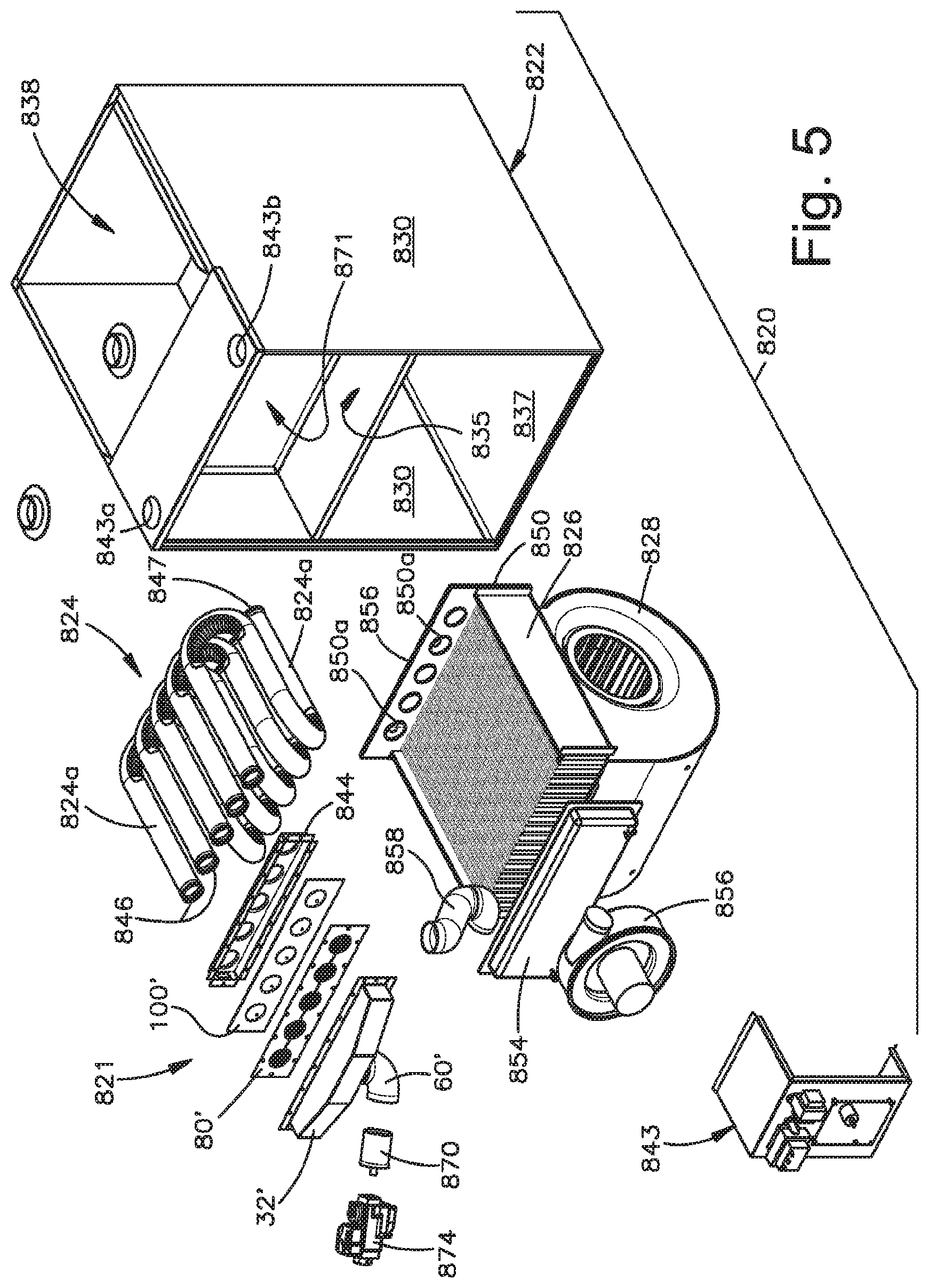
[0064] FIGS. 5-7 illustrate a furnace 820 that includes a furnace cabinet housing and supporting a burner assembly 821 similar to the burner 30, along with peripheral components, including heat exchangers, blowers, etc. The furnace 820 includes a furnace cabinet 822, a primary heat exchanger 824 that comprises a plurality of serpentine tubes 824a, a secondary. condensing heat exchanger 826, and a circulating air blower 828. Alternatively, the primary heat exchanger 824 may have a clamshell design known in the art. Components of the burner assembly 821 that are similar to the components of the burner 30 are given the same reference numeral with the added suffix "'".
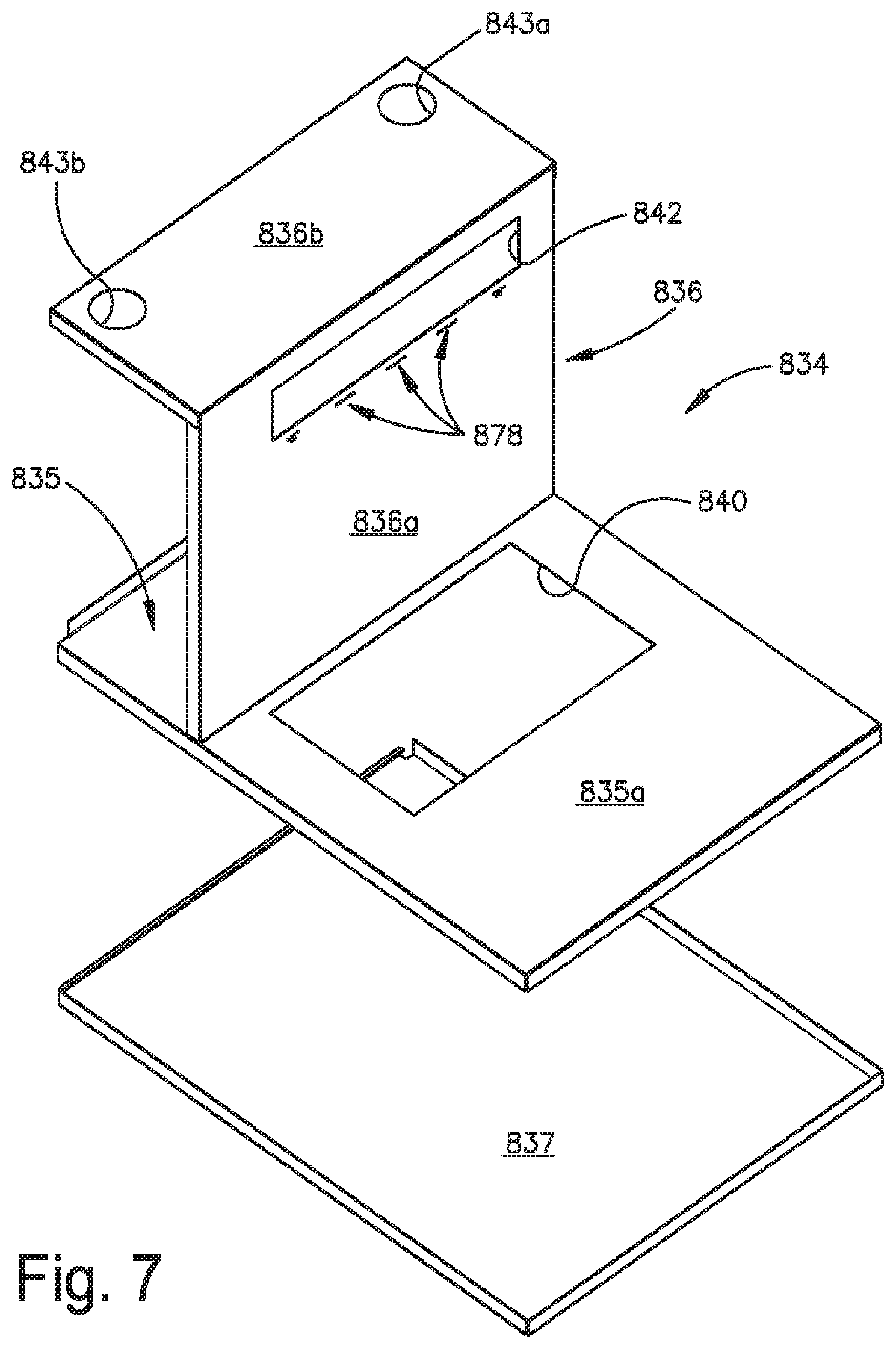
[0065] The furnace cabinet includes a pair of vertical side panels 830 and a vertical rear panel 832. An intermediate plate assembly 834 is supported between the side panels 830 and the rear panel 832 and includes a blower deck plate 835 and an inverted L-shaped support plate 836. A vertical section 836a of the L-shaped support plate 836 forms a vest panel which, as will be explained, supports the burner 821. A horizontal segment 835a of the blower deck plate 835 and portions of the side panel 830 and rear panel 832 define a heat exchange chamber 838 (best shown in FIG. 5). The furnace 820 also includes a base 837 that cooperates with the horizontal segment 835a and portions of the side panel 830 and rear panel 832 to define a blower chamber for receiving the blower 828.
[0066] The secondary heat exchanger 826 (FIG. 5) sits atop and is supported by the deck plate segment 835a and overlies a rectangular opening 840. The blower 828 is supported below the deck plate 835 and includes a rectangular exit (not shown) aligned with the deck plate opening 840. Air discharged by the blower 828 enters the heat exchange chamber 838 through the opening 840. A control panel 843 is attached to the blower 828 and/or the blower deck plate 835 and mounts conventional controls for the blower 828 and burner assembly 821.
[0067] The burner assembly 821 is attached to the vest panel 836a and is received in a rectangular opening 842 (FIG. 7) defined in the vest panel 836a of the plate 836. In particular, the burner body 32' is shaped and sized to conform to the rectangular opening 842 in the vest panel 836a. The burner body 32' includes tapered end sections which operate to provide a more even flow of gas/air mixture to the distributor 80'. The burner body 32' is suitably attached to the exterior side of the vest panel 836a and includes a fuel/air inlet 60'. The distributor 80' that defines the perforated portions 90' is clamped between the body 32' and the exterior of the vest panel 836a. A combustion chamber defining cover 844 is attached to the interior side of the vest panel 836a in alignment with the burner body 32'. The component 100' defining the burner surface (which may be the previously disclosed fiber mesh burner surface 100) is supported between the distributor 80' and the interior of the combustion chamber cover 844. The component 100' may be formed by, for example, sintering, weaving and/or knitting techniques.
[0068] The combustion chamber cover 844 includes a plurality of openings 844a each aligned with one of the burner portions 90' defined in the distributor 80'. The openings 844a each receive an associated inlet side 846 of an associated heat exchange section 824a (FIG. 5). It should be apparent that the portions 90' are therefore aligned with associated heat exchange sections 824a. The inlet sides 846 of the heat exchange sections 824a may be attached to the combustion chamber cover 844 by means of a known swaging process. The flame F of each portion 90' extends through the associated opening 844a of the cover 844 and into the inlet side 846 of the associated heat exchange section 824a. The flames F are tailored such that the tip of each flame terminates at or adjacent to the inlet side 846 of each section 824a, i.e., the flames may barely extend into the interior of each tube.
[0069] As best seen in FIG. 5, discharge ends 847 of each heat exchange section 824a are connected (as by swaging) to an intermediate collector box 850 having associated ports 850a. The intermediate collector box 850 receives the hot exhaust gasses from the heat exchange sections 824a and causes the exhaust gas to pass through the secondary heat exchanger 826. After passing through the secondary heat exchanger 826, the exhaust gasses are received and collected in a collector chamber 854 which communicates with an induced draft blower or inducer blower 856. The exhaust gasses are drawn out by the induced draft blower 856 and are discharged to an outlet conduit 858 to be vented.
[0070] Referring to FIG. 6, the furnace cabinet 822 includes conduit ports 843a, 843b. The conduit port 843a receives a combustion air conduit (not shown) that provides a source of combustion air which is delivered to the vestibule 871 and, thus, is delivered to the mixer 870. The port 843b receives the exhaust conduit 858 or vent (not shown) through which the products of combustion are exhausted to the outside.
[0071] As best seen in FIGS. 6-7, the blower opening 840 in the blower deck plate 835 is located near the inlet side 846 of the heat exchange sections 824a and, thus, air to be heated is discharged near the burner side of the heat exchange chamber 838, i.e., near the vest panel 836a. In conventional furnaces, the flames extend deep into the heat exchange tubes and therefore the blower--and associated blower opening--is located further down the length of the tubes from the burner side. Since the flames from the burner assembly 821, 821', 821'' terminate at or adjacent to the openings in the heat exchange sections 824a the blower opening 840 and blower 828 can be aligned with the inlets to the heat exchange sections on a side of the vest panel 836 opposite to the burner assembly, i.e., within the heat exchange chamber 838. Air from the blower 828 therefore washes over the heat exchange sections 824a where the flames are the hottest.
[0072] FIG. 8 illustrates portions of another burner 930 in which the distributor and fiber mesh are omitted for brevity and clarity. In FIG. 8, features that are similar to those in FIGS. 3-4 have a reference numeral that is 900 greater than the reference numerals in FIGS. 1-3. In FIG. 8, the burner 930 is configured such that the igniter 911 and flame sensor 913 are positioned outside the heat exchanger compartment 838 and within the vestibule 871. More specifically, the burner 930 includes a body 932 having a substantially trapezoidal sidewall 950 that defines an interior chamber 952. The sidewall 950 includes an extension 953 that extends along the front side 938 of the body 932. The vest panel 836' includes a series of bends 839 that form a notch which defines a passage 841 extending along and above the extension 953 for receiving the extension. The bends 839 position the extension 953 outside of the heat exchanger compartment 838 and the passage 841 is sized to allow the igniter 911 and flame sensor 913 to be inserted through the extension 953 into the interior 952 of the body 932.
[0073] A viewing window 915 formed in the extension 953 allows for visual inspection of the interior chamber 952. A series of pressure relief sections constituting openings 917 may be formed along the extension 953 for mitigating pulsing and resonance within the interior chamber 952. It is believed that these openings 917 may allow secondary air to flow into the combustion chamber during operation of the burner assembly 930.
[0074] The combustion chamber cover 944 is attached to the interior or heat exchanger compartment 838 side of the vest panel 836a'. The combustion chamber cover 944 includes an interior space 946 and a plurality of openings 944a each aligned with one of the burner portions (not shown) defined in the distributor (not shown). The openings 944a each receive an associated inlet side 846 of an associated heat exchange section 824a (FIG. 5) to align the burner portions with associated heat exchange sections 824a. The inlet sides 846 of the heat exchange sections 824a may be attached to the combustion chamber cover 944 by means of a known swaging process. The flame of each burner portion extends through the associated opening 944a of the cover 944 and into the inlet side 846 of the associated heat exchange section 824a. Both the igniter 911 and the flame sensor 913 may extend through the combustion chamber cover 944 to the interior space 946 within the heat exchange chamber 838.
[0075] The burner has been described in connection with a condensing type furnace. It should be noted that the burner of the present invention can be used in a non-condensing type furnace.
[0076] What have been described above are examples of the present invention. It is, of course, not possible to describe every conceivable combination of components or methodologies for purposes of describing the present invention, but one of ordinary skill in the art will recognize that many further combinations and permutations of the present invention are possible. Accordingly, the present invention is intended to embrace all such alterations, modifications and variations that fall within the spirit and scope of the appended claims.
* * * * *
D00000
D00001
D00002
D00003
D00004
D00005
D00006
D00007
XML
uspto.report is an independent third-party trademark research tool that is not affiliated, endorsed, or sponsored by the United States Patent and Trademark Office (USPTO) or any other governmental organization. The information provided by uspto.report is based on publicly available data at the time of writing and is intended for informational purposes only.
While we strive to provide accurate and up-to-date information, we do not guarantee the accuracy, completeness, reliability, or suitability of the information displayed on this site. The use of this site is at your own risk. Any reliance you place on such information is therefore strictly at your own risk.
All official trademark data, including owner information, should be verified by visiting the official USPTO website at www.uspto.gov. This site is not intended to replace professional legal advice and should not be used as a substitute for consulting with a legal professional who is knowledgeable about trademark law.