Pump Apparatus
KOBAYASHI; Yoshiyuki ; et al.
U.S. patent application number 16/484970 was filed with the patent office on 2019-12-19 for pump apparatus. The applicant listed for this patent is Nidec Tosok Corporation. Invention is credited to Koji HIGUCHI, Kazuhiro HOMMA, Yosuke ITO, Yoshiyuki KOBAYASHI.
| Application Number | 20190383291 16/484970 |
| Document ID | / |
| Family ID | 63370487 |
| Filed Date | 2019-12-19 |


| United States Patent Application | 20190383291 |
| Kind Code | A1 |
| KOBAYASHI; Yoshiyuki ; et al. | December 19, 2019 |
PUMP APPARATUS
Abstract
A pump apparatus includes a motor including a shaft rotatable around a central axis, and a pump that is positioned on one side in an axial direction thereof, is driven via the shaft, and discharges an oil. The motor includes a rotor, a stator, a housing accommodating the rotor and the stator, a wall partitioning the stator and the rotor, and a motor side discharge port to discharge an oil. The pump includes a pump rotor, a pump case accommodating the pump rotor, a pump side suction port to suction an oil, and a pump side delivery port to deliver an oil to the inside of the motor. A pump apparatus includes a first flow channel to cause an oil to flow into the pump through a pump side suction port, a second flow channel to cause an oil to flow to a stator region through the pump side delivery port, and a third flow channel to cause an oil to flow into the stator.
| Inventors: | KOBAYASHI; Yoshiyuki; (Zama-shi, JP) ; HOMMA; Kazuhiro; (Zama-shi, JP) ; HIGUCHI; Koji; (Zama-shi, JP) ; ITO; Yosuke; (Zama-shi, JP) | ||||||||||
| Applicant: |
|
||||||||||
|---|---|---|---|---|---|---|---|---|---|---|---|
| Family ID: | 63370487 | ||||||||||
| Appl. No.: | 16/484970 | ||||||||||
| Filed: | February 23, 2018 | ||||||||||
| PCT Filed: | February 23, 2018 | ||||||||||
| PCT NO: | PCT/JP2018/006641 | ||||||||||
| 371 Date: | August 9, 2019 |
| Current U.S. Class: | 1/1 |
| Current CPC Class: | F04C 2/18 20130101; H02K 7/14 20130101; F04C 15/0096 20130101; F04C 29/042 20130101; F04C 2210/206 20130101; F04C 11/008 20130101; F04C 2/102 20130101; F04C 2240/20 20130101; H02K 9/19 20130101; F04C 15/008 20130101; F04C 2240/30 20130101; F04C 2240/40 20130101; F04C 2240/60 20130101 |
| International Class: | F04C 29/04 20060101 F04C029/04 |
Foreign Application Data
| Date | Code | Application Number |
|---|---|---|
| Mar 3, 2017 | JP | 2017-040767 |
Claims
1-14. (canceled)
15. A pump apparatus comprising: a motor including a shaft rotatably supported about a central axis extending in an axial direction; and a pump that is positioned on one side of the motor in the axial direction, is driven by the motor via the shaft, and discharges an oil; wherein the motor includes: a rotor rotatable around the shaft; a stator disposed on an outer side of the rotor in a radial direction; a housing accommodating the rotor and the stator; a wall provided between an inner circumference of the stator and an outer circumference of the rotor to partition the stator and the rotor from each other; and a motor side discharge port to discharge the oil inside the motor; the pump includes: a pump rotor attached to the shaft; a pump case accommodating the pump rotor; a pump side suction port to suction the oil into the pump using a negative pressure in the pump; and a pump side delivery port to deliver the oil inside the pump to the inside of the motor using pressurization of the pump; and the pump apparatus further comprises: a first flow channel to cause the oil to flow into the pump through the pump side suction port; a second flow channel to cause the oil to flow to a region on a side which is partitioned by the wall and on which the stator is present inside the motor, through the pump side delivery port; and a third flow channel provided inside the stator to cause the oil to flow into the stator.
16. A pump apparatus comprising: a motor including a shaft rotatably supported about a central axis extending in an axial direction; and a pump that is positioned on one side of the motor in the axial direction, is driven by the motor via the shaft, and discharges an oil; wherein the motor includes: a rotor rotatable around the shaft; a stator disposed on an outer side of the rotor in a radial direction; a housing accommodating the rotor and the stator; a wall provided between an inner circumference of the stator and an outer circumference of the rotor to partition the stator and the rotor from each other; and a motor side suction port to suction the oil into the motor between the housing and the wall; the pump includes: a pump rotor attached to the shaft; a pump case accommodating the pump rotor; and a pump side introduction port to introduce the oil inside the motor into the pump using a negative pressure in the pump; and the pump apparatus includes: a fourth flow channel to cause the oil to flow into the motor through the motor side suction port; a third flow channel provided inside the stator to cause the oil to flow into the stator; and a fifth flow channel to introduce the oil inside the motor into the pump through the pump side introduction port.
17. The pump apparatus according to claim 15, wherein the stator includes: a cylindrical core back portion provided to surround the central axis; a plurality of teeth portions provided at predetermined intervals in a circumferential direction to protrude to the rotor side from an inner surface of the core back portion; and a coil wound around the teeth portion; wherein the third flow channel is provided between the coils respectively wound around a pair of teeth portions adjacent to each other in the circumferential direction.
18. The pump apparatus according to claim 17, further comprising: a sixth flow channel to cause the oil to flow between the core back portion and the housing.
19. The pump apparatus according to claim 17, wherein the coil is resin-molded.
20. The pump apparatus according to claim 15, wherein the wall includes a cylinder portion covering an outer circumferential surface of the rotor and extending in the axial direction of the shaft.
21. The pump apparatus according to claim 20, wherein in the cylinder portion, a first end portion of the cylinder portion in the axial direction comes into contact with the pump case and a second end portion of the cylinder portion in the axial direction comes into contact with a second end portion of the housing in the axial direction.
22. The pump apparatus according to claim 17, wherein the wall and the stator are integrally molded structures made of a resin.
23. The pump apparatus according to claim 21, wherein the cylinder portion comes into contact with the pump case via a seal.
24. The pump apparatus according to claim 23, wherein a recessed portion is provided in any one of contact portions of the cylinder portion and the pump case which come into contact with each other via the seal, and the seal is inserted into the recessed portion.
25. The pump apparatus according to claim 21, wherein the cylinder portion comes into contact with the second end portion of the housing of the motor in the axial direction via a seal.
26. The pump apparatus according to claim 25, wherein a recessed portion is provided in any one of contact portions of the cylinder portion and the second end portion of the housing in the axial direction which come into contact with each other via the seal, and the seal is inserted into the recessed portion.
27. The pump apparatus according to claim 15, wherein a space surrounded by the stator, the wall, and the housing to be able to be filled with the oil is provided between an end portion of the stator in the axial direction and an end portion of the housing in the axial direction inside the motor.
28. The pump apparatus according to claim 16, wherein a space surrounded by the stator, the wall, and the housing to be able to be filled with the oil is provided between an end portion of the stator in the axial direction and an end portion of the housing in the axial direction inside the motor.
Description
CROSS REFERENCE TO RELATED APPLICATIONS
[0001] This is a U.S. national stage of PCT Application No. PCT/JP2018/006641, filed on Feb. 23, 2018, and priority under 35 U.S.C. .sctn. 119(a) and 35 U.S.C. .sctn. 365(b) is claimed from Japanese Application No. 2017-040767, filed Mar. 3, 2017, the entire disclosures of each application are hereby incorporated herein by reference.
FIELD OF THE INVENTION
[0002] The present invention relates to a pump apparatus.
BACKGROUND
[0003] Recently, electric oil pumps used for transmissions and the like have been required to have responsiveness. In order to realize responsiveness in an electric oil pump, there is a need to increase the output of a motor for an electric oil pump. When a motor for an electric oil pump has a high output, a large current flows in a coil of the motor, so that the temperature of the motor becomes high, and a permanent magnet of the motor may be demagnetized, for example. Therefore, in order to curb a temperature rise in the motor, there is a need to provide a cooling structure in the motor. Japanese Patent Laid-open No. 2008-125235 discloses an electric motor including an oil supply mechanism in which a relative positional relationship between a stator and a rotor in an axial direction is displaced using an oil pressure of an oil according to a rotation speed of the rotor and the rotor is cooled by the oil.
[0004] However, the electric motor disclosed in Japanese Patent Laid-open No. 2008-125235(which will hereinafter be referred to as "the electric motor in the related art") has a structure in which a cooling flow channel switches between a low speed and a high speed, but this structure is complicated and it is difficult to be realized. In addition, in the electric motor in the related art, when an oil circulates inside a rotor, the inertia of the rotor increases, so that there is concern that the rotational efficiency of the rotor may be degraded. Moreover, in the electric motor in the related art, when an oil circulates between a stator and the rotor, there is concern that the rotational efficiency of the rotor may be degraded due to the viscosity of the oil.
SUMMARY
[0005] Example embodiments of the present disclosure provide pump apparatuses each of which has a structure that achieves a high cooling effect on a motor without degrading the rotational efficiency of a rotor.
[0006] According to an example embodiment of the present disclosure, a pump apparatus includes a motor including a shaft rotatably supported about a central axis extending in an axial direction, and a pump that is located on one side of the motor in the axial direction, is driven by the motor via the shaft, and discharges an oil. The motor includes a rotor rotatable around the shaft, a stator disposed on an outer side of the rotor in a radial direction, a housing accommodating the rotor and the stator, a wall provided between an inner circumference of the stator and an outer circumference of the rotor to partition the stator and the rotor from each other, and a motor side discharge port to discharge the oil inside the motor. The pump includes a pump rotor attached to the shaft, a pump case accommodating the pump rotor, a pump side suction port to suction the oil into the pump using a negative pressure in the pump, and a pump side delivery port to deliver the oil inside the pump to the inside of the motor using pressurization of the pump. The pump apparatus includes a first flow channel to cause the oil to flow into the pump through the pump side suction port, a second flow channel to cause the oil to flow to a region on a side that is partitioned by the wall and on which the stator is present inside the motor, through the pump side delivery port, and a third flow channel provided inside the stator to cause the oil to flow into the stator.
[0007] According to an example embodiment of the present disclosure, it is possible to provide a pump apparatus including a structure that achieves a high cooling effect on a motor without degrading a rotational efficiency of a rotor.
[0008] The above and other elements, features, steps, characteristics and advantages of the present disclosure will become more apparent from the following detailed description of the example embodiments with reference to the attached drawings.
BRIEF DESCRIPTION OF THE DRAWINGS
[0009] FIG. 1 is a cross-sectional view of a pump apparatus according to a first example embodiment of the present disclosure.
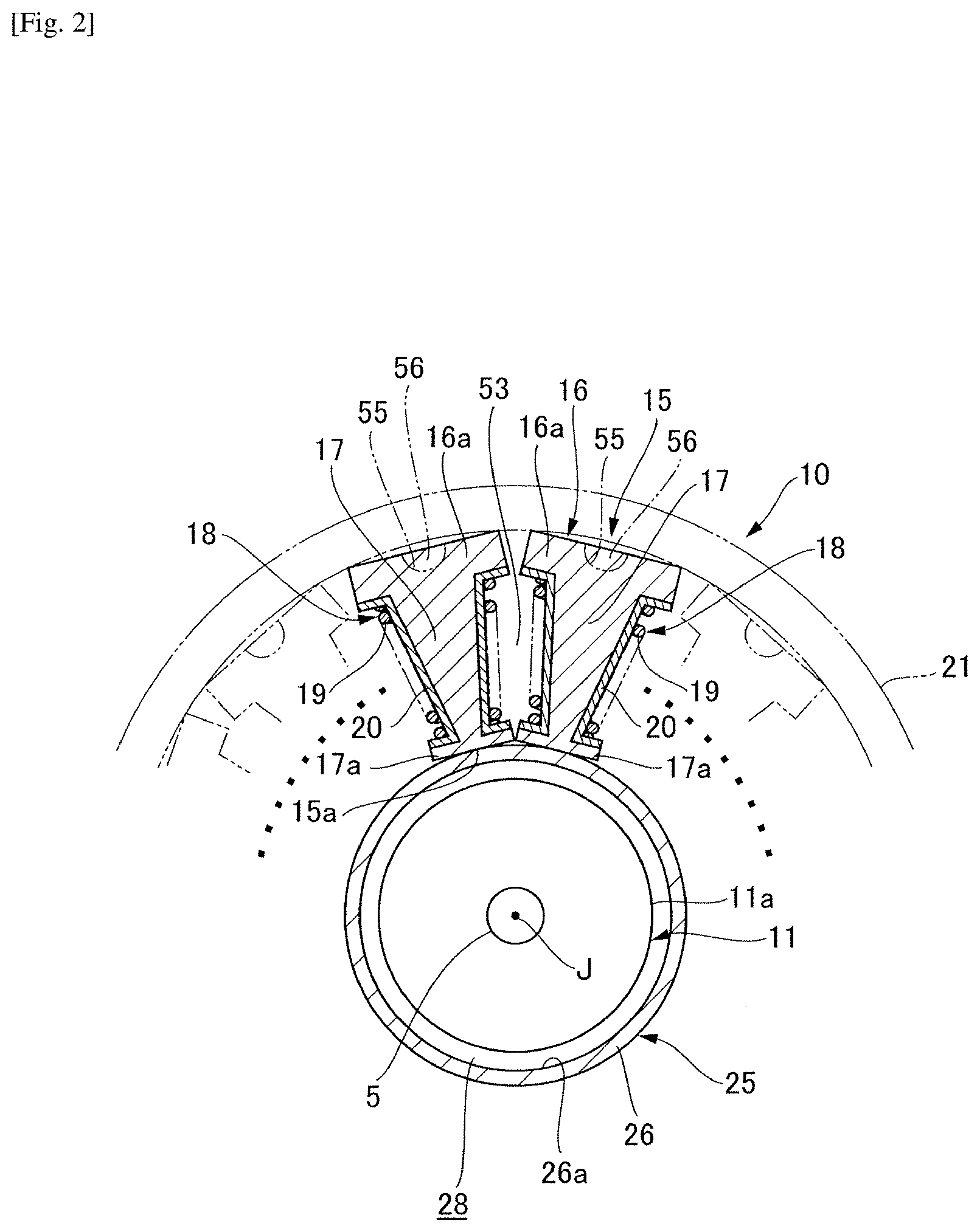
[0010] FIG. 2 is a cross-sectional view of a main portion of the pump apparatus corresponding to an arrow view taken along I-I in FIG. 1.
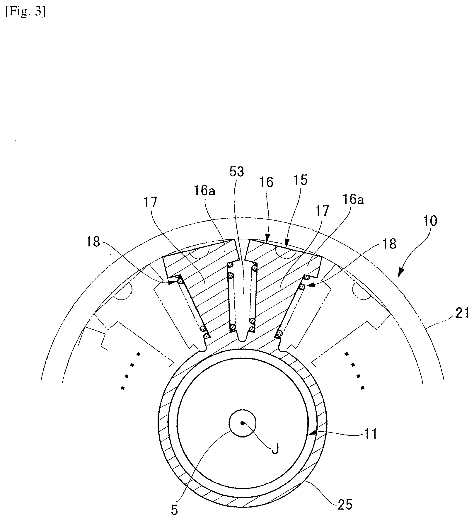
[0011] FIG. 3 is a cross-sectional view of the main portion of the pump apparatus in which a stator and a wall portion are provided as a portion of a single structure.
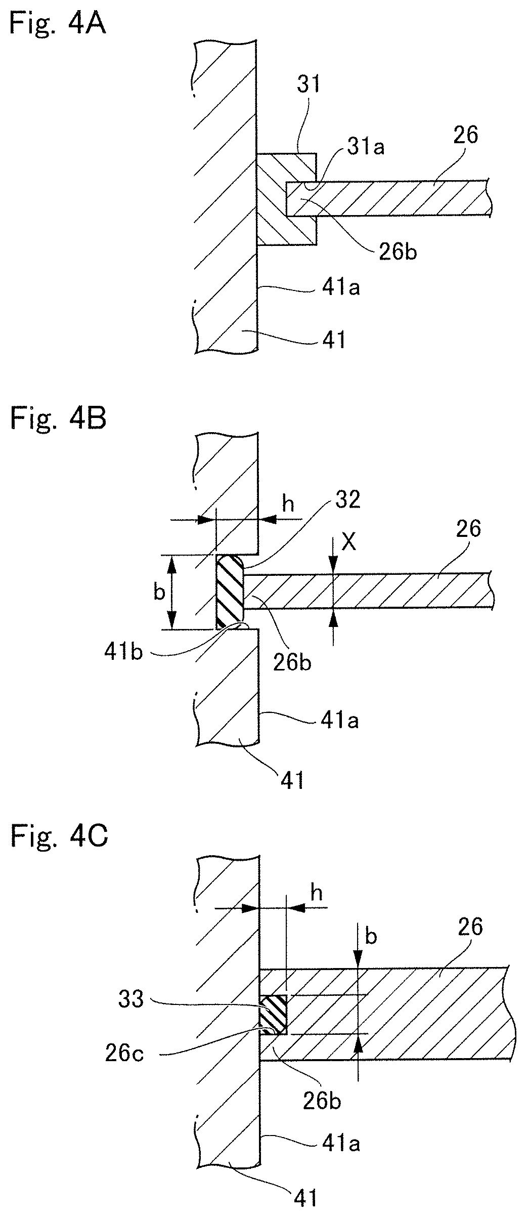
[0012] FIGS. 4A-4C are partially enlarged views illustrating a state where an end portion of the wall portion comes into contact with the pump apparatus via a seal.
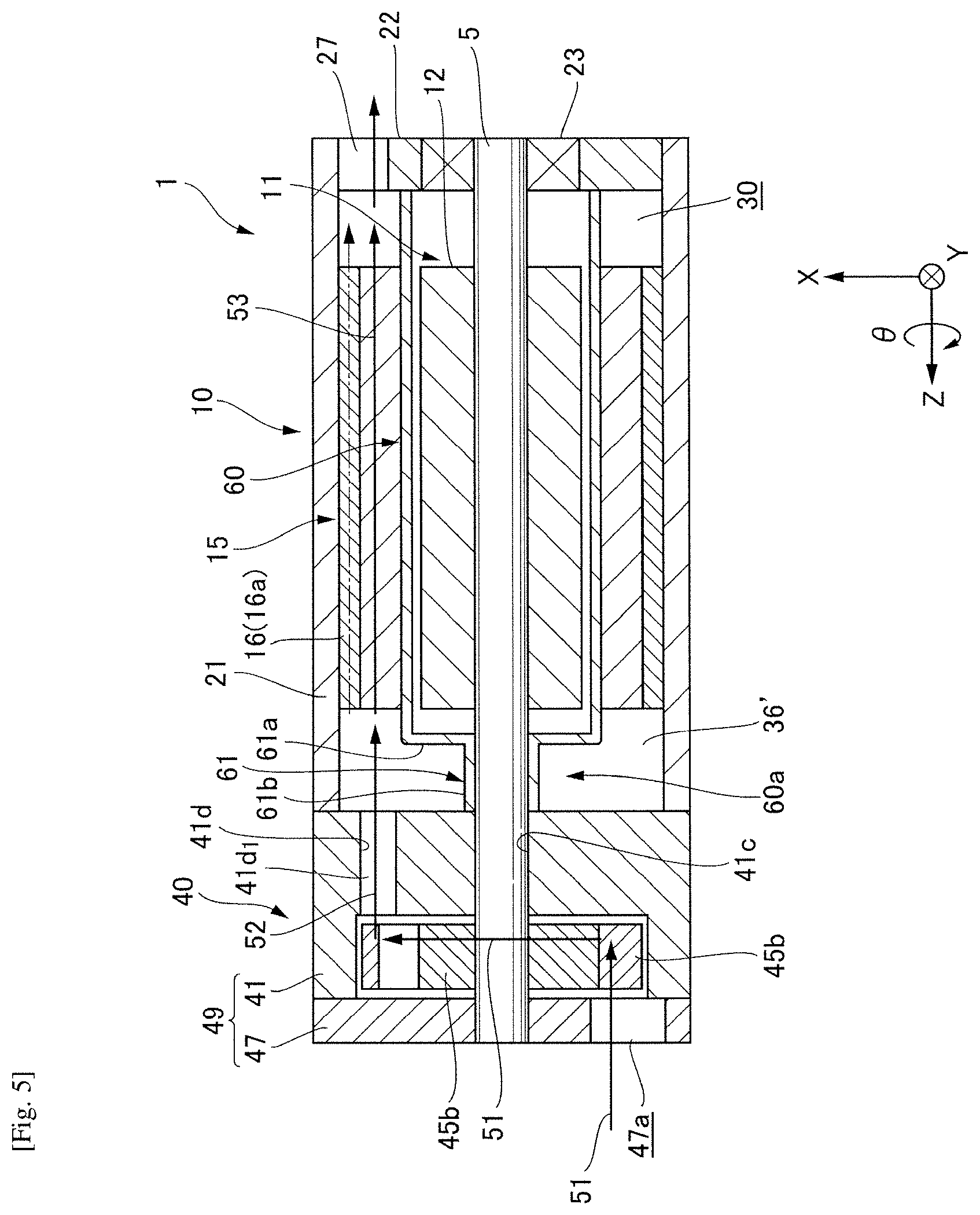
[0013] FIG. 5 is a cross-sectional view of a pump apparatus illustrating a modification example of the wall portion in the first example embodiment of the present disclosure.
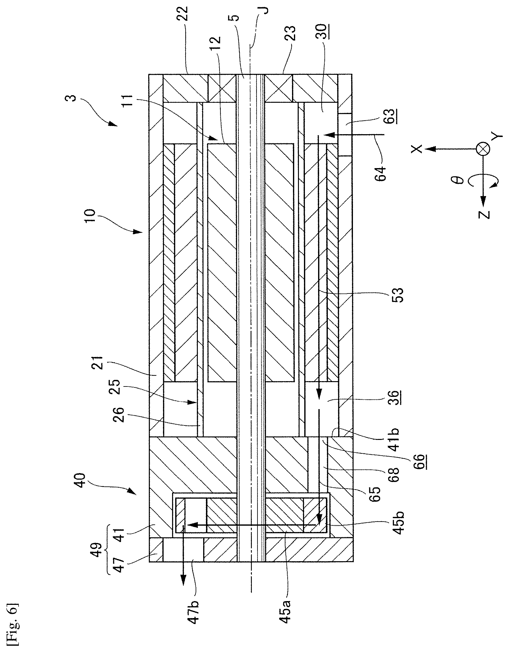
[0014] FIG. 6 is a cross-sectional view of a pump apparatus according to a second example embodiment of the present disclosure.
DETAILED DESCRIPTION
[0015] Hereinafter, with reference to the drawings, pump apparatuses according to example embodiments of the present disclosure will be described. However, it is intended that dimensions, materials, shapes, relative dispositions, and the like of constituent components disclosed as the example embodiments or illustrated in the drawings are merely explanatory examples and do not limit the scope of the present disclosure to the details described above. For example, expressions expressing relative or unique dispositions such as "in a certain direction", "along a certain direction", "parallel", "orthogonal", "center", "concentric", and "coaxial" express not only such dispositions in a strict sense but also express states relatively displaced with a tolerance, or at an angle or a distance to the extent that the same functions can be achieved. For example, expressions expressing states where subjects are equivalent to each other, such as "the same", "equal", and "homogeneous" express not only equivalent states in a strict sense but also express states having a tolerance or a difference to the extent that the same functions can be achieved is present. For example, expressions expressing shapes such as a quadrangular shape and a cylindrical shape express not only the shapes of a quadrangular shape and a cylindrical shape in a geometrically strict sense but also express shapes including uneven portions, chamfered portions, and the like within a range in which the same effects can be achieved. On the other hand, expressions such as "consisting of", "equipped with", "provided with", "including", and "having" a constituent element are not exclusive expressions excluding the presence of other constituent elements.
[0016] In addition, in the drawings, an XYZ coordinate system is suitably indicated as a three-dimensional orthogonal coordinate system. In the XYZ coordinate system, a Z-axis direction is a direction parallel to one direction in an axial direction of a central axis J illustrated in FIG. 1. An X-axis direction is a direction parallel to a width direction of a pump apparatus illustrated in FIG. 1, that is, an up-down direction in FIG. 1. A Y-axis direction is a direction orthogonal to both the X-axis direction and the Z-axis direction.
[0017] In addition, in the following description, a positive side in the Z-axis direction (positive Z-side) will be referred to as "a front side", and a negative side in the Z-axis direction (negative Z-side) will be referred to as "a rear side". The rear side and the front side are names simply used for description and do not limit actual positional relationships and directions. In addition, unless otherwise specified, the direction (Z-axis direction) parallel to the central axis J will be simply referred to as "an axial direction". A radial direction about the central axis J will be simply referred to as "a radial direction". A circumferential direction about the central axis J, that is, a direction (.theta.-direction) around the central axis J will be simply referred to as "a circumferential direction".
[0018] In this specification, the expression "extending in the axial direction" includes a case of extending in a direction inclined within a range of less than 45.degree. with respect to the axial direction, in addition to the case of strictly extending in the axial direction (Z-axis direction). In addition, in this specification, the expression "extending in the radial direction" includes a case of extending in a direction inclined within a range of less than 45.degree. with respect to the radial direction, in addition to the case of strictly extending in the radial direction, that is, a direction perpendicular to the axial direction (Z-axis direction).
First Example Embodiment
[0019] FIG. 1 is a cross-sectional view of a pump apparatus of the present example embodiment.
[0020] As illustrated in FIG. 1, a pump apparatus 1 of the present example embodiment has a motor section 10 and a pump section 40. The motor section 10 has a shaft 5 rotatably supported about the central axis J extending in the axial direction. The shaft 5 rotates about the central axis J. The motor section 10 and the pump section 40 are provided side by side along the axial direction.
<Motor Section 10>
[0021] The motor section 10 has a rotor 11, a stator 15, a housing 21, a wall portion 25, and a motor side discharge port 27.
[0022] The rotor 11 is fixed to an outer circumferential surface of the shaft 5 and rotates around the shaft 5. The stator 15 is positioned on an outer side of the rotor 11 in the radial direction. Therefore, the motor section 10 is an inner rotor motor.
[0023] The housing 21 accommodates the rotor 11 and the stator 15. In the housing 21, the front side (positive Z-side) and the rear side (negative Z-side) are open, and a bearing holding portion 22 is inserted into an opening portion of the housing 21 on the rear side. The wall portion 25 is provided between an inner circumferential surface 15a of the stator 15 and an outer circumferential surface 11a of the rotor 11 and partitions the stator 15 and the rotor 11. The motor side discharge port 27 is provided in the bearing holding portion 22 and leads to a space portion 30 surrounded by the housing 21, the wall portion 25, and a rear end portion of the stator 15. Hereinafter, each component will be described in detail.
(Housing 21)
[0024] As illustrated in FIG. 1, the housing 21 has a tubular shape. In more detail, the housing 21 has a cylindrical shape in which both ends about the central axis J are open. The material of the housing 21 is a metal, for example. The housing 21 holds the motor section 10.
[0025] The bearing holding portion 22 is fitted into and attached to an opening portion 21a of the housing 21 on the other side in the axial direction. The motor side discharge port 27 and a bearing 23 are provided in the bearing holding portion 22. The other end portion of the shaft 5 in the axial direction is inserted into the bearing 23 and is supported therein. An end portion of the housing 21 on one side in the axial direction is connected in a state of being in contact with a bottom surface 41a of a pump body 41 of the pump section 40 on the rear side in the axial direction.
[0026] An outer surface of the stator 15, that is, an outer surface of a core back portion 16 (which will be described below) is fitted onto an inner surface 21b of an intermediate portion of the housing 21 in the axial direction. Thus, the stator 15 is held in the housing 21.
(Rotor 11)
[0027] The rotor 11 has a rotor core 12 and a rotor magnet. The rotor core 12 surrounds the shaft 5 in the direction (.theta.-direction) around the axis and is fixed to the shaft 5. The rotor magnet is fixed to an outer circumferential portion of the rotor core 12 along the direction around the axis. The rotor core 12 and the rotor magnet rotate integrally with the shaft 5.
(Stator 15)
[0028] As illustrated in FIG. 2, the stator 15 surrounds the rotor 11 in the direction (.theta.-direction) around the axis and rotates the rotor 11 around the central axis J. The stator 15 has the core back portion 16, teeth portions 17, coils 18, and insulators (bobbins) 20. The shape of the core back portion 16 is a concentrically cylindrical shape with respect to the shaft 5. In the illustrated example embodiment, the core back portion 16 is made to have a cylindrical shape by disposing a plurality of split cores 16a which are split close to each other in the circumferential direction. That is, the core back portion 16 is a core back for the plurality of split cores 16a. The core back portion 16 may be a core back for a stator of a straight core made by bending a belt-shaped stator core.
[0029] The teeth portions 17 extend toward the shaft 5 from the inner surface of the core back portion 16. In the illustrated example embodiment, the teeth portions 17 extend toward the shaft 5 from the inner surface of each of the plurality of split cores 16a disposed in a cylindrical shape. A plurality of teeth portions are provided to be disposed at equal intervals in the circumferential direction of the inner surface of the core back portion 16. The coil 18 is constituted of a wound conductive wire 19. The coil 18 is provided in the insulator (bobbin) 20. The insulator (bobbin) 20 is mounted in each teeth portion 17.
(Wall Portion 25)
[0030] As illustrated in FIGS. 1 and 2, the wall portion 25 is provided between the inner circumferential surface 15a of the stator 15 and the outer circumferential surface 11a of the rotor 11 and partitions the stator 15 and the rotor 11. The wall portion 25 has a cylinder portion 26 which covers the outer circumferential surface 11a of the rotor 11 and extends in the axial direction of the shaft 5. A gap 28 is provided between an inner circumferential surface 26a of the cylinder portion 26 and the outer circumferential surface 11a of the rotor 11. Therefore, there is no concern that the rotor 11 will come into contact with the cylinder portion 26 when the rotor 11 rotates. The cylinder portion 26 is formed of a material (for example, a metal or a resin) transmitting a magnetic force. In this manner, the wall portion 25 can be easily provided by disposing the cylinder portion 26 in the gap 28 between the stator 15 and the rotor 11.
[0031] In the cylinder portion 26, one end portion 26b of the cylinder portion 26 in the axial direction comes into contact with the pump body 41 of a pump case 49, and the other end portion 26d of the cylinder portion 26 in the axial direction comes into contact with the bearing holding portion 22 mounted in the housing 21 of the motor section 10. Therefore, it is possible to prevent concern of an oil, which has been delivered to the inside of the motor section 10 from the pump section 40, flowing to a rotor region Ar where the rotor 11 is present. Therefore, degradation of the rotational efficiency of the rotor 11 can be curbed.
[0032] As illustrated in FIG. 4A, the one end portion 26b of the cylinder portion 26 in the axial direction may come into contact with the bottom surface 41a of the pump body 41 via a seal member 31. In the illustrated example embodiment, for example, the seal member 31 is made of an elastically deformable synthetic resin material and has an annular shape. A recessed portion 31a extending along the circumferential direction of the seal member 31 is provided in the intermediate portion in the radial direction on a surface of the seal member 31 on the other side in the axial direction. In a state where the one end portion 26b of the cylinder portion 26 in the axial direction is inserted into this recessed portion 31a, the seal member 31 comes into contact with the bottom surface 41a of the pump body 41 in an elastically deformed state. Therefore, it is possible to curb concern of deviation of the relative position between the one end portion 26b of the cylinder portion 26 in the axial direction and the seal member 31, and it is possible to prevent concern of a gap being generated between the seal member 31 and the bottom surface 41a of the pump body 41.
[0033] In addition, as illustrated in FIG. 4B, a seal member 32 may be disposed inside a recessed portion 41b provided on the bottom surface 41a of the pump body 41. In the illustrated example embodiment, the recessed portion 41b is provided on the bottom surface 41a of the pump body 41 in an annular shape in the circumferential direction. A cross-sectional shape of the recessed portion 41b is a quadrangular shape. The cross-sectional shape of the recessed portion 41b is not limited to a quadrangular shape and may be an arc shape or a shape in which a rectangle and an arc are combined. In addition, a width b of the recessed portion 41b is larger than a thickness X of the cylinder portion 26 such that the one end portion 26b of the cylinder portion 26 in the axial direction can be inserted thereinto. Moreover, a depth h of the recessed portion 41b has a size such that the seal member 32 and the one end portion 26b of the cylinder portion 26 in the axial direction can be inserted into the recessed portion 41b. In this manner, when the seal member 32 is disposed inside the recessed portion 41b and the one end portion 26b of the cylinder portion 26 in the axial direction is brought into contact with the seal member 32, the position of the seal member 32 can be set in a contact state inside the recessed portion 41b. Therefore, when the one end portion 26b of the cylinder portion 26 in the axial direction is brought into contact with the seal member 32, in a state where the seal member 32 is elastically deformed inside the recessed portion 41b, the cylinder portion 26 and the seal member 32 come into contact with each other, and the seal member 32 and the recessed portion 41b come into contact with each other. Therefore, it is possible to curb generation of a gap between the seal member 32 and the recessed portion 41b and a gap between the seal member 32 and the cylinder portion 26.
[0034] In addition, as illustrated in FIG. 4C, a seal member 33 may be disposed inside a recessed portion 26c provided in the one end portion 26b of the cylinder portion 26 in the axial direction. In this case, the recessed portion 26c is provided on a distal end surface of the one end portion 26b of the cylinder portion 26 in the axial direction in an annular shape in the circumferential direction. A cross-sectional shape of the recessed portion 26c is a quadrangular shape. The cross-sectional shape of the recessed portion 26c is not limited to a quadrangular shape and may be an arc shape or a shape in which a rectangle and an arc are combined. In addition, the width b of the recessed portion 26c has a size such that the seal member 33 can be inserted thereinto, for example, a size approximately the same as or slightly smaller than the width of the seal member 33 when the seal member 33 is in a natural state. Moreover, the depth h of the recessed portion 26c has a size such that a part of the seal member 33 can protrude from the recessed portion 26c when the seal member 33 is inserted into the recessed portion 26c. Therefore, when the one end portion 26b of the cylinder portion 26 in the axial direction is brought into contact with the bottom surface 41a of the pump body 41, the seal member 33 comes into contact with the bottom surface 41a of the pump body 41 in an elastically deformed state, and the seal member 33 adheres thereto inside the recessed portion 26c. Therefore, it is possible to further curb generation of a gap between the seal member 33 and the recessed portion 26c and a gap between the seal member 33 and the bottom surface 41a.
(Motor Side Discharge Port 27)
[0035] As illustrated in FIG. 1, the motor side discharge port 27 is provided in the bearing holding portion 22. The motor side discharge port 27 is provided in a circumferential edge portion of the bearing holding portion 22. The motor side discharge port 27 communicates with the space portion 30 surrounded by the other side end of the stator 15 in the axial direction, the housing 21, and the wall portion 25.
<Pump Section 40>
[0036] As illustrated in FIG. 1, the pump section 40 is positioned on one side of the motor section 10 in the axial direction, in detail, the front side (positive Z-axis side). The pump section 40 is driven by the motor section 10 via the shaft 5. The pump section 40 has the pump body 41, a pump rotor 45, and a pump cover 47. Hereinafter, the pump cover 47 and the pump body 41 will be referred to as the pump case 49.
(Pump Body 41)
[0037] The pump body 41 is fixed to the end portion of the housing 21 on the front side of the motor section 10. The pump body 41 has a pump chamber 42 which is depressed to the rear side (negative Z-side) from the surface on the front side (positive Z-side) and accommodates the pump rotor 45. The shape of the pump chamber 42 viewed in the axial direction is a circular shape.
[0038] The pump body 41 is open at both ends in the axial direction to allow the shaft 5 to pass therethrough, and an opening on the front side has a penetration hole 41c open in the pump chamber 42. The opening of the penetration hole 41c on the rear side is open on the motor section 10 side. The penetration hole 41c functions as a bearing member rotatably supporting the shaft 5.
(Pump Rotor 45)
[0039] The pump rotor 45 is attached to the shaft 5. In more detail, the pump rotor 45 is attached to the end portion of the shaft 5 on the front side. The pump rotor 45 has an inner rotor 45a which is attached to the shaft 5 and an outer rotor 45b which surrounds the outer side of the inner rotor 45a in the radial direction. The inner rotor 45a has a ring shape. The inner rotor 45a is a gear having teeth on the outer surface in the radial direction.
[0040] The inner rotor 45a is fixed to the shaft 5. In more detail, the end portion of the shaft 5 on the front side is press-fitted into the inner rotor 45a. The inner rotor 45a rotates together with the shaft 5 in the direction (.theta.-direction) around the axis. The outer rotor 45b has a ring shape surrounding the outer side of the inner rotor 45a in the radial direction. The outer rotor 45b is a gear having teeth on the inner surface in the radial direction.
[0041] The inner rotor 45a and the outer rotor 45b mesh with each other, and the outer rotor 45b rotates when the inner rotor 45a rotates. That is, the pump rotor 45 rotates due to rotation of the shaft 5. In other words, the motor section 10 and the pump section 40 have the same rotation axis. Therefore, the electric oil pump can be prevented from having an increased size in the axial direction. In addition, when the inner rotor 45a and the outer rotor 45b rotate, the volume of a space between meshed parts of the inner rotor 45a and the outer rotor 45b changes. A region where the volume decreases becomes a pressurization region Ap, and a region where the volume increases becomes a negative pressure region Ad. A pump side suction port 47a is disposed on one side of the negative pressure region of the pump rotor 45 in the axial direction. Here, an oil which has been suctioned into the pump chamber 42 through the pump side suction port 47a is accommodated in a volume part between the inner rotor 45a and the outer rotor 45b and is sent to a delivery hole 41d side allowing the pump section 40 and the motor section 10 to communicate with each other. Thereafter, the oil is delivered to the inside of the motor section 10 through the delivery hole 41d.
(Pump Body 41)
[0042] The delivery hole 41d connecting the pump chamber 42 and a stator region As inside the motor section 10 to each other is provided in the pump body 41. The opening of the delivery hole 41d on the pump chamber 42 side leads to the pressurization region Ap of the pump rotor 45. On the other hand, the opening of the delivery hole 41d on the motor section 10 side, that is, a pump side delivery port 41d1 leads to the stator region As inside the motor section 10. Therefore, an oil inside the pump section 40 is delivered to the inside of the stator region As through the pump side delivery port 41d1 via the delivery hole 41d due to pressurization of the pump section 40.
(Pump Cover 47)
[0043] The pump cover 47 is attached to the front side of the pump body 41. The pump cover 47 has a disk shape extending in the radial direction. The pump cover 47 blocks the opening of the pump chamber 42 on the front side.
[0044] The pump section 40 has the pump side suction port 47a. The pump side suction port 47a is provided in the pump cover 47. The pump side suction port 47a is open on the surface of the pump cover 47 on the front side. The pump side suction port 47a leads to the pump chamber 42 and allows an oil to be suctioned into the pump chamber 42.
[0045] When the shaft 5 rotates in one direction (negative .theta.-direction) in the circumferential direction, an oil is suctioned into the pump chamber 42 through the pump side suction port 47a. The oil which has been suctioned into the pump chamber 42 is sent to the delivery hole 41d side by the pump rotor 45. Thereafter, the oil is delivered to the inside of the motor section 10 via the delivery hole 41d by the pump rotor 45. The oil which has been delivered to the inside of the motor section 10 passes through the inside of the stator 15. Therefore, the motor section 10 can be cooled.
[0046] Next, a cooling structure of the pump apparatus 1 according to the present example embodiment will be described. In the present example embodiment, an oil which has been supplied from an external apparatus flows inside the pump section 40 through the pump side suction port 47a by the pump rotor 45, is delivered to the inside of the motor section 10, and circulates inside the motor section 10, thereby realizing cooling of the stator 15.
[0047] The pump apparatus 1 has a first flow channel 51 for causing an oil to flow into the pump section 40 through the pump side suction port 47a; a second flow channel 52 for causing an oil to flow to a region on a side which is partitioned by the wall portion 25 and on which the stator 15 is present inside the motor section 10, through the pump side delivery port 41d1; and a third flow channel 53 provided inside the stator 15 to cause an oil to flow into the stator 15. Hereinafter, details of each flow channel will be described.
(First Flow Channel 51)
[0048] The first flow channel 51 is provided between the pump side suction port 47a and the pressurization region Ap inside the pump section 40. In the example illustrated in FIG. 1, the first flow channel 51 is a flow channel for causing an oil delivered through the pump side suction port 47a to move to the pressurization region Ap from the negative pressure region Ad of the pump rotor 45.
(Second Flow Channel 52)
[0049] The second flow channel 52 is provided between the pump chamber 42 of the pump section 40 and a space portion 36 inside the motor section 10. In the example illustrated in FIG. 2, the second flow channel 52 is a flow channel for connecting the pump chamber 42 and the space portion 36 surrounded by the housing 21 on the pump section 40 side of the stator region As and the wall portion 25 to each other via the delivery hole 41d. An oil flowing in the second flow channel 52 flows through the delivery hole 41d and is delivered to the inside of the space portion 36 through the pump side delivery port 41d1. An oil which has been delivered to the inside of the space portion 36 is in a state of filling the inside of the space portion 36.
(Third Flow Channel 53)
[0050] The third flow channel 53 is a flow channel leading to the space portion 36 to cause an oil to flow into the stator 15. In the example illustrated in FIG. 2, as illustrated in FIG. 2, the third flow channel 53 is a flow channel which is provided between the coils 18 respectively wound around a pair of teeth portions 17 adjacent to each other in the circumferential direction and leads to the rear end from the front end of the stator 15. Regarding the teeth portions 17, as described above, the core back portion 16 is provided on a base end side of the teeth portions 17. A protrusion portion 17a protruding in the circumferential direction of the stator is provided on a distal end side of the teeth portion 17. Moreover, the cylinder portion 26 is disposed close to the distal end portions of a pair of teeth portions 17 adjacent to each other in the circumferential direction. Therefore, a space which is surrounded by the core back portion 16, the protrusion portion 17a, and the wall portion 25 and extends in the axial direction is further formed between the coils 18 of a pair of teeth portions 17 adjacent to each other in the circumferential direction. This space is the third flow channel 53. Thus, an oil which has flowed into the third flow channel 53 flows to the rear end from the front end of the third flow channel 53 and is discharged via the space portion 30 and the motor side discharge port 27.
[0051] In this manner, since an oil flows near the coils 18 in the third flow channel 53, heat generated from the coils can be effectively absorbed by the oil. Thus, the stator 15 can be efficiently cooled, and the rotor magnet can be prevented from being demagnetized due to heat radiation of the stator 15. In addition, although an oil flowing into the motor section 10 flows inside the stator 15, since the wall portion 25 prevents an oil from flowing into the region where the rotor 11 is present, there is no concern that the rotational efficiency of the rotor 11 will be degraded.
[0052] A flow channel for causing an oil absorbing heat generated from the coils 18 of the stator 15 to flow is not limited to the inside of the stator 15 and may be provided between the stator 15 and the housing 21. In the example embodiment illustrated in FIG. 2, a groove portion 55 extending in the axial direction may be provided on the outer surface of the split core 16a of the stator 15 to form a flow channel, that is, a sixth flow channel 56 in which an oil can circulate by covering the opening of the groove portion 55 with the inner surface of the housing 21. As illustrated in FIG. 1, the front end portion of the sixth flow channel 56 leads to the space portion 36, and the rear end portion of the sixth flow channel 56 leads to the space portion 30. Therefore, an oil which has been delivered to the inside of the space portion 36 through the pump side delivery port 41d1 flows in the sixth flow channel 56 and is delivered to the space portion 30 on the rear side. Therefore, heat generated from the coils 18 can be transferred to and absorbed by the oil via the teeth portions 17 and the core back portion 16 of the stator 15 and can cool the stator 15.
[0053] The sixth flow channel 56 is not limited to a linearly extending flow channel. The sixth flow channel 56 may be spirally provided such that the sixth flow channel 56 advances in the circumferential direction of the stator 15 toward the axial direction on the outer surface of the stator 15 or may be provided in a wave shape such that the sixth flow channel 56 changes the direction to the other side in the circumferential direction after changing the direction to one side in the circumferential direction of the stator 15 toward the axial direction on the outer surface of the stator 15.
[0054] In addition, the coil 18 of the stator 15 may be resin-molded. When the coil 18 is resin-molded, the coil 18 is covered with a resin, and the resin also flows into a space between the coils 18 adjacent to each other. Therefore, the contact area between an oil and the coils 18 can be increased via the resin. Therefore, when an oil flows on the surfaces of the resin-molded coils 18, heat generated from the coils can be effectively cooled. In addition, unevenness on the surface of the coil group can be reduced by covering the coils exposed to the surface side of the coil group wound around the teeth portions 17 in resin-molding with a resin. Therefore, an oil can flow more smoothly.
[0055] In addition, the wall portion 25 and the stator 15 may be integrally molded products formed of a resin. In the example embodiment illustrated in FIG. 3, the wall portion 25 is integrally connected to the stator 15 via the teeth portions 17 of the stator 15. That is, the stator 15 and the wall portion 25 are a part of a single member. In this manner, when the wall portion 25 and the stator 15 are integrally molded products formed of a resin, a gap between the distal end portions of the teeth portions 17 and the wall portion 25 can be eliminated. Therefore, the amount of an oil leaking out from the third flow channel 53 can be reduced, and cooling efficiency of the stator 15 can be improved.
[0056] In addition, as illustrated in FIG. 1, a space between the other end portion of the stator 15 in the axial direction and the bearing holding portion 22 attached to the housing 21 inside the motor section 10, that is, the space portion 30 surrounded by the stator 15, the wall portion 25, and the housing 21 is provided inside the motor section 10. However, this space portion 30 can be filled with an oil. When this space portion 30 is provided in the motor section 10, an oil flowing out from the third flow channel 53 is in a state of filling the space portion 30 and is discharged through the motor side discharge port 27. Therefore, an oil can be efficiently discharged through the motor side discharge port 27.
[0057] In this manner, in the pump apparatus 1 according to the first example embodiment, when the motor section 10 is driven, an oil passes through the first flow channel 51 and flows into the pump section 40. A part of the oil which has flowed into the pump section 40 passes through the second flow channel 52 and is delivered to the space portion 36 through the pump side delivery port 41d1. The second flow channel 52 is present on the stator region As side partitioned by the wall portion 25 inside the motor section 10. Therefore, since the wall portion 25 prevents an oil flowing in the second flow channel 52 from flowing to the rotor 11 side, most of the oil delivered through the pump side delivery port 41d1 can flow into the stator 15 via the third flow channel 53. Thus, it is possible to realize the pump apparatus 1 in which the stator 15 can be cooled using an oil circulating in the pump section 40, without having the rotational efficiency of the rotor 11 being degraded.
Modification Example of First Example Embodiment
[0058] Next, a modification example of the pump apparatus 1 according to the first example embodiment will be described. FIG. 5 is a cross-sectional view of the pump apparatus 1 illustrating a modification example of the wall portion 25 in the first example embodiment. In the modification example of the first example embodiment, only the points different from the first example embodiment will be described. The same reference signs are applied to parts having the same form as the first example embodiment, and description thereof will be omitted.
[0059] As illustrated in FIG. 5, a wall portion 60 disposed inside the motor section 10 has a step portion 61 in which a front side portion 60a on the pump section 40 side of one end portion of the rotor 11 in the axial direction is bent to the shaft 5 side and extends to the pump section 40 side along the shaft 5. The step portion 61 has a ring-shaped end wall portion 61a and a cylindrical circumferential wall portion 61b. The circumferential wall portion 61b continues to the inner end of the end wall portion 61a in the radial direction and extends to the front side in the axial direction. The end wall portion 61a extends in the up-down direction from the rear end of the circumferential wall portion 61b in the axial direction. The shaft 5 internally penetrates the circumferential wall portion 61b. A gap is provided between the inner circumferential surface of the circumferential wall portion 61b and the outer circumferential surface of the shaft 5, and the shaft 5 can rotate.
[0060] In this manner, when the step portion 61 is provided on the front side of the wall portion 25 in the axial direction, a region of a space portion 36' between one end of the stator 15 in the axial direction and the pump section 40 can be increased. Therefore, the amount of an oil delivered from the second flow channel 52 to fill the inside of the space portion 36' can be increased. Therefore, it is possible to efficiently supply an oil flowing to the third flow channel 53 from the space portion 36'.
Second Example Embodiment
[0061] Next, a pump apparatus 3 according to a second example embodiment of the present disclosure will be described. In the second example embodiment, only the points different from the first example embodiment will be described. The same reference signs are applied to parts having the same form as the first example embodiment, and description thereof will be omitted. FIG. 6 is a cross-sectional view of the pump apparatus 3 according to the second example embodiment.
[0062] A motor side suction port 63 for suctioning an oil into the motor section 10 between the housing 21 and the wall portion 25 is provided in the motor section 10. In the example embodiment illustrated in FIG. 6, the motor side suction port 63 is provided in the housing 21 on the rear side of the rear end portion of the stator 15. In addition, a fourth flow channel 64 for causing an oil which has passed through the motor side suction port 63 to flow into the motor section is provided in the pump apparatus 3. In the example embodiment illustrated in FIG. 6, an oil flowing out from a speed change gear (not illustrated) flows into the motor section 10 through the fourth flow channel 64. That is, an oil passing through the fourth flow channel 64 flows into the space portion 30 provided on the rear side of the motor section 10 described above. The third flow channel 53 illustrated in FIG. 1 as described above is provided in the stator 15. However, the present example embodiment differs in that the direction of a flow of an oil is a direction toward the front side from the rear side of the stator 15.
[0063] A pump side introduction port 66 for introducing an oil inside the motor section 10 into the pump section 40 using a negative pressure of the pump section 40 is provided in the pump body 41 of the pump section 40. In the example embodiment illustrated in FIG. 6, the pump side introduction port 66 is open in the space portion 36 provided on the front side of the motor section 10.
[0064] In addition, a fifth flow channel 65 for introducing an oil inside the motor section 10 into the pump section 40 through the pump side introduction port 66 is provided in the pump body 41. In the example embodiment illustrated in FIG. 6, an introduction hole 68, in which one end side is open in the negative pressure region Ad of the pump section 40 and the other end side leads to the pump side introduction port 66, is provided in the pump body 41. The fifth flow channel 65 connects the space portion 36 and the negative pressure region Ad of the pump section 40 to each other via the introduction hole 68. A pump side discharge port 47b for discharging an oil which has been suctioned into the pump section 40 is provided in the pump cover 47. The pump side discharge port 47b leads to the pressurization region Ap of the pump rotor 45. The pump apparatus 1 of the second example embodiment does not have the pump side delivery port 41d1, the motor side discharge port 27, and the pump side suction port 47a illustrated in FIG. 1.
[0065] In the pump apparatus 1 according to the second example embodiment, when the motor section 10 is driven, an oil flowing in the fourth flow channel 64 flows into the space portion 30 via the motor side suction port 63. The oil which has flowed into the space portion 30 flows toward the front side from the rear side of the motor section 10 via the third flow channel 53. The oil which has flowed out from the third flow channel 53 is introduced into the pump section 40 through the pump side introduction port 66. Here, since an oil which has flowed into the motor section 10 is prevented by the wall portion 25 from flowing to the rotor 11 side, most of the oil which has been delivered to the inside of the motor section 10 can flow into the stator 15 via the third flow channel 53. Thus, it is possible to realize the pump apparatus 1 in which the stator 15 can be cooled using an oil flowing into the motor section 10, without having the rotational efficiency of the rotor 11 being degraded.
[0066] In addition, as described above, the space portion 36 surrounded by the stator 15, the wall portion 25, and the housing 21 is provided between one end portion of the stator 15 in the axial direction and one end portion of the housing 21 in the axial direction inside the motor section 10. However, this space portion 36 may be able to be filled with an oil. In the illustrated example embodiment, the space portion 36 surrounded by the stator 15, the wall portion 25, and the housing 21 is provided between the front end portion of the stator 15 in the axial direction and the bottom surface 41a of the pump body 41 of the pump section 40 inside the motor section 10. Since the space portion 36 can be filled with an oil flowing out from the third flow channel 53 by providing this space portion 36, an oil can be efficiently introduced into the pump section 40 through the pump side introduction port 66.
[0067] Hereinabove, preferable example embodiments of the present disclosure have been described. However, the present disclosure is not limited to these example embodiments, and various modifications and changes can be made within a range of the gist thereof.
[0068] While example embodiments of the present disclosure have been described above, it is to be understood that variations and modifications will be apparent to those skilled in the art without departing from the scope and spirit of the present disclosure. The scope of the present disclosure, therefore, is to be determined solely by the following claims.
* * * * *
D00000
D00001
D00002
D00003
D00004
D00005
D00006
XML
uspto.report is an independent third-party trademark research tool that is not affiliated, endorsed, or sponsored by the United States Patent and Trademark Office (USPTO) or any other governmental organization. The information provided by uspto.report is based on publicly available data at the time of writing and is intended for informational purposes only.
While we strive to provide accurate and up-to-date information, we do not guarantee the accuracy, completeness, reliability, or suitability of the information displayed on this site. The use of this site is at your own risk. Any reliance you place on such information is therefore strictly at your own risk.
All official trademark data, including owner information, should be verified by visiting the official USPTO website at www.uspto.gov. This site is not intended to replace professional legal advice and should not be used as a substitute for consulting with a legal professional who is knowledgeable about trademark law.