Clothes Processing Apparatus
LEE; Sangyong
U.S. patent application number 16/488481 was filed with the patent office on 2019-12-19 for clothes processing apparatus. The applicant listed for this patent is LG Electronics Inc.. Invention is credited to Sangyong LEE.
| Application Number | 20190382938 16/488481 |
| Document ID | / |
| Family ID | 63252840 |
| Filed Date | 2019-12-19 |


View All Diagrams
| United States Patent Application | 20190382938 |
| Kind Code | A1 |
| LEE; Sangyong | December 19, 2019 |
CLOTHES PROCESSING APPARATUS
Abstract
The present invention relates a package assembly comprising: a support unit which can seat any one of a first cabinet and a second cabinet on the other one of the first cabinet and the second cabinet to carry the first cabinet and the second cabinet as one set.
| Inventors: | LEE; Sangyong; (Seoul, KR) | ||||||||||
| Applicant: |
|
||||||||||
|---|---|---|---|---|---|---|---|---|---|---|---|
| Family ID: | 63252840 | ||||||||||
| Appl. No.: | 16/488481 | ||||||||||
| Filed: | February 23, 2018 | ||||||||||
| PCT Filed: | February 23, 2018 | ||||||||||
| PCT NO: | PCT/KR2018/002229 | ||||||||||
| 371 Date: | August 23, 2019 |
| Current U.S. Class: | 1/1 |
| Current CPC Class: | B65D 81/113 20130101; D06F 39/001 20130101; B65D 81/107 20130101; D06F 39/00 20130101; B65D 85/64 20130101; B65D 25/10 20130101 |
| International Class: | D06F 39/00 20060101 D06F039/00; B65D 81/113 20060101 B65D081/113; B65D 85/64 20060101 B65D085/64 |
Foreign Application Data
| Date | Code | Application Number |
|---|---|---|
| Feb 24, 2017 | KR | 10-2017-0024931 |
Claims
1. A packaging assembly comprising: a support part configured to seat one of the first cabinet and a second cabinet on top of the other one of the first cabinet and the second cabinet first cabinet and the second cabinet on top of the other one of the first cabinet and the second cabinet to transport the first cabinet and the second cabinet as one set.
2. The packaging assembly of claim 1, wherein the support part comprises a support frame configured to accommodate the first cabinet therein and support the second cabinet placed thereon.
3. The packaging assembly of claim 2, wherein the support frame comprises: an upper frame spaced apart from each corner of a top surface of the first cabinet; and a plurality of side frames extending downward from each vertex of the upper frame.
4. The packaging assembly of claim 3, further comprising: an upper shock absorption member detachably provided to a corner of a top surface of the first cabinet to support the upper frame; and a side shock absorption member detachably provided to side corners of the first cabinet to contact the side frames.
5. The packaging assembly of claim 4, further comprising: a lower shock absorption member detachably arranged on a bottom surface of the first cabinet to support the first cabinet and the side shock absorption member.
6. The packaging assembly of claim 5, wherein the upper shock absorption member is provided with an upper groove at a corner of the upper shock absorption member, the upper groove accommodating at least one of the upper frame and the side frame.
7. The packaging assembly of claim 6, wherein the upper groove comprises: a first groove defined by one stepped corner of the upper shock absorption member to accommodate the upper frame; and a second groove defined by a stepped corner adjacent to opposite ends of the one corner to accommodate the side frame.
8. The packaging assembly of claim 4, wherein the side shock absorption member comprises: a side groove defined by a stepped corner of the side shock absorption member positioned farthest from the first cabinet, the side groove accommodating the side frame.
9. The packaging assembly of claim 5, wherein the side frame extends from the upper frame to a lower end of the lower shock absorption member, wherein the lower shock absorption member comprises a lower groove formed at each vertex thereof to accommodate the side frame.
10. The packaging assembly of claim 9, wherein the lower shock absorption member comprises an accommodation groove formed in a top surface thereof to accommodate a lower portion of the first cabinet.
11. The packaging assembly of claim 10, further comprising: a lower accommodation part configured to accommodate a lower portion of the lower shock absorption member and fix lower ends of the plurality of side frames.
12. The packaging assembly of claim 11, wherein the lower accommodation part is formed of a material having high brittleness.
13. The packaging assembly of claim 1, wherein the first cabinet comprises a first clothes accommodation part configured to accommodate clothes therein, wherein the support part comprises a fixing part arranged on the second cabinet to support the first clothes accommodation part.
14. The packaging assembly of claim 13, wherein the second cabinet comprises a second clothes accommodation part configured to accommodate clothes therein, wherein the fixing part is supported by the second clothes accommodation part to support the first clothes accommodation part.
15. The packaging assembly of claim 14, wherein the fixing part is supported by the second clothes accommodation part and arranged through a top surface of the second cabinet and a bottom surface of the first cabinet to support the first clothes accommodation part.
16. The packaging assembly of claim 15, wherein the fixing part comprises: a closing fixing part arranged on an top surface of the second clothes accommodation part so as to be parallel to the top surface of the second cabinet; and a supporting fixing part coupled to an upper portion of the closing fixing part to support the first clothes accommodation part.
17. The packaging assembly of claim 16, wherein the closing fixing part comprises: a closing body supported on the top surface of the second clothes accommodation part to close a penetrated portion of the second cabinet; a slide groove formed in a top surface of the closing body to guide a coupling position of the supporting fixing part; and a coupling groove formed the top surface of the closing body and coupled with the supporting fixing part to fix the supporting fixing part.
18. The packaging assembly of claim 17, wherein the supporting fixing part comprises: a fixing body fixed to the closing fixing part to support the first clothes accommodation part; a slide rib protruding from the fixing body so as to slide in the slide groove; and a coupling protrusion protruding from the fixing body so as to be inserted into the coupling groove and coupled thereto.
19. The packaging assembly of claim 18, wherein one of the coupling protrusion and the coupling groove is provided with a magnetic force generator configured to generate a magnetic field, and the other one of the coupling protrusion and the coupling groove is provided with a magnetic member magnetized by the magnetic field of the magnetic force generator.
20. The packaging assembly of claim 13, wherein the first cabinet further comprises a rear panel defining a rear surface of the first cabinet and detachably provided to the first cabinet, wherein the fixing part is removed from the second cabinet by separating the rear panel from the first cabinet.
Description
CROSS-REFERENCE TO RELATED APPLICATIONS
[0001] This application is a National Stage application under 35 U.S.C. .sctn. 371 of International Application No. PCT/KR2018/002229, filed on Feb. 23, 2018, which claims the benefit of Korean Application No. 10-2017-0024931, filed on Feb. 24, 2017. The disclosures of the prior applications are incorporated by reference in their entirety.
TECHNICAL FIELD
[0002] The present invention relates to a packaging assembly of a laundry treating apparatus.
BACKGROUND ART
[0003] In general, the term "laundry treating apparatus" refers to an apparatus capable of performing washing and drying or either washing or drying of clothes and the like. Here, the laundry treating apparatus may perform only the washing or drying function, or both the washing function and the drying function. Recently, washing machines provided with a steam supply device to perform a refresh function of removing wrinkles, odors, static electricity, and the like from clothes have been used.
[0004] Conventional laundry treating apparatuses are divided into a front loading type and a top loading type according to a retrieval direction of clothes. A typical example of this horizontal type is a drum washing machine or a drum dryer.
[0005] The front load type laundry treating apparatus refers to a laundry treating apparatus that has an opening formed in the front and a rotary shaft of the drum parallel to the ground or inclined with respect to the ground at a constant angle. The top load type laundry treating apparatus has an opening formed at the top and a rotary shaft of the drum vertically with respect to the ground.
[0006] These laundry treating apparatuses are gradually increasing in size in response to the demand of users in recent years. In other words, the size of the washing machine used for home use is gradually increasing.
[0007] Generally, each household is equipped with one high-capacity laundry treating apparatus. Accordingly, when the laundry is to be washed by classifying the clothes according to the types of the clothes, the laundry treating apparatus is used many times. For example, when laundry such as adult clothes and laundry such as underwear or baby clothes need to be separately washed, the laundry treating apparatus will be used to wash the latter laundry after washing of the former laundry is completed. As a result, a long time and large energy consumption are required to perform the washing operation.
[0008] Further, it is not desirable in terms of energy saving to use a large laundry treating apparatus in washing a small amount of clothing as in the conventional cases. Most washing phases provided in large laundry treating apparatuses assume a large amount of laundry, and thus consume a large amount of water. In addition, they cause large power consumption as they need to rotate a large drum or inner tub.
[0009] In addition, since the washing phase assumes a large amount of laundry, a relatively long time is taken for washing.
[0010] In addition, since the large laundry treating apparatus is provided with a washing phase assuming typical clothes, it may not be suitable for washing of delicate fabrics such as underwear or baby clothes.
[0011] Further, a large laundry treating apparatus is not suitable for a case where a small amount of laundry needs to be frequently washed. Consumers collect laundry for a few days or a longer period to wash the laundry at a time. It is not good in terms of cleanliness to leave underwear and baby clothes unwashed for a long time. When the laundry is left unwashed for a long time, stains are likely to stick to the fabrics and thus the laundry is not thoroughly washed.
[0012] Accordingly, there is a need for a small laundry treating apparatus which has a much smaller capacity than the conventional large laundry treating apparatus.
[0013] However, even when small-size laundry treating apparatuses are used, it is not desirable in terms of space utilization and aesthetics to install two laundry treating apparatuses side by side in the same house.
[0014] In recent years, in order to address the issues described above, a laundry treating apparatus combining a small laundry treating apparatus and a large laundry treating apparatus has emerged.
[0015] Accordingly, a small amount of clothing can be washed in the small laundry treating apparatus, and a large amount of clothing or bulky clothing can be washed in the large laundry treating apparatus. As a result, space utilization may be improved, and water, energy, and time may be saved.
[0016] However, the large laundry treating apparatus and the small laundry treating apparatus need to be individually packed and transported, thereby causing inconvenience.
[0017] In particular, in the case where the large laundry treating apparatus and the small laundry treating apparatus constitute one set, the large laundry treating apparatus and the small laundry treating apparatus need to be packed separately and then transported, which causes inconvenience.
[0018] Manufacturers undergo inconvenience as they are required to pack or transport large laundry treating apparatuses and small laundry treating apparatuses separately rather than packing a large laundry treating apparatus and a small laundry treating apparatuses together as a set.
[0019] Sellers also undergo inconvenience as they are required to display the large laundry treating apparatuses and the small laundry treating apparatuses separately, or to rearrange and classify each pair of the large laundry treating apparatus and the small laundry treating apparatus.
[0020] As the large laundry treating apparatus and the small laundry treating apparatus are separately packed and arranged, consumers may not recognize that the large laundry treating apparatus and the small laundry treating apparatus are configured in pair.
[0021] In addition, since the packed large laundry treating apparatus and the packed small laundry treating apparatus are not arranged in position for actual use, consumers may not have a clear understanding of the layout and structure of the pair.
[0022] Further, when the large laundry treating apparatus and the small laundry treating apparatus are stacked and transported, the laundry treating apparatuses may be damaged by an impact.
[0023] In addition, the internal components of the large laundry treating apparatus and the small laundry treating apparatus are likely to be shaken and damaged during the transportation, and thus each of the laundry treating apparatuses needs a separate member for preventing shaking.
DISCLOSURE
Technical Problem
[0024] An object of the present invention is to provide a packaging assembly for packaging and transporting the large laundry treating apparatus and the small laundry treating apparatus as a pair.
[0025] Another object of the present invention is to provide a packaging assembly for packaging and transporting the large laundry treating apparatus and the small laundry treating apparatus together at a time.
[0026] Another object of the present invention is to provide a packaging assembly for preventing breakage and damage in packaging and transporting the large laundry treating apparatus and the small laundry treating apparatus.
[0027] Another object of the present invention is to provide a packaging assembly capable of preventing internal components of the large laundry treating apparatus and the small laundry treating apparatus from shaking as one device.
[0028] Another object of the present invention is to provide a packaging assembly for packaging and transporting the large laundry treating apparatus and the small laundry treating apparatus as one package such that consumers recognize the laundry treating apparatuses as one pair.
[0029] Another object of the present invention is to provide a packaging assembly for packaging the large laundry treating apparatus and the small laundry treating apparatus arranged in position for actual use.
Technical Solution
[0030] In one aspect of the present invention, provided herein is a packaging assembly including a support part configured to seat one of the first cabinet and a second cabinet on top of the other one of the first cabinet and the second cabinet first cabinet and the second cabinet on top of the other one of the first cabinet and the second cabinet to transport the first cabinet and the second cabinet as one set.
[0031] The support part may include a support frame configured to accommodate the first cabinet therein and support the second cabinet placed thereon.
[0032] The support frame may include an upper frame spaced apart from each corner of a top surface of the first cabinet, and a plurality of side frames extending downward from each vertex of the upper frame.
[0033] The packaging assembly may further include an upper shock absorption member detachably provided to a corner of a top surface of the first cabinet to support the upper frame, and a side shock absorption member detachably provided to side corners of the first cabinet to contact the side frames.
[0034] The packaging assembly may further include a lower shock absorption member detachably arranged on a bottom surface of the first cabinet to support the first cabinet and the side shock absorption member.
[0035] The upper shock absorption member may be provided with an upper groove at a corner of the upper shock absorption member, the upper groove accommodating at least one of the upper frame and the side frame.
[0036] The upper groove may include a first groove defined by one stepped corner of the upper shock absorption member to accommodate the upper frame, and a second groove defined by a stepped corner adjacent to opposite ends of the one corner to accommodate the side frame.
[0037] The side shock absorption member may include a side groove defined by a stepped corner of the side shock absorption member positioned farthest from the first cabinet, the side groove accommodating the side frame.
[0038] The side frame may extend from the upper frame to a lower end of the lower shock absorption member, wherein the lower shock absorption member may include a lower groove formed at each vertex thereof to accommodate the side frame.
[0039] The lower shock absorption member may include an accommodation groove formed in a top surface thereof to accommodate a lower portion of the first cabinet.
[0040] The packaging assembly may further include a lower accommodation part configured to accommodate a lower portion of the lower shock absorption member and fix lower ends of the plurality of side frames.
[0041] The lower accommodation part may be formed of a material having high brittleness.
[0042] The first cabinet may include a first clothes accommodation part configured to accommodate clothes therein, wherein the support part may include a fixing part arranged on the second cabinet to support the first clothes accommodation part.
[0043] The second cabinet may include a second clothes accommodation part configured to accommodate clothes therein, wherein the fixing part may be supported by the second clothes accommodation part to support the first clothes accommodation part.
[0044] The fixing part may be supported by the second clothes accommodation part and arranged through a top surface of the second cabinet and a bottom surface of the first cabinet to support the first clothes accommodation part.
[0045] The fixing part may include a closing fixing part arranged on an top surface of the second clothes accommodation part so as to be parallel to the top surface of the second cabinet, and a supporting fixing part coupled to an upper portion of the closing fixing part to support the first clothes accommodation part.
[0046] The closing fixing part may include a closing body supported on the top surface of the second clothes accommodation part to close a penetrated portion of the second cabinet, a slide groove formed in a top surface of the closing body to guide a coupling position of the supporting fixing part, and a coupling groove formed the top surface of the closing body and coupled with the supporting fixing part to fix the supporting fixing part.
[0047] The supporting fixing part may include a fixing body fixed to the closing fixing part to support the first clothes accommodation part, a slide rib protruding from the fixing body so as to slide in the slide groove, and a coupling protrusion protruding from the fixing body so as to be inserted into the coupling groove and coupled thereto.
[0048] One of the coupling protrusion and the coupling groove may be provided with a magnetic force generator configured to generate a magnetic field, and the other one of the coupling protrusion and the coupling groove may be provided with a magnetic member magnetized by the magnetic field of the magnetic force generator.
[0049] The first cabinet may further include a rear panel defining a rear surface of the first cabinet and detachably provided to the first cabinet, wherein the fixing part may be removed from the second cabinet by separating the rear panel from the first cabinet.
Advantageous Effects
[0050] According to an embodiment of the present invention, a packaging assembly may enable the large laundry treating apparatus and the small laundry treating apparatus to be packaged and transported as a pair.
[0051] According to an embodiment of the present invention, a packaging assembly may enable the large laundry treating apparatus and the small laundry treating apparatus to be packaged and transported together at a time.
[0052] According to an embodiment of the present invention, a packaging assembly may prevent breakage and damage in packaging and transporting the large laundry treating apparatus and the small laundry treating apparatus.
[0053] According to an embodiment of the present invention, a packaging assembly may prevent internal components of the large laundry treating apparatus and the small laundry treating apparatus from shaking as one apparatus. The packaging assembly may enable the large laundry treating apparatus and the small laundry treating apparatus to be packaged and transported as one package. Thereby, consumers may recognize the laundry treating apparatuses as one pair.
[0054] According to an embodiment of the present invention, a packaging assembly may enable the large laundry treating apparatus and the small laundry treating apparatus to be arranged in position for actual use and packaged.
[0055] According to an embodiment of the present invention, a packaging assembly may enable sellers and consumers to clearly recognize that the large laundry treating apparatus and the small laundry treating apparatus constitute one pair.
DESCRIPTION OF DRAWINGS
[0056] FIG. 1 shows the structure of a laundry treating apparatus packaged in a packaging assembly according to the present invention.
[0057] FIG. 2 shows the structure of a second laundry treating apparatus.
[0058] FIG. 3 shows one embodiment of the packaging assembly according to the present invention.
[0059] FIG. 4 shows the structure of a shock absorption member.
[0060] FIG. 5 shows a structure of the packaging assembly capable of carrying a first cabinet and a second cabinet simultaneously.
[0061] FIG. 6 shows completeness of the packaging assembly.
[0062] FIG. 7 shows another embodiment of the packaging assembly according to the present invention.
[0063] FIG. 8 shows the second laundry treating apparatus provided with a fixing part.
[0064] FIGS. 9 and 10 show a detailed structure of the fixing part.
[0065] FIG. 11 illustrates installation and release of the fixing part.
BEST MODE
[0066] Hereinafter, preferred embodiments of the present invention will be described in detail with reference to the accompanying drawings. The configuration or control method of the apparatus described below is not intended to limit the scope of the present invention, but to describe the embodiments of the present invention. The same reference numerals will be used throughout the specification to refer to the same or like parts.
[0067] Hereinafter, preferred embodiments of the present invention will be described in detail with reference to the accompanying drawings. The configuration or control method of the apparatus described below is not intended to limit the scope of the present invention, but to describe the embodiments of the present invention. The same reference numerals will be used throughout the specification to refer to the same or like parts.
[0068] The present invention is directed to a packaging assembly capable of packaging a first cabinet 110 defining the appearance of the first laundry treating apparatus 100 and a second cabinet 210 defining the appearance of the second laundry treating apparatus 200 as a pair (a set).
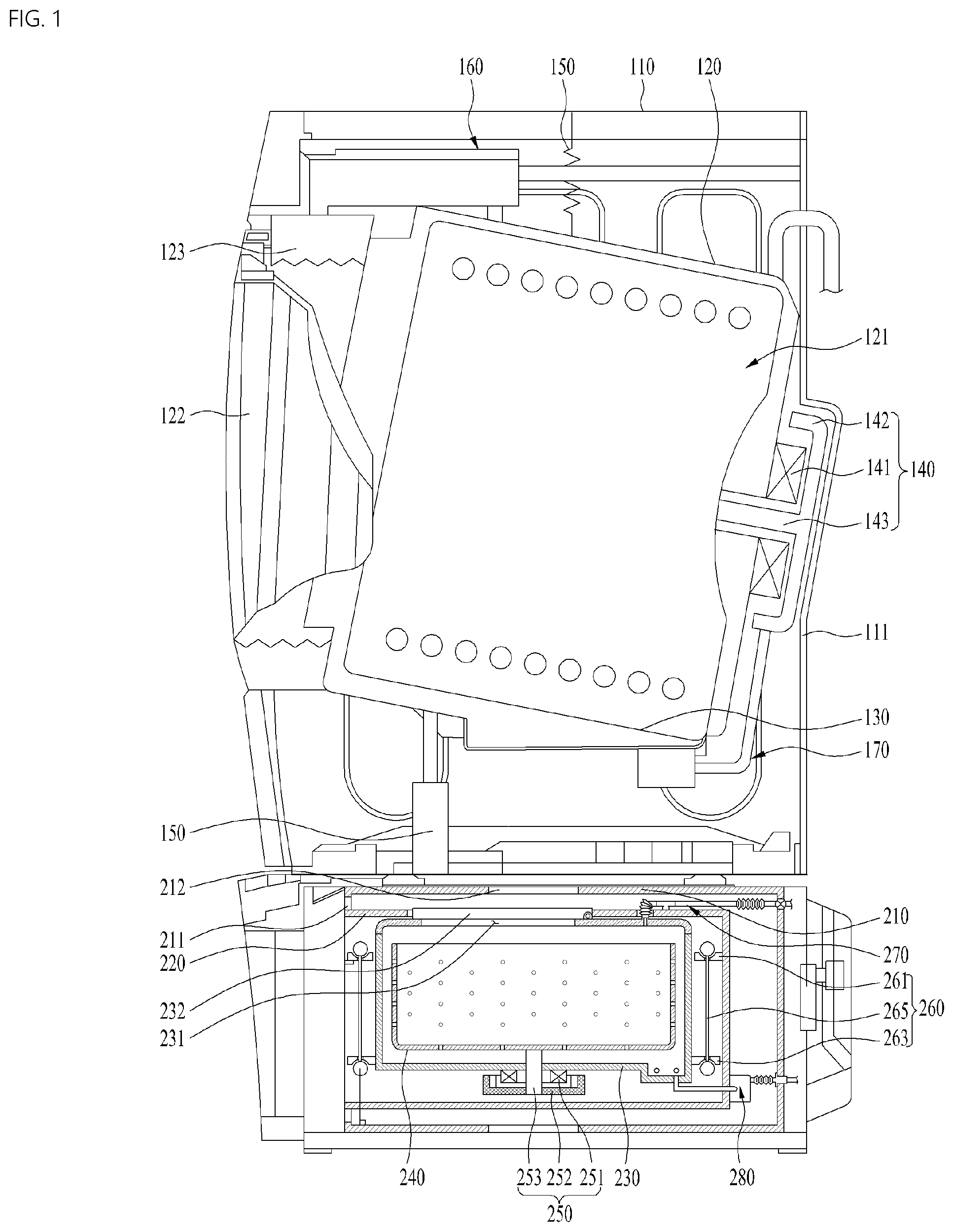
[0069] FIG. 1 shows the basic structure of a first laundry treating apparatus 100 and a second laundry treating apparatus 200 which are to be packaged by the packaging assembly of the present invention.
[0070] The first laundry treating apparatus 100 may be larger than the second laundry treating apparatus 200. Both the first laundry treating apparatus 100 and the second laundry treating apparatus 200 may be provided as washing apparatuses.
[0071] The first laundry treating apparatus 100 may have a larger washing capacity than the second laundry treating apparatus 200, and the second laundry treating apparatus 200 may be provided as an auxiliary laundry treating apparatus for the first laundry treating apparatus 100.
[0072] The second laundry treating apparatus 200 may be arranged under the first laundry treating apparatus 100.
[0073] However, unlike the illustrated example, the second laundry treating apparatus 200 may be arranged at the top of or on a side of the first laundry treating apparatus 100.
[0074] When the second laundry treating apparatus 200 is arranged under the first laundry treating apparatus 100, the second laundry treating apparatus 200 may be provided a drawer type laundry treating apparatus in order to avoid interference with the first laundry treating apparatus 100.
[0075] The first laundry treating apparatus 100 may be provided as a front load type laundry treating apparatus, which has an opening in the front thereof, and the second laundry treating apparatus 200 may be provided as a top load type laundry treating apparatus, which has an opening at the top thereof.
[0076] The first laundry treating apparatus 100 may include a first cabinet 110 defining the appearance thereof, a first tub 120 arranged inside the cabinet 110 to store water, a first drum 130 rotatably arranged in the first tub 120 to accommodate clothes, a first drive unit 140 coupled to the first tub 120 to rotate the first drum 130, a first damper 150 configured to fix the first tub 120 to the first cabinet 110, a first water supply unit 160 configured to supply water to the first tub 120, and a first drainage unit 170 configured to drain water from the first tub 120.
[0077] The first laundry treating apparatus 110 may be provided as a dryer. In this case, the first tub 120 may be omitted and only the first drum 130 may be provided in the first cabinet 110.
[0078] The first cabinet 110 may be provided with an opening in the front thereof, and the first laundry treating apparatus 100 may include a first door 122 configure to open and close an introduction port of the first tub 110 and the opening.
[0079] The first laundry treating apparatus 100 may also include a first gasket 123 configured to seal a gap between the first cabinet 110 and the first tub 120.
[0080] The first water supply unit 160 may include a water supply pipe and a detergent box. The first drainage unit 170 may include a drain pump and a drain pipe. The first water supply unit 160 and the first drainage unit 170 may be formed in any structure as long as they can supply water to the first tub 120 and drain water.
[0081] The first drive unit 140 may include a first stator 141 arranged on the rear surface of the first tub 120 to generate a rotating magnetic field, a first rotor 142 rotated by the first stator 141, a rotary shaft 143 configured to rotate together with the first rotor 142 to rotate the first drum 130.
[0082] The second laundry treating apparatus 200 may be provided as an auxiliary laundry treating apparatus for the first laundry treating apparatus 100 to constitute one set together with the first laundry treating apparatus 100. The second laundry treating apparatus 200 may be formed to have a smaller volume than the first laundry treating apparatus to wash a small amount of clothes.
[0083] The second laundry treating apparatus 200 may include a second cabinet 210 configured to support the first laundry treating apparatus 100 and defining the appearance of the second laundry treating apparatus 200, the second cabinet being provided with a second opening 211 in the front thereof, a drawer 220 arranged inside the second cabinet 210 so as to be drawn out of or inserted into the second opening 211, a second tub 230 arranged inside the drawer 220 to store water, a second drum 240 rotatably arranged inside the second tub 230 to accommodate clothes, a second drive unit 240 coupled to the second tub 230 to rotate the second drum 240, and a second damper 260 configured to fix the second tub 230 to the drawer 220.
[0084] The second laundry treating apparatus 200 may include a second water supply unit 270 configured to supply water to the second tub 230, and a second drainage unit 280 configured to drain water from the second tub 230. The second water supply unit 270 and the second drainage unit 280 may be provided with a flexible tube consider that the drawer 220 is drawn out forward.
[0085] On the other hand, the second laundry treating apparatus 200 may be provided as a dryer. In this case, the second tub 230 may be omitted.
[0086] The second drive unit 240 may include a second stator 241 arranged on a bottom surface of the second tub 230 to generate a rotating magnetic field, a second rotor 242 rotated by the second stator 241, and a second rotary shaft 243 configured to rotate together with the second rotor 242 to rotate the second drum 240.
[0087] The second damper 260 may include a first bracket 261 protruding from the inner peripheral surface of the drawer 220, a second bracket 262 protruding from the outer circumferential surface of the second tub 230 and positioned lower than the first bracket 261, and a connection bar 265 connecting the first bracket 261 and the second bracket 262.
[0088] Hereinafter, at least one of the first tub 120 and the first drum 130 is referred to as a first clothes accommodation part 121, and at least one of the second tub 230 and the second drum 240 is referred to as a second clothes accommodation part 231.
[0089] This is because the same packaging method and structure are used regardless of whether the first cabinet 110 and the second cabinet 210 are provided as washing apparatuses or dryers.
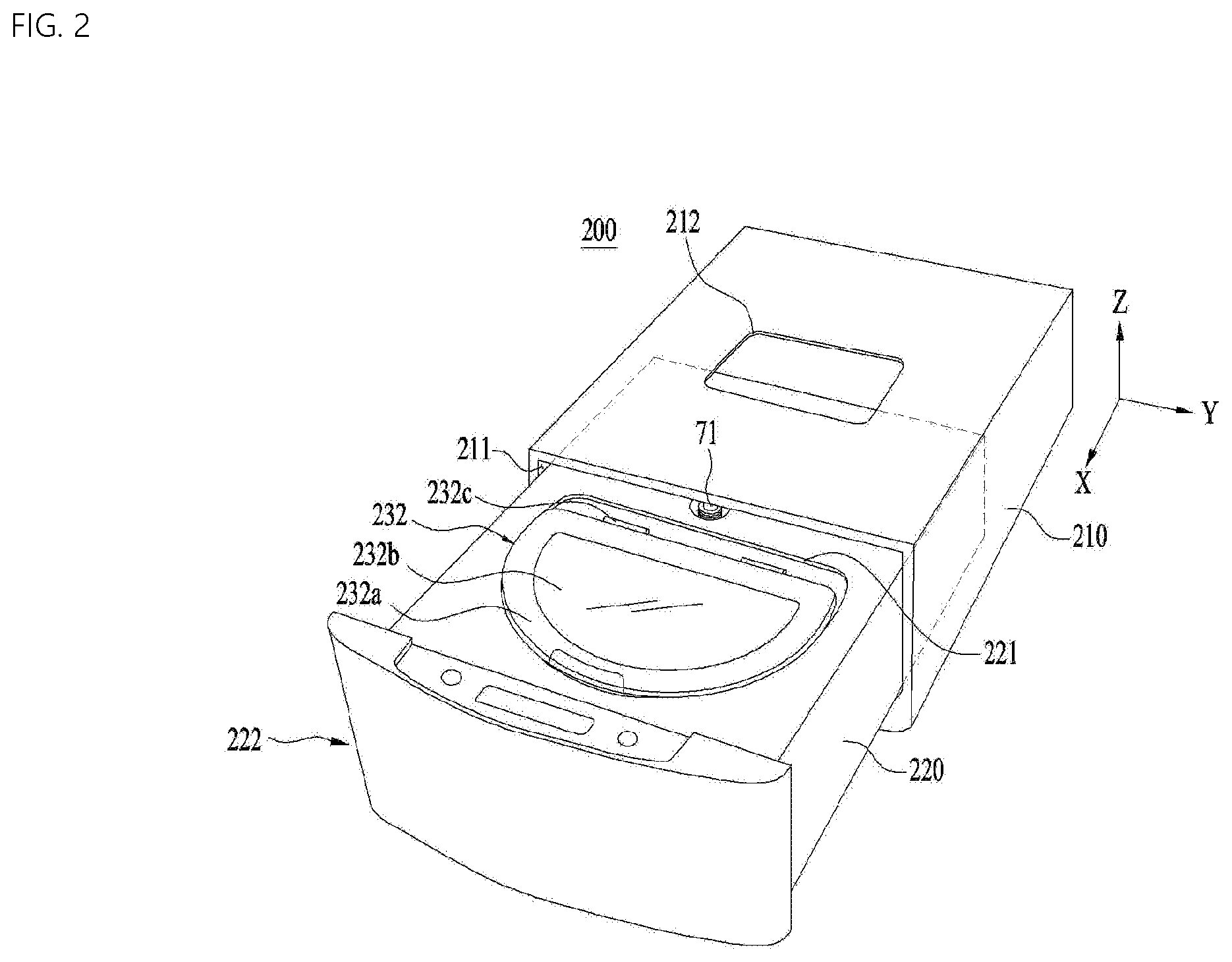
[0090] Referring to FIG. 2, the drawer 220 may be drawn out of the second opening 211 of the second cabinet 210. The drawer 220 may include a drawer panel 222 arranged at the front thereof and formed to be larger than the second opening 211.
[0091] The drawer 220 may be formed in a rectangular parallelepiped shape and provided with an open surface 221 at the top thereof to allow the outside of the drawer 220 to communicate with the second tub 230.
[0092] The second tub 230 may be provided with an introduction port at the top thereof so as to communicate with the open surface 221. The introduction port may be opened and closed by the second door 232.
[0093] The second door 232 may be provided to any one of the drawer 220 or the second tub 230 to open and close the introduction port of the second tub 230.
[0094] The second door 232 may include a frame 232a defining the appearance of the second door 232, a hinge 232c provided at the rear of the frame 232a and having an axis of rotation of the second door 232, and a window 232b provided on an inner surface of the second frame 232a to allow the inside of the second tub 230 to be seen therethrough.
[0095] The second door 232 may be arranged to rotate upward from the second drawer 220 and not to be introduced into the second tub 230.
[0096] That is, the second door 232 may have a larger diameter than the introduction port of the second tub 230.
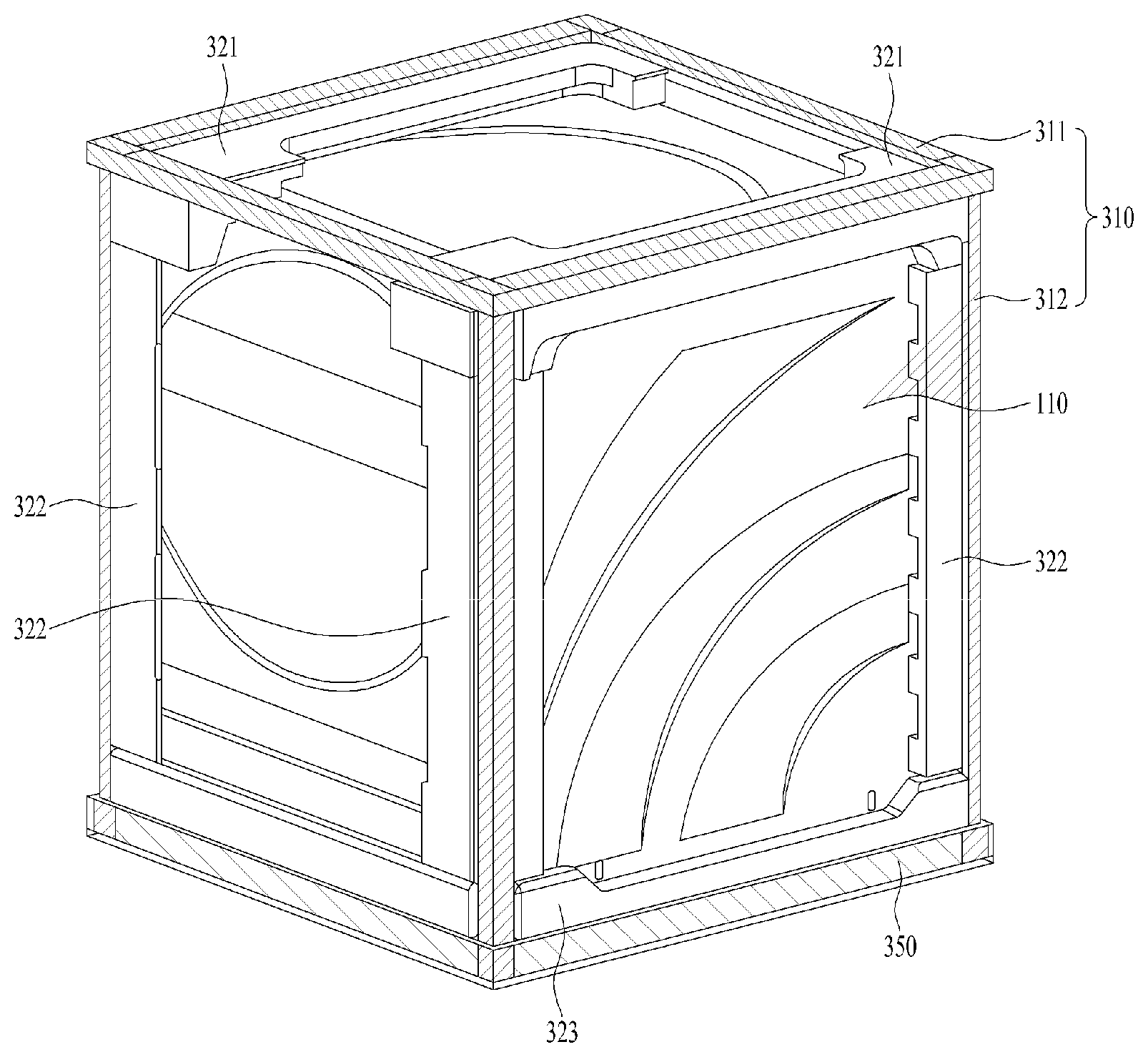
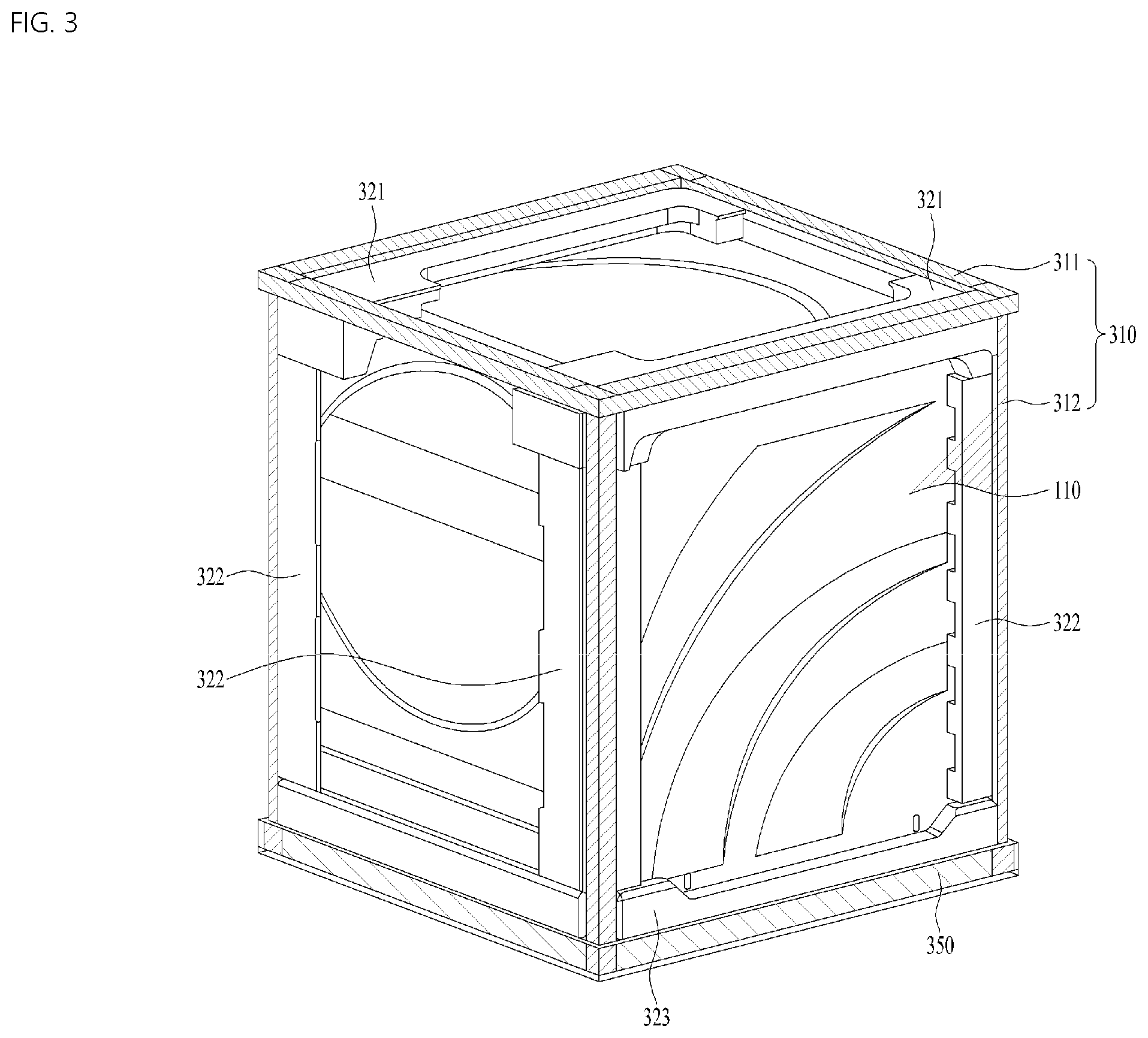
[0097] FIG. 3 shows a structure of a packaging assembly capable of packaging the first laundry treating apparatus and the second laundry treating apparatus as a pair so as to be transported together.
[0098] The packaging assembly of the present invention include a support part 300 configured to seat and support one of the first cabinet 110 and the second cabinet 210 on the other one of the first cabinet 110 and the first cabinet 110. The packaging assembly may be configured to transport the first cabinet 110 and the second cabinet 210 at a time.
[0099] The support part 300 may include a support frame 310 configured to accommodate the first cabinet 110 and support the second cabinet 210 arranged thereon.
[0100] The support frame 310 may be provided as a rigid body capable of maintaining a certain shape.
[0101] The second cabinet 210 may be disposed on the support frame 310 (see FIG. 5). The first cabinet 110 may be disposed inside the support frame 310 so as not to collide with or contact the second cabinet 210.
[0102] Since the support frame 310 has its own thickness, the second cabinet 210 is unlikely to collide with or contact the first cabinet 110 even when it is brought into contact with or seated on the top surface of the first cabinet 110.
[0103] In addition, even if the packaging assembly 300 overturns or falls while the first cabinet 110 and the second cabinet 210 are transported together with the support frame 310, most of the shock may be absorbed by the support frame 310, and the support frame 310 may prevent the first cabinet 110 and the second cabinet 210 from colliding with each other.
[0104] The support frame 310 may be formed of a brittle material in consideration of shock absorption.
[0105] Thus, the support frame 310 may be formed of a wood material. When the support frame 310 is provided with a material such as wood, it may have rigidity high enough to support the second frame 210 and may be broken when subjected to impact. Accordingly, the support frame may minimize damage to the first cabinet 110 and the second cabinet 210 when the assembly is dropped or overturned.
[0106] In order to prevent shock applied to the support frame 310 from being transmitted to the first cabinet 110, the support frame 310 may be formed to occupy a larger volume than the first cabinet 110.
[0107] The support frame 310 may include an upper frame 311 spaced apart from a top surface of the first cabinet 110 by a predetermined distance, and a plurality of side frames 312 extending from each vertex of the upper frame 110 toward the bottom surface of the first cabinet 110.
[0108] The upper frame 311 may be formed to correspond to the shape of the upper surface of the first cabinet 110. For example, the upper frame 310 may have a rectangular shape.
[0109] The side frames 312 may be integrated with the upper frame 311, and may be longer than the height of the first cabinet 110. Accordingly, the side frames 312 may keep the upper frame 311 spaced apart from the top surface of the first cabinet 110.
[0110] The support frame 310 may have a shape obtained by enlarging the shape of the first cabinet 110 at a predetermined ratio.
[0111] Accordingly, when the assembly overturns or falls, the support frame 310 may not transmit a shock applied directly thereto to the first cabinet 110.
[0112] In addition, the support frame 310 may not have a separate frame at the bottom thereof. The side frame 312 have an upper end connected to the upper frame 311, and a lower end configured as a free end. Accordingly, when the packaging assembly 300 overturns or falls, the side frame 312 may be spread or broken in all directions, thereby absorbing most of the shock applied thereto.
[0113] The packaging assembly 300 of the present invention may further include a shock absorption member 320 detachably provided at a corner of the first cabinet 110 to absorb shock.
[0114] The shock absorption member 320 may be arranged to fill the space between the support frame 310 and the first cabinet 110 and to support the support frame 310 to maintain the shape of the support frame 310.
[0115] In addition, when the support frame 310 overturns or falls, or when external shock is transmitted to the support frame 310, the shock absorption member may absorb shock to protect the first cabinet 110.
[0116] The shock absorption member 320 may be formed of a material capable of absorbing external shock. For example, it may be formed of polystyrene or a porous material.
[0117] The shock absorption member 320 may include an upper shock absorption member 321 detachably provided to a corner of the top surface of the first cabinet 110 to support the upper frame 311, and a side shock absorption member 322 detachably provided to a corner of side surfaces of the first cabinet 110 so as to contact the side frames.
[0118] Since the side shock absorption member is detachably provided to the first cabinet 110, the side shock absorption member may include a plurality of side shock absorption members, and the upper shock absorption member 321 may be detachably arranged on the top surface of the first cabinet 110.
[0119] However, the upper shock absorption members 321 may be provided to one corner of the first cabinet 110 and an opposite corner facing the one corner of the first cabinet 110, rather than covering the entire top surface of the first cabinet 110. That is, the upper shock absorption member 321 may be detachably arranged only at corners of the first cabinet 110 facing each other such the top surface of the first cabinet 110 is exposed as much as possible.
[0120] Thereby, the load of the second cabinet 210 is transferred to the top surface of the first cabinet 110, the top surface of the first cabinet 110 may be bent downward. In addition, since the top surface of the first cabinet 110 is supported by a side panel defining the side surface of the first cabinet 110, it has sufficient rigidity and thus may withstand the load of the second cabinet 210 applied thereto.
[0121] The side shock absorption members 322 may be separated from each other and provided to the respective corners of the first cabinet 110. Accordingly, the side shock absorption members 322 may be easily detached from the first cabinet 110.
[0122] At least a part of the second cabinet 210 may be seated on the top surface of the upper shock absorption member 321. In the case where the second cabinet 210 is packaged in a separate packaging member 301, a part of the packaging member 301 of the second cabinet 210 may be seated on the top surface.
[0123] As a result, the load of the second cabinet 210 may be distributed by the support frame 310 and the shock absorption member 320.
[0124] The shock absorption member 320 may further include a lower shock absorption member 323 arranged on the bottom surface of the first cabinet 110 to support the first cabinet 110 and the side shock absorption members 322.
[0125] The side shock absorption member 322 may be arranged between the upper shock absorption member 312 and the lower shock absorption member 323. The lower shock absorption member 323 by supporting the side shock absorption member 322 the upper shock absorption member 312 by supporting the side shock absorption member 322.
[0126] The lower shock absorption member 323 may include an accommodation groove 323b formed on the top surface thereof to accommodate a lower portion of the first cabinet 110 (see FIG. 4).
[0127] The accommodation groove 323b may be formed such that the depth thereof is less than the thickness of the lower shock absorption member 323. This is intended to prevent the bottom surface of the first cabinet 110 from directly contacting the ground.
[0128] At least a part of the first cabinet 110 may be press-fitted into the accommodation groove 323b.
[0129] Even when the entire packaging assembly 300 falls with the first cabinet 110 and the second cabinet 210 packaged therein, the lower shock absorption member 323 may absorb shock, thereby protecting the second cabinet 210 as well as the first cabinet 110.
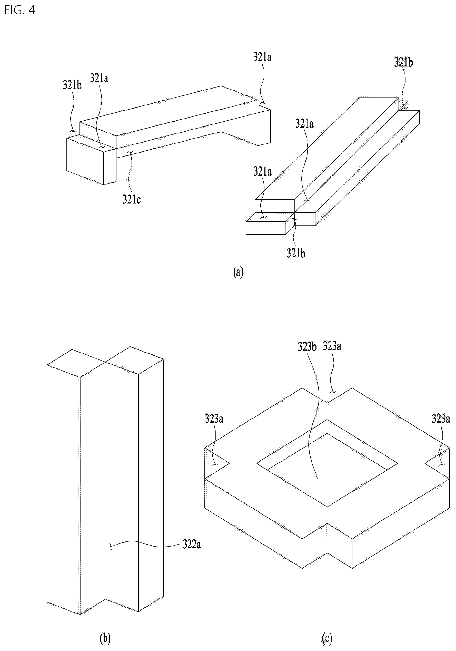
[0130] FIG. 4 shows a specific configuration of the shock absorption member 320.
[0131] Referring to FIG. 4(a), the upper shock absorption member 321 may include an upper groove 321a, 321b to accommodate one of the upper frame 311 and the side frame 312 at each corner.
[0132] The upper groove may include a first groove 321a defined by one stepped corner of the upper shock absorption member to accommodate the upper frame 311, and a second groove 321b defined by a stepped corner adjacent to opposite ends of the one corner to accommodate the side frame 312.
[0133] The support frame 310 may be seated and supported in the first groove 321a and the second groove 321b of the upper shock absorption member 321. In addition, the support frame 310 may be press-fitted into the upper shock absorption member 321.
[0134] Thereby, adhesion or close contact between the support frame 310 and the upper shock absorption member 321 may be maximized, and the upper shock absorption member 321 may be prevented from being separated from the support frame 310 even when an external shock is applied thereto.
[0135] In addition, the other portion of the upper shock absorption member 321 than the first groove 321a and the second groove 321b may be parallel to the support frame 310 or protrude to the outside of the support frame 310.
[0136] Accordingly, even when another packaging assembly or other home appliance outside the support frame 310 collides with the packaging assembly in which the first packaging 110 and the second cabinet 210 are packaged, the upper shock absorption member 321 may absorb the shock.
[0137] In addition, the top surface of the upper shock absorption member 321 may be arranged parallel to the upper end of the support frame 310, and accordingly it may support the second cabinet 210.
[0138] Referring to FIG. 4(b), the side shock absorption member 322 may include a side groove 322a defined by a stepped corner of the side shock absorption member positioned farthest from the first cabinet, the side groove accommodating the side frame 312.
[0139] That is, the side shock absorption member 322 may be fixed to the side frame 312 and thus may not be separated. Thus, coupling or close contact with the side frame 312 may be maximized.
[0140] In addition, the side shock absorption member 322 may be arranged parallel to the outermost surface of the side frame 312 or protrude from the outermost surface to absorb any external shock.
[0141] The side frame 312 may extend up to the lower end of the packaging assembly 300. The side frame 312 may extend from the upper frame 311 to the lower end of the lower shock absorption member 323 beyond the bottom of the first cabinet 110.
[0142] This is intended to make the side frame 312 positioned as close to the ground as possible to maximize supportability.
[0143] Referring to FIG. 4(c), the lower shock absorption member 323 may include a lower groove 323a for accommodating the side frame 312 at each corner.
[0144] The lower groove 323a may not only prevent the side frame 312 and the lower shock absorption member 323 from interfering with each other, but also improve close contact with the lower shock absorption member 323, thereby enhancing durability of the side frame 312.
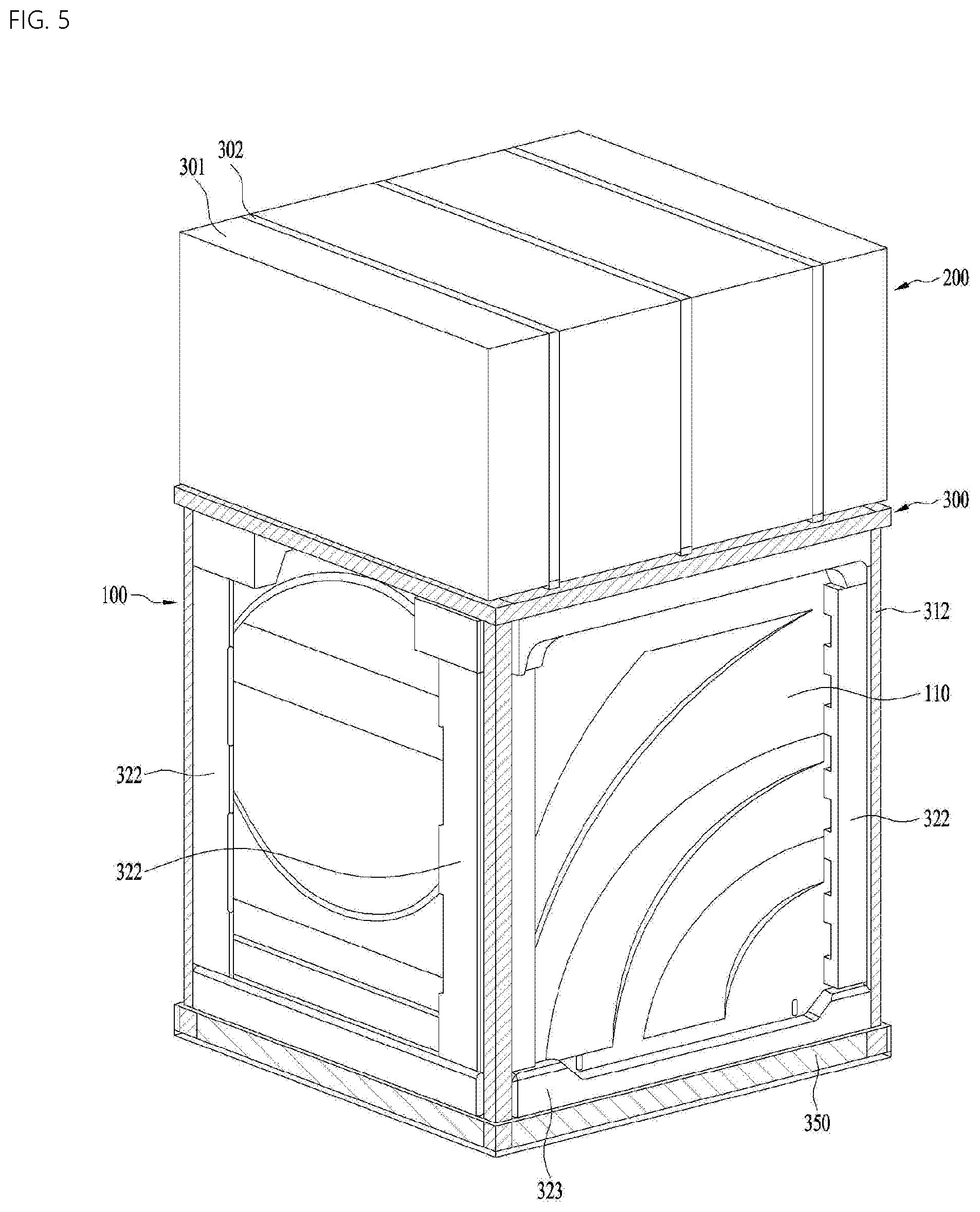
[0145] FIG. 5 shows a packaging assembly 300 arranging to be integrally package and transport the first cabinet 110 and the second cabinet 210, which is seated on the support part 300.
[0146] The second cabinet 210 may be supported by at least one of the upper frame 311 or the upper shock absorption member 321. Accordingly, even when the packaging assembly 300 is dropped, shock may not be transmitted to the second cabinet 210, and the second cabinet 210 may be prevented from colliding with the first cabinet 110.
[0147] Since the side frame 312 is connected only to the upper frame 311, the lower end of the side frame 312 is provided as a free end.
[0148] Thereby, the side frame 312 is allowed to move relatively freely. Accordingly, when the assembly overturns or falls, the side frame 312 may absorb the shock applied to the packaging assembly 300 as it spreads out, is separated from the upper frame 311, or is broken.
[0149] However, since the side frame 312 is not fixed, the lower shock absorption member 323 may be damaged, and it may be difficult to transport and store the packaging assembly 300.
[0150] To address this issue, the packaging assembly 300 of the present invention may further include a lower accommodation part 350 configured to accommodate a lower portion of the first cabinet 110 and to support the lower ends of the plurality of side frames.
[0151] When the lower shock absorption member 323 is not provided, the lower accommodation part 350 may accommodate the lower portion of the first cabinet 110. When the lower shock absorption member 323 is provided, the lower accommodation part may accommodate the lower shock absorption member 323, thereby accommodating the lower portion of the first cabinet 110.
[0152] The lower accommodation part 350 may be formed as a recess. The lower shock absorption member 323 may be press-fitted into the recess. The lower accommodation part 350 may serve to fix the lower ends of the side frames 312 in cooperation with the lower grooves 323a to fix the side frames 312.
[0153] The lower accommodation part 350 may be formed of a material having higher brittleness than the support frame 310. For example, the lower accommodation part 350 may be formed of plastics, and may be arranged in a corrugated cardboard shape to absorb external shock.
[0154] Accordingly, when the packaging assembly 300 falls, the lower accommodation part 350 may be damaged such that the side frames 312 can be freely deformed or broken to absorb shock.
[0155] The second cabinet 210 may be separately packaged with a separate packaging member 301 and a packing band 302 for fixing the packaging member to prevent damage to the appearance of the second cabinet.
[0156] FIG. 6 shows 6 the final form of the packaging assembly 300.
[0157] The first cabinet 110 and the shock absorption part 320 may be accommodated in the support frame 310, and the second cabinet 210 may be seated on the support frame 310. Then, the packaging assembly 300 may be wrapped with the packaging member 303 as a whole.
[0158] Thereafter, the packaging member 323 may be fixed by a plurality of bands 304 for fixing the same. Thereby, the second cabinet 210 may be prevented from being separated from the support frame 310.
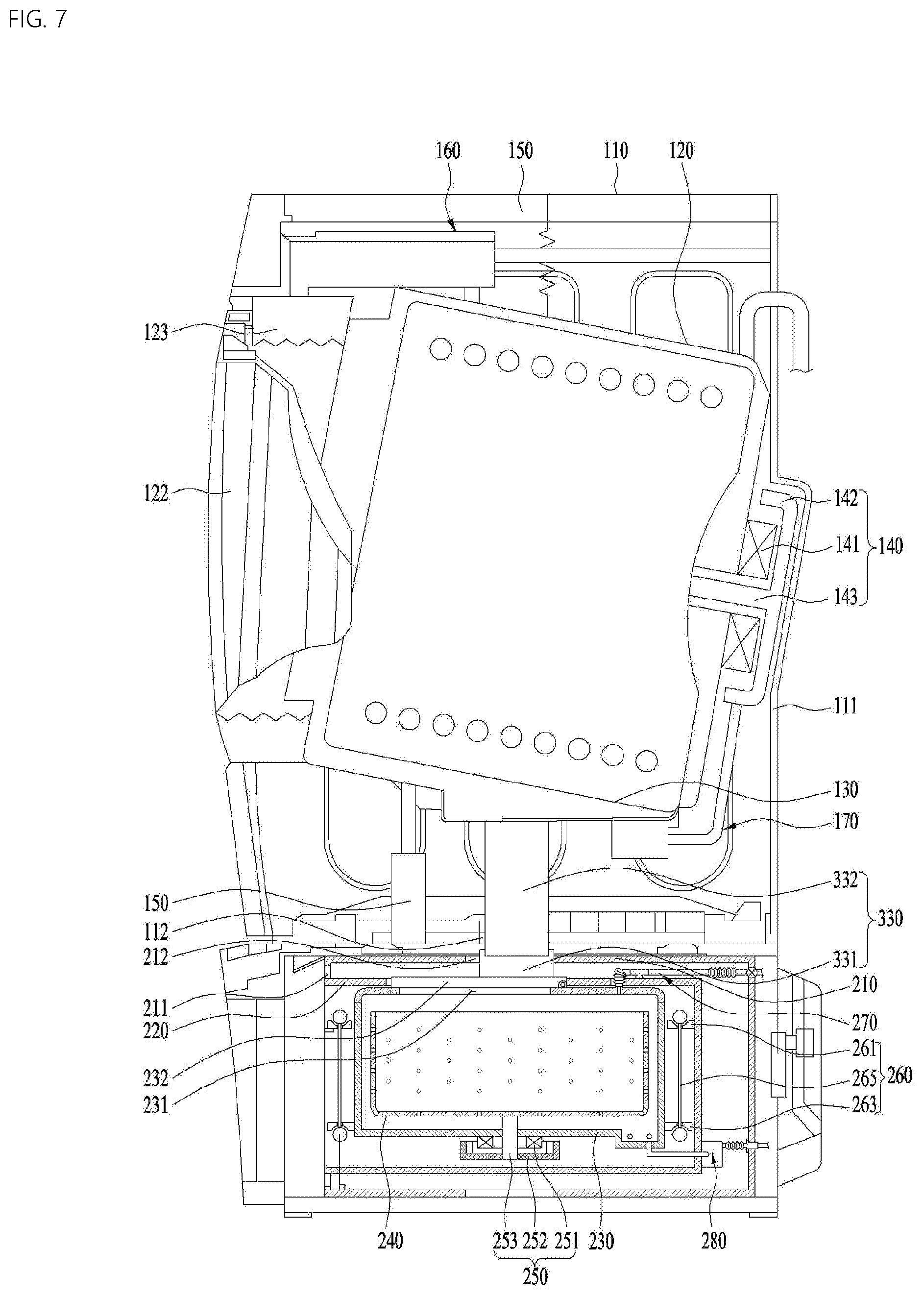
[0159] FIG. 7 shows another embodiment of the packaging assembly according to the present invention.
[0160] Since the first cabinet 110 is larger and heavier than the second cabinet 210, the first cabinet 110 may be arranged in a lower portion of the support frame 310.
[0161] However, in the case where the support part 300 is provided with the support frame 310, the user or seller may need to remove the package and switch the positions of the second cabinet 210 and the first cabinet 110.
[0162] Therefore, arranging the first cabinet 110 and the second cabinet 210 in position for actual use and packaging the same at a time may be considered. That is, the first cabinet 110 and the second cabinet 210 need to be packaged or transported with the second cabinet 210 seated on the first cabinet 110.
[0163] However, when the first cabinet 110 and the second cabinet 210 are integrally arranged and transported, the overall center of gravity thereof may be shifted upward because the first cabinet 110 may has a larger volume. When vibration is caused during transportation of the packaging assembly in which the second cabinet 210 and the first cabinet 110 seated thereon are packaged, the first clothes accommodation part 121 will vibrate. When the first clothes accommodation part 121 vibrates, the overall amplitude may severely increase because most of the vibration occurs at a high position where the center of gravity is placed.
[0164] As a result, there is a risk that the first cabinet 110 is dropped or is separated from the second cabinet 210.
[0165] In addition, when the second clothes accommodation part 231 provided in the second cabinet 210 vibrates, the vibration may be transmitted to the first cabinet 110, and the first clothes accommodation part 121 may vibrate, increasing the overall amplitude.
[0166] Therefore, the first clothes accommodation part 121 and the second clothes accommodation part 231 need to be prevented from being vibrated during transportation.
[0167] Referring to FIG. 7, the support part 300 of the packaging assembly of the present invention may include a fixing part 330 configured to support the first clothes accommodation part 121 seated on the top surface of the second cabinet 210 and arranged inside the first cabinet 110.
[0168] The packaging assembly may further include a shock absorption member (see FIG. 9), a packaging member (not shown) and a band (not shown), which are arranged outside the first cabinet 110 and the second cabinet 210, as well as the fixing part 330.
[0169] The fixing part 330 may support the first clothes accommodation part 121 arranged inside the first cabinet 110 to prevent the first clothes accommodation part 121 from vibrating. Even when the first clothes accommodation part 121 vibrates, the fixing part 330 may dampen or attenuate the vibration.
[0170] To this end, the first cabinet 110 may include a lower through hole 112 through which the fixing part 330 is inserted into the bottom surface. The second cabinet 210 may include an upper through hole 212 formed in the top surface thereof, and the fixing part 330 may be supported on the top surface of the second clothes accommodation part 231.
[0171] That is, the fixing part 330 may be supported on the top surface of the second clothes accommodation part 231 to support the bottom surface of the first clothes accommodation part 121.
[0172] Thereby, the fixing part 330 may prevent the second clothes accommodation part 231 from vibrating or being displaced, and also prevent the first clothes accommodation part 121 from vibrating.
[0173] Therefore, the first cabinet 110 may be prevented from overturning even when the second cabinet 210 and the first cabinet 110 seated on the top surface thereof are packaged and transported.
[0174] In addition, the fixing part 330 may prevent the first clothes accommodation part 121 and the second clothes accommodation part 231 from colliding with the first cabinet 110 and the second cabinet 210.
[0175] The fixing part 330 may ensure that the second cabinet 210 and the first cabinet 110 seated on the top surface thereof are stably packaged or transported.
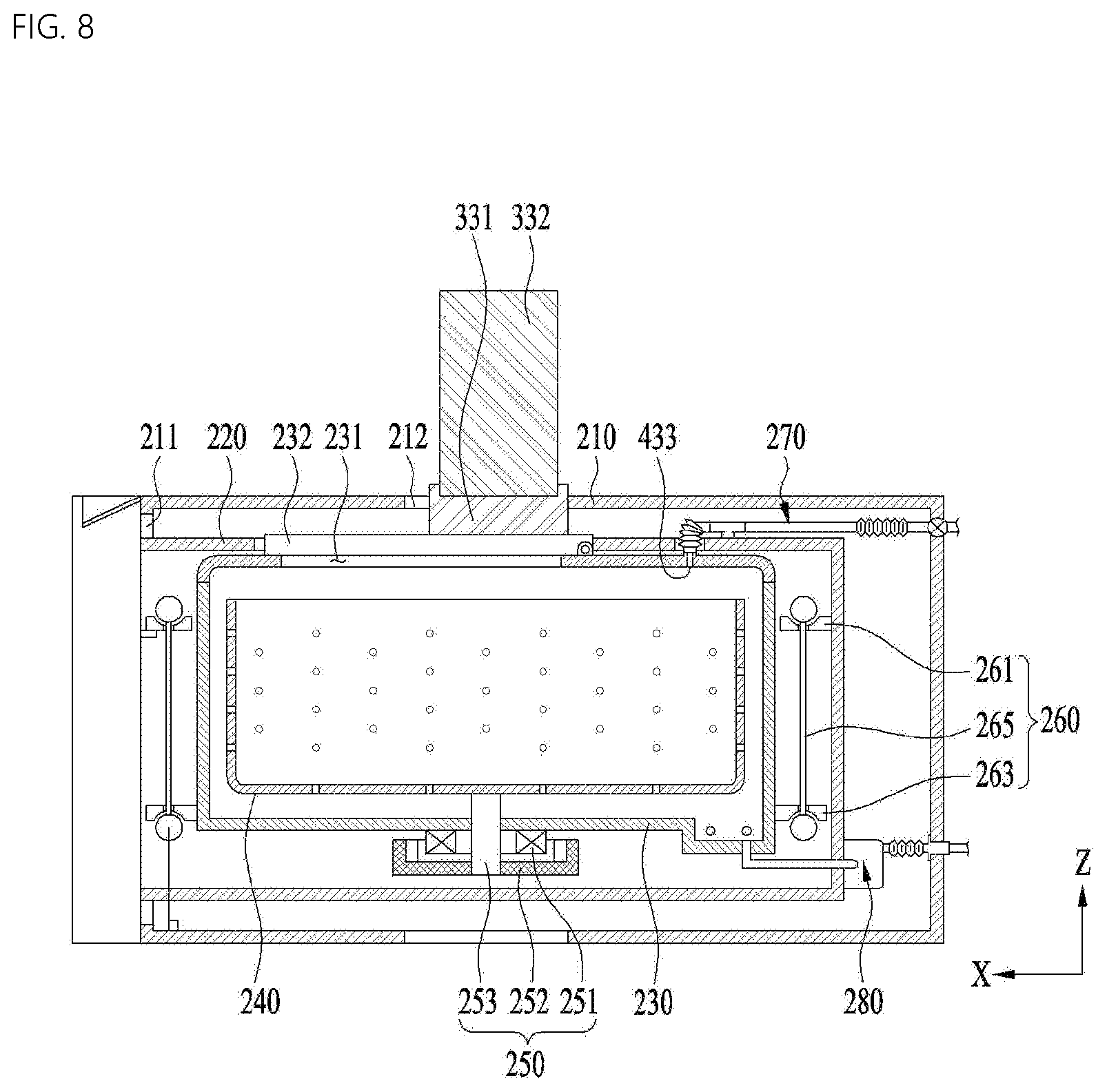
[0176] FIG. 8 illustrates coupling between the second cabinet 210 and the fixing part 330.
[0177] Referring to FIG. 8, a lower end of the fixing part 330 may be seated on and supported by the top surface of the second door 232 of the second clothes accommodation part 231. Specifically, the lower end of the fixing part 330 may be supported by the window 232b of the second door 232.
[0178] Since the fixing part 330 can push the second clothes accommodation part 231 downward, the first bracket 261 and the second bracket 263 may be maintained from the connection bar 265 as far from each other as possible.
[0179] Thereby, the second clothes accommodation part 231 may be prevented from being displaced or vibrating in the drawer 220 or the second cabinet 210.
[0180] When the fixing part 330 is arranged to protrude from the second cabinet 210, it may be difficult to seat the first cabinet 110 on the second cabinet 210.
[0181] Therefore, in order to address this issue, the fixing part 330 may include a closing fixing part 331 arranged on the top surface of the second clothes accommodation part 231 so as to be parallel to the upper through hole 212 to close the upper through hole 212, and a supporting fixing part 332 separately coupled to an upper portion of the closing fixing part 331 to support the first clothes accommodation part 121.
[0182] Thus, as the closing fixing part 331 is first installed on the second cabinet 210, the first cabinet 110 is seated, and then the supporting fixing part 332 is additionally coupled to an upper portion of the closing fixing part 331, the packaging assembly may be completed.
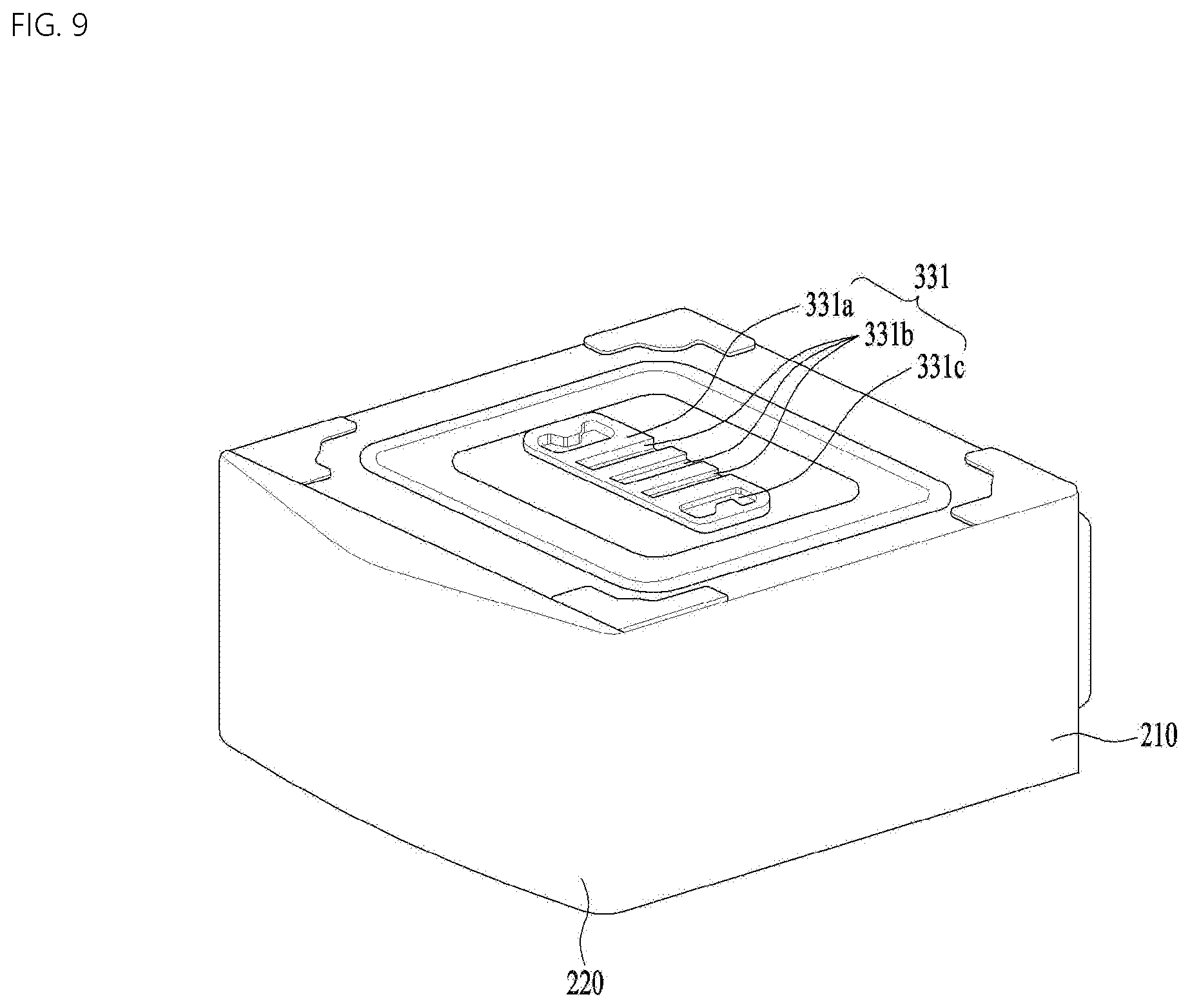
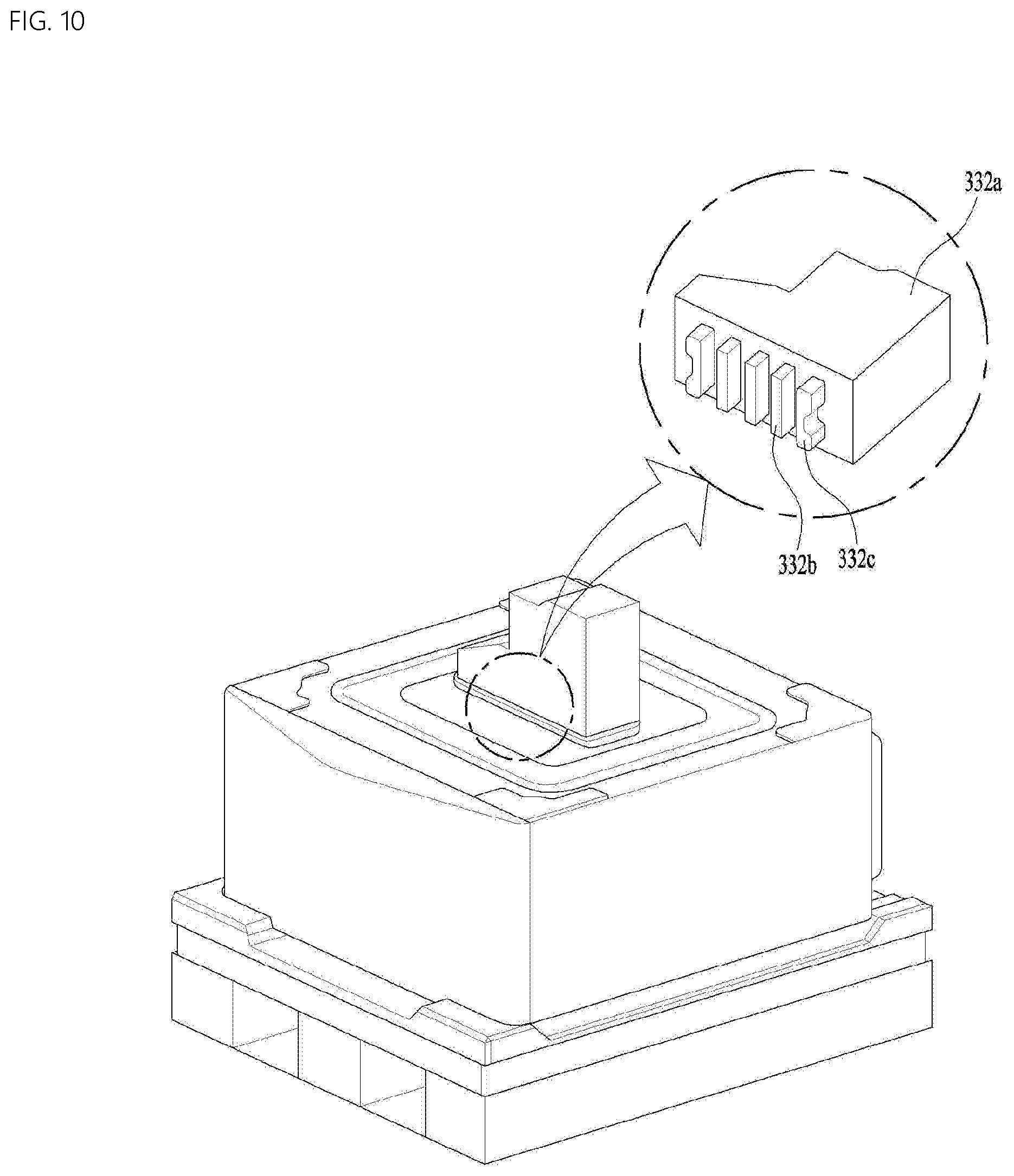
[0183] FIGS. 9 and 10 illustrate coupling between the closing fixing part 331 and the supporting fixing part 332.
[0184] The closing fixing part 331 may include a closing body 331a supported on the top surface of the second clothes accommodation part 231 to close the upper through-hole 212, a slide groove 331b formed in the top surface of the closing body 331a to guide a coupling position of the supporting fixing part 332, and a coupling groove 331c formed in the top surface of the closing body 331a and coupled with the supporting fixing part 332 to fix the supporting fixing part 332.
[0185] The supporting fixing part 332 may include a fixing body 332a fixed to the closing fixing part 331 to support the first clothes accommodation part 121, a slide rib 332b protruding from the fixing body 332a so as to slide in the slide groove 331b, and a coupling protrusion 332c protruding from the fixing body 332a so as to be inserted into the coupling groove 331c and coupled thereto.
[0186] One of the coupling protrusion 332c and the coupling groove 331c may be provided as a magnetic force generator for generating a magnetic field, and the other of the coupling protrusion 332c and the coupling groove 331c may be provided as a magnetic member to be magnetized by the magnetic field of the magnetic force generator.
[0187] Thus, even when the supporting fixing part 332 is subjected to external force or vibration, it may be prevented from being separated from the closing fixing part 331.
[0188] FIG. 11 illustrates a method and procedure of removing the fixing part 300 from the packaging assembly.
[0189] The first cabinet 110 may further include a rear panel 111 defining a rear surface of the first cabinet 110 and detachably provided to the first cabinet 110.
[0190] Referring to FIG. 11(a), when transportation of the first cabinet 110 and the second cabinet 210 is completed, the rear panel 111 of the first cabinet 110 is separated.
[0191] Referring to FIG. 11(b), the supporting fixing part 332 is separated from the closing fixing part 331 and drawn out through the rear of the first cabinet 110.
[0192] Referring to FIG. 11(c), the closing fixing part 331 may be drawn out through the rear of the first cabinet 110 via the upper through hole 212.
[0193] Referring to FIG. 11(d), since the fixing part 330 is completely removed, the rear panel 111 may be coupled to the first cabinet 110 again.
[0194] When the first cabinet 110 and the second cabinet 210 are transported or packaging again, the operations described above may be performed in reverse order.
[0195] The present invention may be embodied in various forms without departing from the scope of the invention. Accordingly, it is intended that the present invention cover the modifications and variations of this invention provided they come within the scope of the appended claims and their equivalents.
* * * * *
D00000
D00001
D00002
D00003
D00004
D00005
D00006
D00007
D00008
D00009
D00010
D00011
XML
uspto.report is an independent third-party trademark research tool that is not affiliated, endorsed, or sponsored by the United States Patent and Trademark Office (USPTO) or any other governmental organization. The information provided by uspto.report is based on publicly available data at the time of writing and is intended for informational purposes only.
While we strive to provide accurate and up-to-date information, we do not guarantee the accuracy, completeness, reliability, or suitability of the information displayed on this site. The use of this site is at your own risk. Any reliance you place on such information is therefore strictly at your own risk.
All official trademark data, including owner information, should be verified by visiting the official USPTO website at www.uspto.gov. This site is not intended to replace professional legal advice and should not be used as a substitute for consulting with a legal professional who is knowledgeable about trademark law.