Scaling And Corrosion Resistant Fluid Conduit
Kool; Lawrence Bernard ; et al.
U.S. patent application number 16/465066 was filed with the patent office on 2019-12-19 for scaling and corrosion resistant fluid conduit. The applicant listed for this patent is Aramco Services Company, Hai CHANG, Xubin GAO, General Electric Company, Lawrence Bernard KOOL, Limin WANG, Dalong ZHONG, Hui ZHU. Invention is credited to Hai Chang, Xubin Gao, Lawrence Bernard Kool, Limin Wang, Dalong Zhong, Hui Zhu.
| Application Number | 20190382898 16/465066 |
| Document ID | / |
| Family ID | 62241132 |
| Filed Date | 2019-12-19 |


| United States Patent Application | 20190382898 |
| Kind Code | A1 |
| Kool; Lawrence Bernard ; et al. | December 19, 2019 |
SCALING AND CORROSION RESISTANT FLUID CONDUIT
Abstract
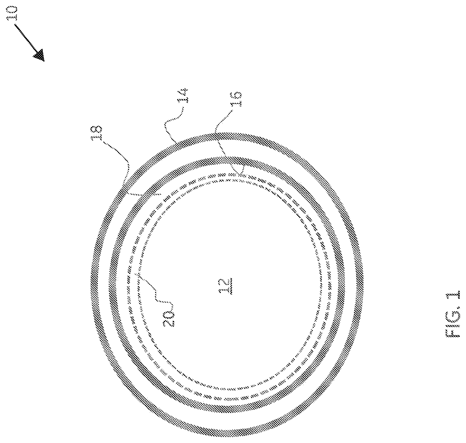
A fluid conduit (10) is provided having (a) a fluid conduit exterior surface (14); (b) a fluid conduit interior surface (16); (c) an electroless nickel protective coating (18) disposed upon one or both of the fluid conduit interior surface and the fluid conduit exterior surface; and (d) a layer (20) of Ni.sub.3S.sub.2 disposed upon and substantially covering the electroless nickel protective coating. The fluid conduit can be any fluid conduit through which a fluid may be caused to pass, such as a downhole tubular used in oil and gas production, or a gas liquid cyclonic separator. And a hydrocarbon production tube, a method of producing a fluid conduit comprising a nickel sulfide protective layer, a machine component comprising at least one surface having a protective outer layer are provided. The combination of the electroless nickel inner protective coating with an outer layer of Ni.sub.3S.sub.2 affords articles such as fluid conduits and machine components with exceptional scale and corrosion resistance.
| Inventors: | Kool; Lawrence Bernard; (Niskayuna, NY) ; Gao; Xubin; (Shanghai, CN) ; Zhu; Hui; (Shanghai, CN) ; Wang; Limin; (Marlborough, MA) ; Chang; Hai; (Shanghai, CN) ; Zhong; Dalong; (Shanghai, CN) | ||||||||||
| Applicant: |
|
||||||||||
|---|---|---|---|---|---|---|---|---|---|---|---|
| Family ID: | 62241132 | ||||||||||
| Appl. No.: | 16/465066 | ||||||||||
| Filed: | November 30, 2016 | ||||||||||
| PCT Filed: | November 30, 2016 | ||||||||||
| PCT NO: | PCT/CN2016/107912 | ||||||||||
| 371 Date: | May 29, 2019 |
| Current U.S. Class: | 1/1 |
| Current CPC Class: | C23C 18/1662 20130101; C23C 18/36 20130101; C23C 28/322 20130101; C23C 18/32 20130101; C23C 18/165 20130101; C23C 28/34 20130101 |
| International Class: | C23C 18/36 20060101 C23C018/36; C23C 18/16 20060101 C23C018/16; C23C 28/00 20060101 C23C028/00 |
Claims
1. A fluid conduit, the fluid conduit defining an interior volume and comprising: (a) a fluid conduit exterior surface; (b) a fluid conduit interior surface; (c) an electroless nickel protective coating disposed upon at least one of the fluid conduit interior surface and the fluid conduit exterior surface; and (d) a layer of Ni.sub.3S.sub.2 disposed upon and substantially covering the electroless nickel protective coating.
2. The fluid conduit according to claim 1, wherein the layer of Ni.sub.3S.sub.2 is characterized by an average thickness in a range from about 1 to about 100 microns and hermetically isolates the electroless nickel protective coating from the fluid conduit interior volume.
3. The fluid conduit according to claim 1, wherein the layer of Ni.sub.3S.sub.2 is characterized by one or more morphologies selected from the group consisting of one or more nanosheet morphologies, one or more nanowire morphologies, one or more rod-like morphologies, one or more block-like morphologies, and combinations of two or more of the foregoing morphologies.
4. The fluid conduit according to claim 1, wherein the layer of Ni.sub.3S.sub.2 is characterized principally by one of i) one or more nanosheet morphologies, ii) one or more nanowire morphologies, iii) one or more rod-like morphologies, and iv) one or more block-like morphologies.
5-7. (canceled)
8. The fluid conduit according to claim 1, wherein the electroless nickel protective coating is configured as a bilayer coating comprising an inner electroless nickel bond layer comprising from about to about 20% by weight phosphorous based on a total weight of the electroless nickel bond layer, and an electroless nickel outer layer comprising hard particles selected from the group consisting of diamond, silicon carbide, boron nitride, talc, and combinations of two or more of the foregoing.
9. The fluid conduit according to claim 8, wherein the hard particles are present in a range from about 10 to about 40 percent by weight based on the total weight of the electroless nickel outer layer.
10. The fluid conduit according to claim 1, wherein a metallurgical bond is formed between the fluid conduit interior surface and the electroless nickel protective coating.
11. The fluid conduit according to claim 1, wherein the fluid conduit is selected from the group consisting of production tubing, valves, storage vessels, reaction vessels, surface pipelines, subsea pipelines, cyclonic separators, wellheads, manifolds, blowout preventers, Christmas trees, and exhaust gas conduits.
12. The fluid conduit according to claim 1, wherein the fluid conduit is a tube for transporting a hydrocarbon production fluid.
13-21. (canceled)
22. A method of producing a fluid conduit comprising a nickel sulfide protective layer, the method comprising: (a) heating a fluid conduit comprising an electroless nickel protective coating disposed upon a surface of the fluid conduit in contact with a fluid comprising hydrogen sulfide; and (b) depositing a protective layer of Ni.sub.3S.sub.2 upon and substantially covering the electroless nickel protective coating.
23. The method of claim 22, wherein said heating is carried at one or more temperatures in a range from about 100 to about 400 degrees centigrade.
24. The method according to claim 22, wherein the protective layer of Ni.sub.3S.sub.2 is characterized by an average thickness in a range from about 1 to about 100 microns and hermetically isolates the electroless nickel protective coating.
25. The method according to claim 22, wherein said fluid comprising hydrogen sulfide further comprises water.
26. The method according to claim 22, further comprising a post deposition annealing step which converts an initial Ni.sub.3S.sub.2 morphology into an alternate Ni.sub.3S.sub.2 morphology.
27. A machine component comprising at least one surface having a protective outer layer, the protective outer layer comprising: (a) an inner electroless nickel coating; and (b) a layer of Ni.sub.3S.sub.2 disposed upon and substantially covering the electroless nickel coating.
28. (canceled)
29. The machine component according to claim 27, wherein the layer of Ni.sub.3S.sub.2 is characterized by one or more morphologies selected from the group consisting of one or more nanosheet morphologies, one or more nanowire morphologies, one or more rod-like morphologies, one or more block-like morphologies, and combinations of two or more of the foregoing morphologies.
30. The machine component according to claim 27, wherein the layer of Ni.sub.3S.sub.2 is characterized principally by one of i) one or more nanosheet morphologies, ii) one or more nanowire morphologies, iii) one or more rod-like morphologies, and iv) one or more block-like morphologies.
31-33. (canceled)
34. The machine component according to claim 27, wherein the electroless nickel protective coating is configured as a bilayer coating comprising an inner electroless nickel bond layer comprising from about 10 to about 20% by weight phosphorous based on a total weight of the electroless nickel bond layer, and an electroless nickel outer layer comprising hard particles selected from the group consisting of diamond, silicon carbide, boron nitride, talc, and combinations of two or more of the foregoing.
35. The machine component according to claim 34, wherein the hard particles are present in a range from about 10 to about 40 percent by weight based on the total weight of the electroless nickel outer layer.
36. (canceled)
37. The machine component according to claim 27, which component is a compressor blade, a turbine blade, a turboexpander blade, a turbocharger vane, a diffuser vane, an inlet guide vane, an outlet guide vane, a pump vane, a fane blade, a mixer blade, an impeller, a bearing, a bushing, a motor housing, a pump housing, a compressor housing, a shroud, a rotor, a stator, a driving rod, a strut, a gear box, a gear wheel, a piston, a piston rod, a spring, a cantilever arm, a seal, a rivet, a bolt, a nut, a washer, a screw, a dowel, or a combination of two or more of the foregoing machine components.
38. (canceled)
Description
[0001] This disclosure relates to protective coatings useful in corrosive and scale forming environments. In particular, this disclosure relates to equipment comprising such scale and corrosion resistant coatings and methods of producing such equipment.
BACKGROUND
[0002] Fluid conduits and other equipment used in the oil and gas industry are frequently subjected to harsh conditions under which the conduits and equipment may undergo significant operational degradation as a result of corrosion and scaling of surfaces in contact with a production fluid. In oil and gas wells in which the production fluid is rich in hydrogen sulfide, corrosive scaling can be particularly severe. For example, production tubing may become rapidly clogged with iron sulfide scale under sour gas conditions wherein moderate to high concentrations of hydrogen sulfide and carbon dioxide are in contact with production tubing surfaces at temperatures and pressures prevailing in the downhole environment. Such clogging due to scale formation limits the productivity of the well and, in some instances, forces the well to be shut down. Preventing the formation of scale extends the useful life and productivity of the well.
[0003] Despite significant enhancements in the scaling and corrosion resistance of fluid conduits and equipment used in the oil and gas industry, further improvements are needed. This disclosure provides details of novel and robust coating systems having outstanding scale and corrosion resistance, and which are suitable for use in a wide variety of applications in which corrosion and scale formation present operational challenges.
BRIEF DESCRIPTION
[0004] In a first set of embodiments, the present invention provides a fluid conduit, the fluid conduit defining an interior volume and comprising (a) a fluid conduit exterior surface; (b) a fluid conduit interior surface; (c) an electroless nickel protective coating disposed upon at least one of the fluid conduit interior surface and the fluid conduit exterior surface; and (d) a layer of Ni.sub.3S.sub.2 disposed upon and substantially covering the electroless nickel protective coating.
[0005] In a second set of embodiments the present invention provides a hydrocarbon production tube defining a flow channel and comprising (a) a tube exterior surface; (b) a tube interior surface; (c) an electroless nickel protective coating disposed upon at least one of the tube interior surface and the tube exterior surface; and (d) a layer of Ni.sub.3S.sub.2 disposed upon and substantially covering the electroless nickel protective coating.
[0006] In a third set of embodiments the present invention provides a method of producing a fluid conduit comprising a nickel sulfide protective layer, the method comprising: (a) heating a fluid conduit comprising an electroless nickel protective coating disposed upon a surface of the fluid conduit in contact with a fluid comprising hydrogen sulfide; and (b) depositing a protective layer of Ni.sub.3S.sub.2 upon and substantially covering the electroless nickel protective coating.
[0007] In a fourth set of embodiments, the present invention provides a machine component comprising at least one surface having a protective outer layer, the protective outer layer comprising: (a) an inner electroless nickel coating; and (b) a layer of Ni.sub.3S.sub.2 disposed upon and substantially covering the electroless nickel coating.
BRIEF DESCRIPTION OF THE DRAWING FIGURES
[0008] Various features, aspects, and advantages of the present invention will become better understood when the following detailed description is read with reference to the accompanying drawings in which like characters may represent like parts throughout the drawings. Unless otherwise indicated, the drawings provided herein are meant to illustrate key inventive features of the invention. These key inventive features are believed to be applicable in a wide variety of systems which comprising one or more embodiments of the invention. As such, the drawings are not meant to include all conventional features known by those of ordinary skill in the art to be required for the practice of the invention.
[0009] FIG. 1 illustrates a fluid conduit according to one or more embodiments of the present invention.
[0010] FIG. 2 illustrates a fluid conduit according to one or more embodiments of the present invention.
[0011] FIG. 3 illustrates a machine component according to one or more embodiments of the present invention.
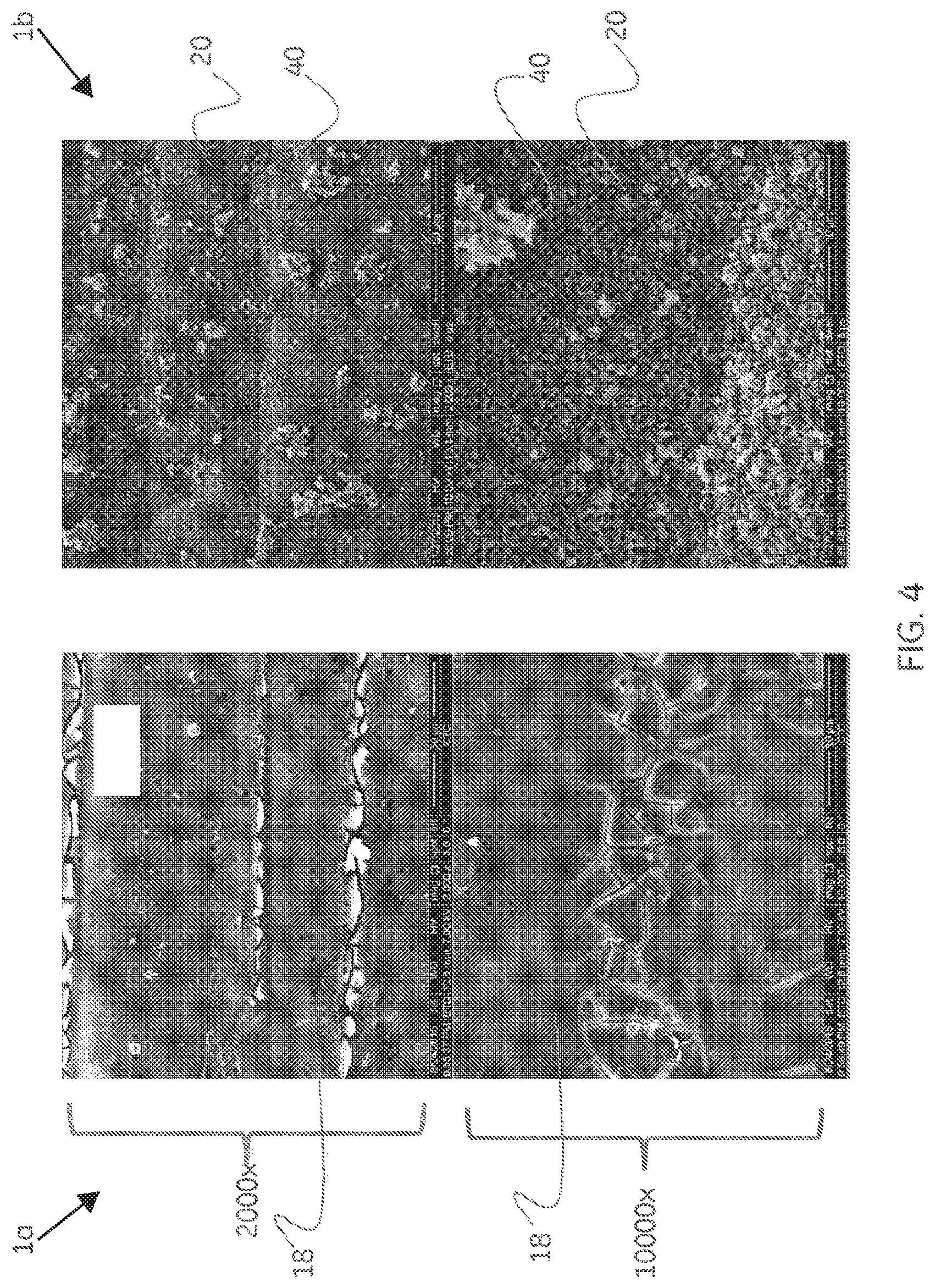
[0012] FIG. 4 is a scanning electron micrograph of a coating prepared according to one or more embodiments of the present invention.
[0013] FIG. 5 is a scanning electron micrograph of a coating prepared according to one or more embodiments of the present invention.
[0014] FIG. 6 is a scanning electron micrograph of a coating prepared according to one or more embodiments of the present invention.
DETAILED DESCRIPTION
[0015] In the following specification and the claims, which follow, reference will be made to a number of terms, which shall be defined to have the following meanings.
[0016] The singular forms "a", "an", and "the" include plural referents unless the context clearly dictates otherwise.
[0017] Approximating language, as used herein throughout the specification and claims, may be applied to modify any quantitative representation that could permissibly vary without resulting in a change in the basic function to which it is related. Accordingly, a value modified by a term or terms, such as "about" and "substantially", are not to be limited to the precise value specified. In at least some instances, the approximating language may correspond to the precision of an instrument for measuring the value. Here and throughout the specification and claims, range limitations may be combined and/or interchanged, such ranges are identified and include all the sub-ranges contained therein unless context or language indicates otherwise.
[0018] As noted, in one or more embodiments the present invention provides a corrosion and scale resistant fluid conduit comprising at least one surface having an electroless nickel (EN) protective coating disposed thereon. A layer of Ni.sub.3S.sub.2, at times herein referred to as Heazlewoodite, is disposed upon and substantially covers the electroless nickel protective coating. The inventors have discovered that nearly all EN protective coatings surprisingly undergo reaction with hydrogen sulfide at moderate temperature and high pressure to form a layer of scale resistant Heazlewoodite on the surface of the EN protective coating initially in contact with a fluid containing hydrogen sulfide. Upon exposure of the EN protective coating to hydrogen sulfide at moderate temperature and high pressure, nickel within the EN protective coating is converted to Ni.sub.3S.sub.2 at or near the surface of the EN coating. The EN coating is thus consumed to some degree during the formation of the Ni.sub.3S.sub.2 layer. As more nickel reacts with hydrogen sulfide to form Ni.sub.3S.sub.2, the EN coating becomes substantially covered with Ni.sub.3S.sub.2 and, as a result, encounters between hydrogen sulfide and nickel atoms present in the EN coating are reduced over time and growth of the Ni.sub.3S.sub.2 layer slows and eventually ceases. Provided the EN coating is of sufficient thickness at the outset of exposure to hydrogen sulfide, the product resulting from such exposure at moderate temperature and pressure will be a layer of Heazlewoodite disposed upon and substantially covering the unconsumed portion of the underlying EN protective layer. Under such circumstances, the unconsumed portion of the underlying EN protective layer is hermetically isolated from contact with the environment provided the structural integrity of the layer of Heazlewoodite is maintained. Example 1b (coupon 1b) in the Experimental Section of this disclosure is illustrative. Of the initial 1 mil (25.4 microns) thick high phosphorous EN protective coating, 25 microns of the original nickel-phosphorous coating remain following reaction with hydrogen sulfide in the presence of brine at 160.degree. C. at a pressure of 2000-3000 psi and deposition of a 10-micron thick Ni.sub.3S.sub.2 overlayer. The Ni.sub.3S.sub.2 overlayer was determined to cover 100% of the outer surface of the unconsumed portion of the underlying EN protective coating and hermetically isolates it from further contact with brine and hydrogen sulfide.
[0019] The Ni.sub.3S.sub.2 overlayer so produced exhibits outstanding scale resistance as is demonstrated experimentally herein. For example, iron sulfide scale FeS (Mackinawite), formed by corrosion of an iron source in the presence of hydrogen sulfide, does not adhere to the Ni.sub.3S.sub.2 overlayer. Moreover, the Ni.sub.3S.sub.2 overlayer is shown to be structurally robust and survives both continuous rotation through brine solution at 300 rpm at 160.degree. C. and high pressure, and explosive decompression test conditions. It is believed that the Ni.sub.3S.sub.2 overlayer will likewise be resistant to other types of scale formation, for example for example the formation of scales comprising calcium carbonate (calcite), barium sulfate, (barite), magnesium carbonate, magnesium sulfate, calcium minerals, iron minerals, silica, dolomite, calcium sulfate, iron carbonate, Fe.sub.2O.sub.3, Fe.sub.3O.sub.4 (magnetite), FeS.sub.2 (iron pyrite), Fe.sub.7S.sub.8 (pyrrhotite), alpha FeOOH, Fe.sub.2(OH).sub.3Cl, beta-FeOOH, and the like.
[0020] In one or more embodiments, the Ni.sub.3S.sub.2 overlayer is characterized by an average thickness in a range from about 0.5 to about 100 microns. In one or more alternate embodiments, the Ni.sub.3S.sub.2 overlayer is characterized by an average thickness in a range from about 1 to about 20 microns. In yet another set of embodiments, the Ni.sub.3S.sub.2 overlayer is characterized by an average thickness in a range from about 1 to about 10 microns.
[0021] The Ni.sub.3S.sub.2 overlayer has been observed by the inventors to form in various morphologies depending on the nature of the initial EN protective coating and/or the conditions under which the Ni.sub.3S.sub.2 overlayer is formed. Thus, the Ni.sub.3S.sub.2 overlayer formed by reaction of a portion of a 1 micron thick high phosphorous electroless nickel coating exhibits a blocky crystalline morphology after prolonged exposure to hydrogen sulfide and brine at moderate temperature and high pressure (See Coupons 1a and 1b, Tables 1 and 2). Contrast this with the rod shaped crystalline morphology of the Ni.sub.3S.sub.2 overlayer observed when an initial 2-micron thick high phosphorous electroless nickel coating is exposed to hydrogen sulfide for a shorter period of time (16 hours) at moderate temperature and pressure (See Coupons 2a and 2b, Tables 1 and 2). The inventors have observed experimentally the formation of Ni.sub.3S.sub.2 overlayers having nanowire morphologies, rod-like morphologies and block-like morphologies; and believe that other Heazlewoodite morphologies such as nanosheet morphologies may be formed as well. In addition, combinations of two or more of such morphologies may be present in a given Ni.sub.3S.sub.2 overlayer. Further, it is believed that higher energy Ni.sub.3S.sub.2 morphologies may be converted to more stable forms upon prolonged heating, for example. Thus, in one or more embodiments, the overlayer of Ni.sub.3S.sub.2 is characterized by one or more morphologies selected from the group consisting of one or more nanosheet morphologies, one or more nanowire morphologies, one or more rod-like morphologies, one or more block-like morphologies, and combinations of two or more of the foregoing morphologies. Ni.sub.3S.sub.2 overlayer morphologies were determined by x-ray diffraction (XRD) and scanning electron microscopy. In one or more embodiments, the Ni.sub.3S.sub.2 layer is initially formed with a nanowire morphology which is transformed under the reaction conditions first to a rod-like morphology and finally to a block-like morphology
[0022] The EN protective coating may contain one or more of a high phosphorous electroless nickel coating, defined as containing from 10 to 20 percent by weight phosphorous based on the total weight of the coating; a mid phosphorous electroless nickel coating, defined as containing from 8 to 9 percent by weight phosphorous based on the total weight of the coating; and a low phosphorous electroless nickel coating, defined as containing less than 8 percent by weight phosphorous based on the total weight of the coating. In one or more embodiments, the EN protective coating is a multilayer coating comprising one or more high phosphorous electroless nickel coatings, one or more mid phosphorous electroless nickel coatings, one or more low phosphorous electroless nickel coatings, or a combination of two or more of the foregoing high, mid and low phosphorous EN coatings. In one or more embodiments, the EN protective coating comprises at least one EN coating devoid of phosphorous (See for example, coupon 3a of Table 1 in which the EN protective coating is a bi-layer comprising an outer electroless nickel boron outer layer essentially free of phosphorous and a high phosphorous electroless nickel inner layer in direct contact with the T95 steel substrate. It should be noted that the heat treatment referred to in Example 3 (coupon 3a), 350.degree. C. for 1 hour, may have resulted in migration of phosphorous into the electroless nickel boron outer layer, and conversely migration of boron into the electroless nickel phosphorous inner layer. Such heat treatment may also result in a metallurgical bond being formed between an EN inner layer and the substrate. Such a metallurgically bound layer is at times herein referred to as a bond layer. Multilayer EN protective coatings may be prepared stepwise, for example by coating the substrate first with a phosphorous-containing EN coating and subsequently subjecting the EN coated substrate to a second electroless nickel coating step. Those of ordinary skill in the art will understand that phosphorous-containing EN protective coatings may be prepared by reduction of dissolved nickel ions with a phosphorous-containing reducing agent such as sodium hypophosphite (NaPO.sub.2H.sub.2) in the presence of a substrate immersed in a medium comprising the dissolved nickel ions and the phosphorous-containing reducing agent. By substituting a boron-containing reducing agent, for example diborane (B.sub.2H.sub.6), for the phosphorous-containing reducing agent an EN protective coating containing boron instead of phosphorous may be obtained.
[0023] In one or more embodiments, the EN protective coating comprises solid particles enhancing one or more performance characteristics of such EN coating. For example, the EN protective coating may contain hard particles (nanoparticulate and larger) such as diamond, silicon carbide, cubic boron nitride, talc silica, alumina, and combinations thereof which enhance abrasion resistance. Alternatively, the EN protective coating may contain soft particles such as polytetrafluoroethylene (PTFE) particles and carbon black particles which enhance resistance to damage caused by movement of a coated surface of a first machine component such as an impeller blade in close proximity to a surface of a second machine component such as a housing. In multi-layer EN protective coatings the particles; hard, soft or a combination thereof, are advantageously present in the outermost EN coating, for example as shown in FIG. 2 of this disclosure. In one or more embodiments, the EN protective coating comprises solid particles in a range from about 10 to about 40 percent by weight based on the total weight of the particular EN coating containing such particles. In an alternate set of embodiments, the EN protective coating comprises solid particles in a range from about 10 to about 25 percent by weight based on the total weight of the particular EN coating containing such particles. In yet another set of embodiments, the EN protective layer comprises solid particles in a range from about 10 to about 15 percent by weight based on the total weight of the particular EN coating containing such particles. It should be noted that the presence in the EN protective coating of soft particulates such as PTFE or hard but heat sensitive particles may limit the maximum temperature at which a particular EN protective coating may be subjected during heat treatment. For example, the structural integrity and/or performance characteristics of EN protective coatings comprising PTFE particles may be compromised if subjected to a heat treatment protocol exceeding about 250.degree. C. owing to decomposition of the PTFE within the EN matrix.
[0024] Fluid conduits provided by the present invention and comprising (a) a fluid conduit exterior surface; (b) a fluid conduit interior surface; (c) an electroless nickel protective coating disposed upon at least one of the fluid conduit interior surface and the fluid conduit exterior surface; and (d) a layer of Ni.sub.3S.sub.2 disposed upon and substantially covering the electroless nickel protective coating, include useful items such as conduits for transporting fluids in the oil and gas industry, for example tubing used in downhole tubular applications in hydrocarbon production wells. In addition to downhole tubing used in hydrocarbon production, conduits provided by the present invention include any sort of structure though which a fluid may be caused to pass, including without limitation, valves, manifolds, blowout preventers, Christmas trees, wellheads, surface pipelines, subsea pipelines, exhaust gas flow lines, cyclonic separators, liquid-liquid separators, and the like. In some embodiments, the fluid conduit is a storage vessel. Storage vessels qualify as fluid conduits in the sense that fluids flow into and out of storage vessels. In another embodiment, the fluid conduit is a continuous reactor.
[0025] In one embodiment, the present invention provides a method of producing a fluid conduit comprising a corrosion and scale resistant nickel sulfide protective layer, the method comprising: (a) heating a fluid conduit comprising an electroless nickel protective coating disposed upon a surface of the fluid conduit in contact with a fluid comprising hydrogen sulfide; and (b) depositing a protective layer of Ni.sub.3S.sub.2 upon and substantially covering the electroless nickel protective coating. Contact between the electroless nickel protective coating and hydrogen sulfide is carried out at moderate temperatures and moderate to high pressures; the temperature being in one or more embodiments, temperatures in a range from about 100.degree. C. to about 400.degree. C., and the pressure being one or more pressures in a range from about 500 to about 3000 psi. In one or more embodiments, contact between the electroless nickel protective coating and hydrogen sulfide is carried out in the presence of an aqueous solution comprising one or more dissolved salts such as sodium chloride, potassium bromide, lithium iodide, calcium chloride, calcium bromide, and combinations of two or more of the foregoing salts. In one or more embodiments, contact between the electroless nickel protective coating and hydrogen sulfide may advantageously be carried out in the presence of one or more protic acids, such as hydrogen chloride, hydrogen bromide, hydrogen iodide, formic acid, and acetic acid. In one or more embodiments, an exogenous protic acid is employed.
[0026] Turning now to the figures, FIG. 1 illustrates a fluid conduit 10 according to one or more embodiments of the present invention. In one or more embodiments, the fluid conduit 10 is a hydrocarbon production tube shown in cross section. Fluid conduit 10 defines an interior volume 12, at times herein referred to as a fluid flow path, through which a fluid may be caused to pass, and comprises a fluid conduit exterior surface 14 and interior surface 16 which together define the thickness the fluid conduit wall bounded by surfaces 14 and 16. An electroless nickel protective coating 18 is disposed on the fluid conduit interior surface 16. In one or more embodiments, a metallurgical bond (not shown) is formed between the electroless nickel protective coating and the fluid conduit interior surface. A layer 20 of Ni.sub.3S.sub.2, also known as Heazlewoodite, is disposed upon and substantially covers the electroless nickel protective coating 18. As used herein, the terms "substantially covers" and "substantially covering" in reference to the Ni.sub.3S.sub.2 layer and adjacent electroless nickel protective coating means that at least 80 percent of the surface area of the electroless nickel protective coating is covered by Ni.sub.3S.sub.2. In one or more embodiments, at least 95 percent of the surface area of the electroless nickel protective coating is covered by Ni.sub.3S.sub.2. In an alternate set of embodiments, at least 99 percent of the surface area of the electroless nickel protective coating is covered by Ni.sub.3S.sub.2.
[0027] Referring to FIG. 2, the figure shows a fluid conduit 10 according to one or more embodiments of the present invention. The figure may represent, for example, a hydrocarbon production tube, a fluid conduit defining a fluid flow path within a compressor, a fluid conduit defining a fluid flow path within a gas-liquid separator, a fluid conduit defining a flow path within a valve, and like fluid conduits. In the embodiment shown, the electroless nickel protective coating is configured as a bilayer coating comprising an inner electroless nickel bond layer 22 comprising from about 10 to about 20% by weight phosphorous based on a total weight of the electroless nickel bond layer, and an electroless nickel outer layer 24 comprising hard particles 26 selected from the group consisting of diamond, silicon carbide, boron nitride, talc, and combinations of two or more of the foregoing hard particle types. A layer 20 of Ni.sub.3S.sub.2 substantially covers and hermetically seals electroless nickel outer layer 24 from fluid contact with the interior volume 12 defined by the fluid conduit.
[0028] Referring to FIG. 3, the figure represents a machine component 30 according to one or more embodiments of the present invention. The figure may represent, for example, an impeller blade, a compressor blade, an expander blade, a baffle, a diffuser within a fluid pump, a valve gate, and like machine components. During operation, machine component 30 may be disposed within a fluid conduit provided by the present invention, for example a fluid conduit defining a fluid flow path within a compressor, a fluid conduit defining a fluid flow path within a gas-liquid separator, a fluid conduit defining a flow path within a valve, and like fluid conduits. In the embodiment shown, a protective outer layer 32 is disposed upon the machine component surface 34. The protective outer layer 32 comprises an inner electroless nickel coating 18, and a layer 20 of Ni.sub.3S.sub.2 disposed upon and substantially covering the electroless nickel coating. In one or more embodiments, the layer of Ni.sub.3S.sub.2 hermetically seals the electroless nickel coating 18 from fluid contact with the environment. In one or more embodiments, the electroless nickel coating 18 hermetically seals the machine component surface 34 from fluid contact with the environment, as in the case wherein at least a portion of the electroless nickel coating 18 remains in fluid contact with the environment following deposition of the layer 20 of Ni.sub.3S.sub.2.
[0029] Referring to FIG. 4, the figure presents scanning electron micrographs showing the typical appearance of electroless nickel phosphorous-coated (ENP-coated) test coupon surface before and after exposure to hydrogen sulfide (See Experimental Part, Example 1a/1b, Tables 1 and 2). In the embodiment shown, are 2000.times. and 10000.times. magnification SEM images of ENP-coated test coupon 1a (Table 1) before exposure to hydrogen sulfide and ENP/Ni.sub.3S.sub.2 test coupon 1b (Table 2) after exposure to hydrogen sulfide at moderate temperature and high pressure. The SEM images of test coupon 1a show the smooth electroless nickel coating 18 covering essentially all of the coupon surface. ENP/Ni.sub.3S.sub.2-coated test coupon 1b shows a deposit of Ni.sub.3S.sub.2 covering essentially all of the ENP coating. Note that lighter colored surface deposits 40 have been identified by XRD and EDS as Mackinawite (FeS) and are shown experimentally herein to represent FeS formed by corrosive scaling of an uncoated T95 steel control coupon and deposition upon the Ni.sub.3S.sub.2 surface coating of test coupon 1b. In FIG. 4 and elsewhere herein, the Heazlewoodite (Ni.sub.3S.sub.2) layer 20 can be clearly seen to be a conformal, micro- or nano-crystalline coating with low affinity for FeS. The Ni.sub.3S.sub.2 layer 20 has been found to adhere tenaciously to the underlying electroless nickel coating 18.
[0030] Referring to FIG. 5, the figure presents scanning electron micrographs showing a second ENP-coated test coupon surface before and after exposure to hydrogen sulfide (See Experimental Part, Example 2a/2b, Tables 1 and 2). In the embodiment shown, 2000.times. and 10000.times. magnification SEM images of ENP-coated test coupon 2a (Table 1) before exposure to hydrogen sulfide and ENP/Ni.sub.3S.sub.2-coated test coupon 2b (Table 2) after exposure to hydrogen sulfide at moderate temperature and high pressure. The SEM images of test coupon 2a show the smooth electroless nickel coating 18 covering essentially all of the coupon surface. ENP/Ni.sub.3S.sub.2-coated test coupon 2b shows a deposit of Ni.sub.3S.sub.2 covering essentially all of the ENP coating. Again, lighter colored surface deposits 40 were identified by XRD and EDS as Mackinawite (FeS) derived from the unprotected control coupon present during exposure to hydrogen sulfide. Again, the Heazlewoodite (Ni.sub.3S.sub.2) layer 20 can be clearly seen to be conformal with the surface of the underlying electroless nickel coating 18. Moreover, layer 20 shows low affinity for FeS. When resubjected to the hydrogen sulfide-brine test protocol detailed in the Experimental Part herein, the Ni.sub.3S.sub.2 grains were shown by SEM to coarsen and grow in size while retaining low affinity for iron sulfide scale 40. Repetition of the hydrogen sulfide-brine test protocol a third and fourth time showed minimal further growth of the Ni.sub.3S.sub.2 grains, while the quantity of visible FeS surface deposits appeared to have decreased. This suggests that, as the Ni.sub.3S.sub.2 consolidates, it becomes more anti-stick with respect to FeS deposition.
[0031] Referring to FIG. 6, the figure presents scanning electron micrographs showing an eletcroless nickel boron coating (ENB coating) disposed upon a high phosphorous electroless nickel bond layer (not visible in the micrograph) before and after exposure to hydrogen sulfide (See Experimental Part, Example 3a/3b, Tables 1 and 2). The overlayer 20 of Ni.sub.3S.sub.2 which formed on the surface of outer ENB coating was particularly anti-stick with respect to FeS scale. This observation is consistent with it being one of the more hydrophobic coatings prepared during the course of this study, as was established by contact angle measurements. While not wishing to be bound by theory, it is thought that the enhanced hydrophobicity of the Ni.sub.3S.sub.2 layer results from the nano-nodular microstructure of the surface, which makes it difficult for FeS deposits to achieve sufficient contact with the surface to adhere. The nano-nodular microstructure of the EN coating 18 observed in test coupon 3a, is reproduced in test coupon 3b following exposure to the hydrogen sulfide-brine test protocol described in the Experimental Part as a result of the fine microstructure of the Ni.sub.3S.sub.2 overlayer 40. It is noteworthy that, as in the case of ENP coatings, nanocrystalline Ni.sub.3S.sub.2 grows on the ENB surface, however, it grows with a finer microstructure than Ni.sub.3S.sub.2 grown on the ENP coatings. The Ni.sub.3S.sub.2 layer appears to be highly conformal to underlying nano-nodular ENB surface, indicating good adhesion between the ENB and Ni.sub.3S.sub.2 layer.
Experimental Part
General Methods
[0032] Test coupons had dimensions of 2.87 inches by 0.87 inches by 0.125 inches and were made of T95 steel. Electroless nickel coatings were applied by a commercial vendor, Surface Technology, Inc. Robbinsville N.J. 08691.
[0033] Representative coated test coupons are illustrated by entries 1a-7a, 11a-12a, 15a and 26a of Table 1. The test coupons were characterized and shown to be uniformly coated.
TABLE-US-00001 TABLE 1 Test Coupon Electroless Nickel Coatings Example/ Electroless Nickel Coating Underlayer Outerlayer Heat Coupon Composition thickness thickness treatment 1a Mono-layer: high phosphorous ENP.sup.(1) -- 1 mil -- 2a Mono-layer: high phosphorous ENP -- 2 mil -- 3a Bi-layer: ENB.sup.(2) over high 1 mil 1 mil 350.degree. C. phosphorous ENP 4a Bi-layer: High phosphorous.sup.(3) ENP + 1 mil 0.5 mil 250.degree. C. 20-25% PTFE over high phosphorous ENP 5a Bi-Layer: High phosphorous ENP + 1 mil 1 mil -- 20-25% PTFE over high phosphorous ENP 6a Bi-Layer: Low phosphorous.sup.(4) ENP + 1 mil 1 mil -- 10% cubic boron nitride over high phosphorous ENP 7a Bi-Layer: Low phosphorous ENP + 1 mil 1 mil 350.degree. C. 10% cubic boron nitride over high phosphorous ENP 11a Bi-Layer: Mid phosphorous.sup.(5) ENP + 1 mil 4 mil 350.degree. C. 10% Nano-Plate .TM..sup.(6) over high phosphorous ENP 12a Bi-Layer: Low phosphorous ENP + 1 mil 1 mil 350.degree. C. 35% CDC-2-HD.sup.(7) over low phosphorous ENP.sup.5 15a Bi-Layer: Mid phosphorous ENP + 1 mil 4 mil 350.degree. C. 20% SiC.sup.(8) over high phosphorous ENP 26a Mono-Layer: Low phosphorous ENP + -- 4 mil 350.degree. C. 35% CDC-2-HD Key: .sup.(1)Electroless nickel phosphorous. .sup.(2)Electroless nickel boron. .sup.(3)High phosphorous ENP contains 10 to 20% by weight P. .sup.(4)Low phosphorous ENP contains less than 8% by weight P .sup.(5)Mid phosphorous ENP contains 8 to 9% by weight P. .sup.(6)Sub-micron nanoparticulate diamond available from Surface Technology, Inc. .sup.(7)Micron scale diamond particles present in Composite Diamond Coating .TM. available from Surface Technology, Inc. .sup.(8)Silicon carbide.
[0034] In model scaling experiments test coupons were mounted on a rotating cage apparatus and rotated at 300 rpm while in contact with a brine solution within a heated autoclave pressurized with hydrogen sulfide and nitrogen gas. An uncoated T95 steel test coupon was placed in close proximity to the electroless nickel-coated test coupons in order to model corrosive scale formation conditions in which the uncoated T-95 steel test coupon serves as the iron source for FeS scale. Test coupons were weighed before and after being subjected to hours-long exposure to hydrogen sulfide and brine. All electroless nickel-coated test coupons (2a-7a, 11a, 12a and 26a) were observed to increase in weight or remain unchanged in weight (test coupons 1a and 15a) following the model scaling experiments, and all uncoated T95 steel control coupons were observed to decrease in weight following the model scaling experiments. Further, the surface appearance of the electroless nickel-coated test coupons was transformed from a lustrous reflective surface appearance characteristic of electroless nickel coatings, to a dull gray-green surface appearance. The uncoated T-95 steel test coupons turned black under the test conditions.
Preparation of Heazlewoodite (Ni.sub.3S.sub.2) Coatings on Electroless Nickel-Coated Substrate
[0035] Heazlewoodite (Ni.sub.3S.sub.2) coatings were unexpectedly formed on electroless nickel coated substrates during corrosive scaling tests. The tests were carried out in a one-liter C276 steel autoclave equipped with a purge tube and rotating cage apparatus on which were secured five electroless nickel-coated test coupons (See Table 1) and an uncoated control coupon made of T95 steel. A 1 molar sodium chloride solution (500 mL), an amount sufficient to completely submerge all six coupons, was purged continuously in a premixing unit with oxygen free nitrogen gas (99.9999%) over several hours at ambient temperature. The oxygen level in the brine solution was monitored with CHEMetrics ULR CHEMets kit capable of determining the concentration of dissolved oxygen in the brine in a range from about 0 to about 20 parts per billion (ppb). In representative experiments the brine was considered strictly anoxic when the concentration of dissolved oxygen was less than 4 ppb. Once the brine was judged to be strictly anoxic it was transferred to the autoclave under a nitrogen atmosphere. A mixture of hydrogen sulfide and nitrogen gas at atmospheric pressure and ambient temperature (4% H.sub.2S in N.sub.2) (2.0 liters, approximately 100 milligrams of H.sub.2S) was introduced into the autoclave bringing the initial pressure in the autoclave to 55 psi. The pressure inside the autoclave was boosted to 1450-1500 psi using a high pressure pump to introduce additional nitrogen gas. The autoclave was then heated at 160.degree. C. at a pressure of 2250-2370 psi for approximately 16 hours while rotating the rotating cage at 300 rpm. The autoclave was allowed to cool to ambient temperature and was vented through a H.sub.2S scrubber and purged with nitrogen. The test coupons were rinsed with deionized water, dried and characterized variously by weight gain, explosive decompression testing, X-ray powder diffraction (XRD) and electron microscopy. Representative Ni.sub.3S.sub.2 coated test coupons are illustrated by entries 1b-7b, 11b-12b, 15b and 26b of Table 2.
TABLE-US-00002 TABLE 2 Electroless Nickel Coatings with Ni.sub.3S.sub.2 Outer Layer Ni.sub.3S.sub.2 Example/ layer Ni.sub.3S.sub.2 layer Ni.sub.3S.sub.2 % Scale % Mass Coupon thickness morphology Coverage Resistance Gain 1b 0.5-1.0 Blocky 100% good 0.0 microns crystals 2b.sup.(1) 1-2 Rod shaped 100% good 0.0147 micron.sup.(2) crystals 3b NA.sup.(3) NA.sup.(3) 100% good 0.018 4b NA.sup.(3) NA.sup.(3) NA.sup.(3) Very good 0.0927 5b NA.sup.(3) NA.sup.(3) NA.sup.(3) Very good 0.051 6b NA.sup.(3) NA.sup.(3) NA.sup.(3) Very good 0.0613 7b NA.sup.(3) NA.sup.(3) NA.sup.(3) good 0.156 11b NA.sup.(3) NA.sup.(3) NA.sup.(3) Very good 0.0601 12b.sup.(4) 10 micron Blocky, with 100% Very good 0.0563 some embedded diamond 15b.sup.(5) 10 micron Continuous, 100% Very Good blocky, mixed with SiC crystals 26b.sup.(6) 10 micron Continuous 50% Very good 0.0395 with exposed diamond particle surfaces Key: .sup.(1)Single 16 hour cycle as described above but with higher initial H.sub.2S pressure (100 psi versus 55 psi). .sup.(2)Ni.sub.3S.sub.2 layer passed explosive decompression test. .sup.(3)Not Ascertained .sup.(4)Two 16 hour cycles with initial H.sub.2S pressure of 55 psi. .sup.(5)Prolonged exposure to hydrogen sulfide-brine protocol. .sup.(6)Single 16 hour cycle as described above but with higher initial H.sub.2S pressure (100 psi versus 55 psi), higher brine concentration (3 molar) and the addition of a source of soluble Fe.sup.2+ ions.
[0036] The electroless nickel-Ni.sub.3S.sub.2 coated coupons were observed to have excellent resistance to scale adhesion on the outer Ni.sub.3S.sub.2 layer which in nearly all instances covered essentially 100% of the outer surface test coupon. In one instance, test coupon 26a was observed to provide a Ni.sub.3S.sub.2 coating covering only about 50% of the surface of the test coupon. This was thought to be due to the relatively high concentration of diamond particles in the original electroless nickel mono-layer. Notwithstanding the partial covering observed for test coupon 26b, the Ni.sub.3S.sub.2 outer layer exhibited very good resistance to scale accretion. The exposed diamond particle surfaces at the outer surface of the Ni.sub.3S.sub.2 layer were apparently non-stick with respect to FeS scale as well.
[0037] The experimental results indicate that the thickness of the Heazlewoodite layer may be limited to about 10 microns. Thus, coupon 1b having an initial layer of Ni.sub.3S.sub.2 having a thickness between about 0.5 and 1.0 microns thick, was subjected to extended exposure to hydrogen sulfide and brine over a twenty-one day period during which the Ni.sub.3S.sub.2 layer grew in thickness to about 10 microns. Of the initial 1 mil (25.4 microns) thick high phosphorous ENP layer, 25 microns of a nickel-phosphorous layer remained following deposition of the Ni.sub.3S.sub.2 overlayer. Coupons 12b, 15b, and 26b comprised Ni.sub.3S.sub.2 layers about 10 microns thick. Thus it appears that longer reaction times and/or higher concentrations of hydrogen sulfide did not result in Ni.sub.3S.sub.2 coatings having thicknesses greater than 10 microns.
Method 1: Preparation of Heazlewoodite (Ni.sub.3S.sub.2) Coating on an Electroless Nickel-Coated Hydrocarbon Production Tube
[0038] A hydrocarbon production tube approximately 30 feet in length, threaded at both ends, having an outer diameter of approximately 4.5 inches and having inner and outer surfaces is first coated with the electroless nickel coating composition of Example 1a of Table 1 of this disclosure on the inner surface of the tube to a thickness of approximately 2 mil. As noted, such electroless nickel coatings may be applied by commercial applicators such as Surface Technology, Inc. of Robbinsville, N.J. A first end of the tube is sealed with a first threaded steel cap likewise coated with 2 mil of the high phosphorous ENP coating of Example 1a. The tube is then moved into a vertical position open end up. Sufficient 1 molar sodium chloride brine solution to fill approximately three quarters of the length of the tube is added to the tube through the open end. The open end of the tube is then sealed with a second threaded steel cap, likewise coated with 2 mil of the high phosphorous ENP coating of Example 1a. The second threaded steel cap is equipped with gas inlet and gas outlet ports. The headspace within the tube is purged with nitrogen at atmospheric pressure and then pressurized with 4% hydrogen sulfide in nitrogen gas mixture to 1400 psi. The tube is then inserted horizontally into an oven equipped with roller bearings which allow the tube to be rotated at approximately 60 rpm. The oven is sized such that the entire length of the tube may be heated during a single heating cycle without moving the tube horizontally through the oven at any point during the heating cycle. The oven temperature is raised to approximately 160.degree. C. and heated at that temperature for 24 hours while rotating the tube at 60 rpm. The tube is allowed to cool and is vented through a hydrogen sulfide scrubber while purging with nitrogen gas. The brine solution is recovered for reuse and the tube is rinsed inside and out with fresh water and allowed to dry. The product hydrocarbon production tube comprises an electroless nickel protective coating disposed upon the interior surface of the tube and a layer of Ni.sub.3S.sub.2 disposed upon and substantially covering the electroless nickel protective coating.
Method 2: Preparation of Heazlewoodite (Ni.sub.3S.sub.2) Coating on an Electroless Nickel-Coated Hydrocarbon Production Tube Under Strictly Anoxic Conditions
[0039] The method is essentially the same as Method 1 herein with the exception that the brine solution is thoroughly deoxygenated prior to addition of the brine to the tube, and such addition is carried out under a strictly anoxic atmosphere. A source of ferrous ions (ferrous chloride) is added, again under strictly anoxic conditions. The open end of the tube is then sealed with a second threaded steel cap, likewise coated with 2 mil of the high phosphorous ENP coating of Example 1a. The second threaded steel cap is equipped with gas inlet and gas outlet ports. The headspace within the tube is purged with nitrogen at atmospheric pressure and then pressurized with 4% hydrogen sulfide in nitrogen gas mixture to 1400 psi. The tube is then inserted horizontally into an oven equipped with roller bearings which allow the tube to be rotated at approximately 60 rpm. The oven is sized such that the entire length of the tube may be heated during a single heating cycle without moving the tube horizontally through the oven at any point during the heating cycle. The oven temperature is raised to approximately 160.degree. C. and heated at that temperature for 24 hours while rotating the tube at 60 rpm. The tube is allowed to cool and is vented through a hydrogen sulfide scrubber while purging with nitrogen gas. The brine solution is recovered for reuse and the tube is rinsed inside and out with fresh water and allowed to dry. The product hydrocarbon production tube comprises an electroless nickel protective coating disposed upon the interior surface of the tube and a layer of Ni.sub.3S.sub.2 disposed upon and substantially covering the electroless nickel protective coating.
[0040] The foregoing examples are merely illustrative, serving to illustrate only some of the features of the invention. The appended claims are intended to claim the invention as broadly as it has been conceived and the examples herein presented are illustrative of selected embodiments from a manifold of all possible embodiments. Accordingly, it is Applicants' intention that the appended claims are not to be limited by the choice of examples utilized to illustrate features of the present invention. As used in the claims, the word "comprises" and its grammatical variants logically also subtend and include phrases of varying and differing extent such as for example, but not limited thereto, "consisting essentially of" and "consisting of" Where necessary, ranges have been supplied, those ranges are inclusive of all sub-ranges there between. It is to be expected that variations in these ranges will suggest themselves to a practitioner having ordinary skill in the art and where not already dedicated to the public, those variations should where possible be construed to be covered by the appended claims. It is also anticipated that advances in science and technology will make equivalents and substitutions possible that are not now contemplated by reason of the imprecision of language and these variations should also be construed where possible to be covered by the appended claims.
* * * * *
D00000
D00001
D00002
D00003
D00004
D00005
D00006
XML
uspto.report is an independent third-party trademark research tool that is not affiliated, endorsed, or sponsored by the United States Patent and Trademark Office (USPTO) or any other governmental organization. The information provided by uspto.report is based on publicly available data at the time of writing and is intended for informational purposes only.
While we strive to provide accurate and up-to-date information, we do not guarantee the accuracy, completeness, reliability, or suitability of the information displayed on this site. The use of this site is at your own risk. Any reliance you place on such information is therefore strictly at your own risk.
All official trademark data, including owner information, should be verified by visiting the official USPTO website at www.uspto.gov. This site is not intended to replace professional legal advice and should not be used as a substitute for consulting with a legal professional who is knowledgeable about trademark law.