Reinforced Collapsible Box
Sollie; Greg ; et al.
U.S. patent application number 16/554699 was filed with the patent office on 2019-12-19 for reinforced collapsible box. The applicant listed for this patent is Pratt Corrugated Holdings, Inc.. Invention is credited to Greg Sollie, Jamie Waltermire.
| Application Number | 20190382154 16/554699 |
| Document ID | / |
| Family ID | 65630484 |
| Filed Date | 2019-12-19 |


View All Diagrams
| United States Patent Application | 20190382154 |
| Kind Code | A1 |
| Sollie; Greg ; et al. | December 19, 2019 |
REINFORCED COLLAPSIBLE BOX
Abstract
A reinforced box includes a body board including a first material, the body board including a bottom panel defining a first bottom side and a second bottom side, the first bottom side positioned opposite from the second bottom side; a first side panel hingedly attached to the first bottom side of the bottom panel; and a second side panel hingedly attached to the second bottom side of the bottom panel; and an end panel including a second material, the second material being different from the first material, the end panel attached to the first side panel and the second side panel.
| Inventors: | Sollie; Greg; (Sharpsburg, GA) ; Waltermire; Jamie; (Peachtree City, GA) | ||||||||||
| Applicant: |
|
||||||||||
|---|---|---|---|---|---|---|---|---|---|---|---|
| Family ID: | 65630484 | ||||||||||
| Appl. No.: | 16/554699 | ||||||||||
| Filed: | August 29, 2019 |
Related U.S. Patent Documents
| Application Number | Filing Date | Patent Number | ||
|---|---|---|---|---|
| 15699534 | Sep 8, 2017 | 10435194 | ||
| 16554699 | ||||
| Current U.S. Class: | 1/1 |
| Current CPC Class: | B65D 5/3628 20130101; B65D 5/42 20130101; B65D 5/4266 20130101; B65D 5/36 20130101; B65D 5/66 20130101; B65D 5/6605 20130101 |
| International Class: | B65D 5/36 20060101 B65D005/36; B65D 5/66 20060101 B65D005/66; B65D 5/42 20060101 B65D005/42 |
Claims
1. A reinforced box comprising: a body board comprising a first material, the body board comprising: a bottom panel defining a first bottom side and a second bottom side, the first bottom side positioned opposite from the second bottom side; a first side panel hingedly attached to the first bottom side of the bottom panel; and a second side panel hingedly attached to the second bottom side of the bottom panel; and an end panel comprising a second material, the second material being different from the first material, the end panel attached to the first side panel and the second side panel.
2. The reinforced box of claim 1, wherein: the first material defines a first thickness; the second material defines a second thickness; and the second thickness is larger than the first thickness.
3. The reinforced box of claim 1, wherein: the first material is lightweight cardboard; and the second material is heavyweight cardboard.
4. The reinforced box of claim 1, wherein: the end panel is a first end panel; the reinforced box comprises a second end panel positioned opposite from the first end panel; the second end panel comprises the second material; and the second end panel is attached to the first side panel and the second side panel.
5. The reinforced box of claim 1, wherein: the first side panel comprises a side flap; and the side flap is attached to the end panel.
6. The reinforced box of claim 5, wherein the side flap is attached to the end panel with an adhesive.
7. The reinforced box of claim 1, wherein: the body board further comprises an end flap hingedly attached to an end of the bottom panel; the end extends between the first bottom side and the second bottom side; and the end flap is attached to the end panel.
8. The reinforced box of claim 7, wherein: the end flap is a first end flap; the body board further comprises a second end flap hingedly attached to the end of the bottom panel; the second end flap is attached to the end panel; an end flap notch is defined between the first end flap and the second end flap; and the end flap notch is configured to provide clearance for the bottom panel to collapse.
9. A method of assembling a reinforced box, the method comprising: folding a first side panel about a first side hinge relative to a bottom panel; folding a second side panel about a second side hinge relative to the bottom panel, the first side panel, the second side panel, and the bottom panel comprised by a body board of the reinforced box, the body board comprising a first material; attaching a first end panel to the first side panel and the second side panel, the first end panel comprising a second material, the second material being different from the first material; and attaching a second end panel to the first side panel and the second side panel, the second end panel comprising the second material.
10. The method of claim 9, wherein: the first material defines a first thickness; the second material defines a second thickness; and the second thickness is larger than the first thickness.
11. The method of claim 9, wherein: the first side panel comprises a first side flap and a second side flap; attaching the first end panel to the first side panel comprises attaching the first side flap to the first end panel; and attaching the second end panel to the first side panel comprises attaching the second side flap to the first end panel.
12. The method of claim 11, wherein attaching the first side flap to the first end panel comprises adhering the first side flap to the first end panel.
13. The method of claim 11, wherein the first side flap and the second side flap are hingedly connected to the first side panel.
14. The method of claim 9, further comprising attaching an end flap of the body board to the first end panel, the end flap hingedly attached to the bottom panel.
15. The method of claim 14, wherein the end flap is a first end flap, and wherein the method further comprises attaching a second end flap of the body board to the first end panel, the second end flap hingedly attached to the bottom panel.
16. The method of claim 14, wherein an end flap notch is defined between the first end flap and the second end flap; and wherein the end flap notch provides clearance for the bottom panel to collapse.
17. The method of claim 9, wherein: the body board further comprises a first top flap hingedly attached to the first side panel by a first top flap hinge and a second top flap hingedly attached to the second side panel by a second top flap hinge; and the method further comprises: folding the first top flap about the first top flap hinge; folding the second top flap about the second top flap hinge; and engaging the first top flap with the second top flap.
18. The method of claim 17, wherein engaging the first top flap with the second top flap comprises interlocking a first top notch with a second top notch, the first top notch defined by a first top flap end of the first top flap, the second top notch defined by a second top flap end of the second top flap.
Description
REFERENCE TO RELATED APPLICATIONS
[0001] This application is a continuation of U.S. application Ser. No. 15/699,534, filed Sep. 8, 2017, which is hereby specifically incorporated by reference herein in its entirety.
TECHNICAL FIELD
[0002] This disclosure relates to packaging. More specifically, this disclosure relates to a reinforced box.
BACKGROUND
[0003] Many boxes are often formed from a single sheet of material, such as a box blank. The box blank can often be a rigid board material, such as corrugated cardboard. The structural strength can depend upon the strength of the material used. For example, using a stronger material for the box can increase a stacking strength of the box which is the amount of downward force that can be exerted on the box before the box fails. However, not all portions of the box contribute equally to the stacking strength of the box, and some panels may not require heavier material to maintain the stacking strength of the box. For example, a bottom panel of the box has little effect on the stacking strength of the box; however, side panels of the box demonstrate a large effect on the stacking strength of the box. Because many box designs are formed from a single sheet of material, the bottom panel is often also comprised of heavier material than necessary to provide the desired stacking strength of the box leading to increased material costs.
SUMMARY
[0004] It is to be understood that this summary is not an extensive overview of the disclosure. This summary is exemplary and not restrictive, and it is intended to neither identify key or critical elements of the disclosure nor delineate the scope thereof. The sole purpose of this summary is to explain and exemplify certain concepts of the disclosure as an introduction to the following complete and extensive detailed description.
[0005] Disclosed is a reinforced box comprising a body board comprising a first material, the body board comprising a bottom panel defining a first bottom side and a second bottom side, the first bottom side positioned opposite from the second bottom side; a first side panel hingedly attached to the first bottom side of the bottom panel; and a second side panel hingedly attached to the second bottom side of the bottom panel; and an end panel comprising a second material, the second material being different from the first material, the end panel attached to the first side panel and the second side panel.
[0006] Also disclosed is a method of assembling a reinforced box, the method comprising folding a first side panel about a first side hinge relative to a bottom panel; folding a second side panel about a second side hinge relative to the bottom panel, the first side panel, the second side panel, and the bottom panel comprised by a body board of the reinforced box, the body board comprising a first material; attaching a first end panel to the first side panel and the second side panel, the first end panel comprising a second material, the second material being different from the first material; and attaching a second end panel to the first side panel and the second side panel, the second end panel comprising the second material.
[0007] Various implementations described in the present disclosure may include additional systems, methods, features, and advantages, which may not necessarily be expressly disclosed herein but will be apparent to one of ordinary skill in the art upon examination of the following detailed description and accompanying drawings. It is intended that all such systems, methods, features, and advantages be included within the present disclosure and protected by the accompanying claims. The features and advantages of such implementations may be realized and obtained by means of the systems, methods, features particularly pointed out in the appended claims. These and other features will become more fully apparent from the following description and appended claims, or may be learned by the practice of such exemplary implementations as set forth hereinafter.
BRIEF DESCRIPTION OF THE DRAWINGS
[0008] The features and components of the following figures are illustrated to emphasize the general principles of the present disclosure. The drawings are not necessarily drawn to scale. Corresponding features and components throughout the figures may be designated by matching reference characters for the sake of consistency and clarity.
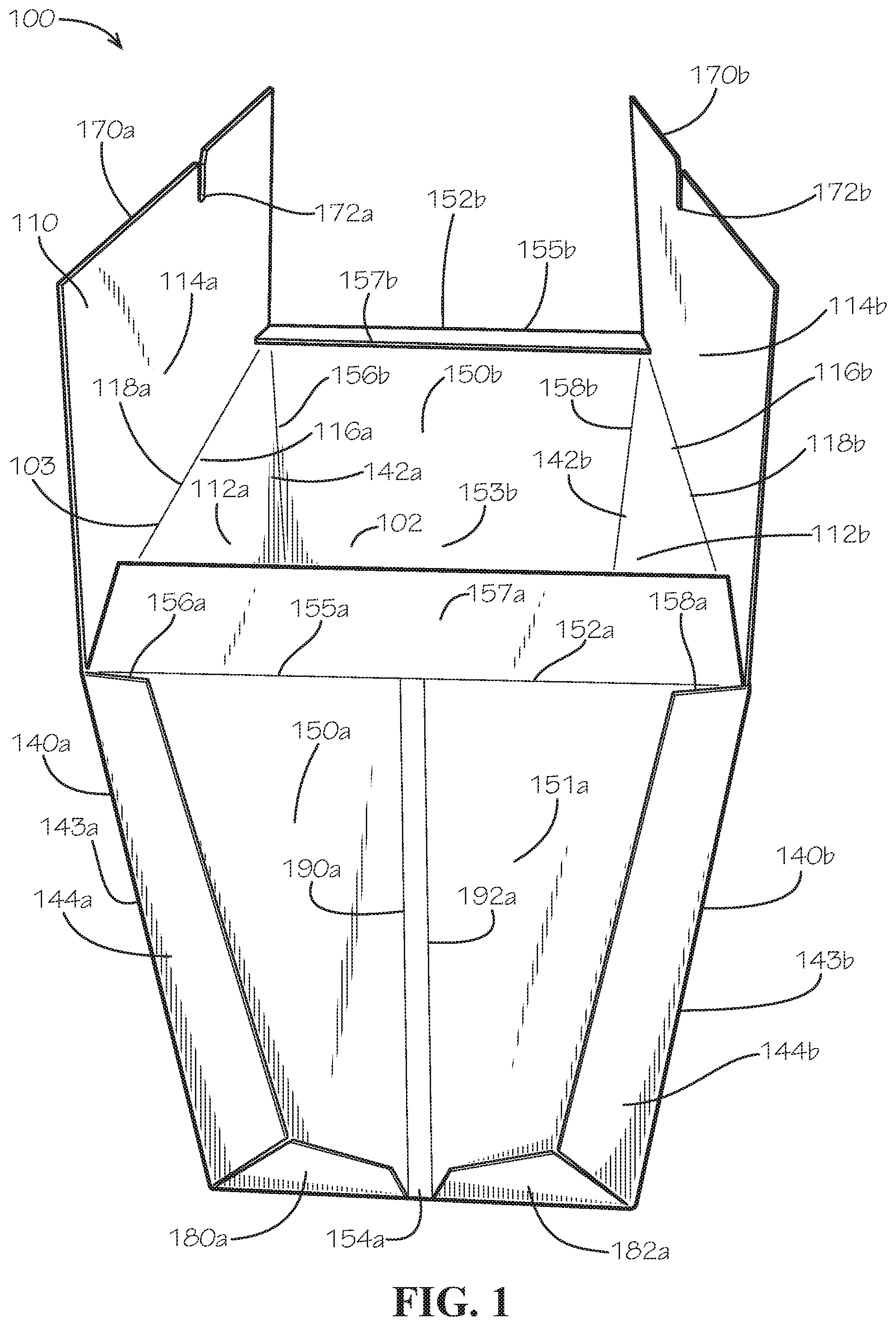
[0009] FIG. 1 is a top perspective view of a reinforced box in an open configuration in accordance with one aspect of the present disclosure.
[0010] FIG. 2 is a perspective side view of the reinforced box of FIG. 1 facing a second end panel of the reinforced box.
[0011] FIG. 3 is a bottom perspective view of the reinforced box of FIG. 1 facing a first end panel and a bottom panel of the reinforced box.
[0012] FIG. 4 is a perspective side view facing the first end panel of the reinforced box of FIG. 1 in a partially collapsed configuration.
[0013] FIG. 5 is a perspective view of the reinforced box of FIG. 1 in a collapsed configuration.
[0014] FIG. 6 is a top view of a body board of the reinforced box of FIG. 1.
[0015] FIG. 7 is a top view of the first end panel of the reinforced box of FIG. 1.
[0016] FIG. 8 is a top view of the reinforced box of FIG. 1 in a disassembled state.
[0017] FIG. 9 is a perspective view of the reinforced box of FIG. 1 in a partially assembled state.
[0018] FIG. 10 is a top detail view of the reinforced box of FIG. 1 in a closed configuration showing a first top notch of the reinforced box interlocking with a second top notch of the reinforced box.
[0019] FIG. 11 is a detailed perspective view of a first sealing tab of a first top flap of the reinforced box of FIG. 1.
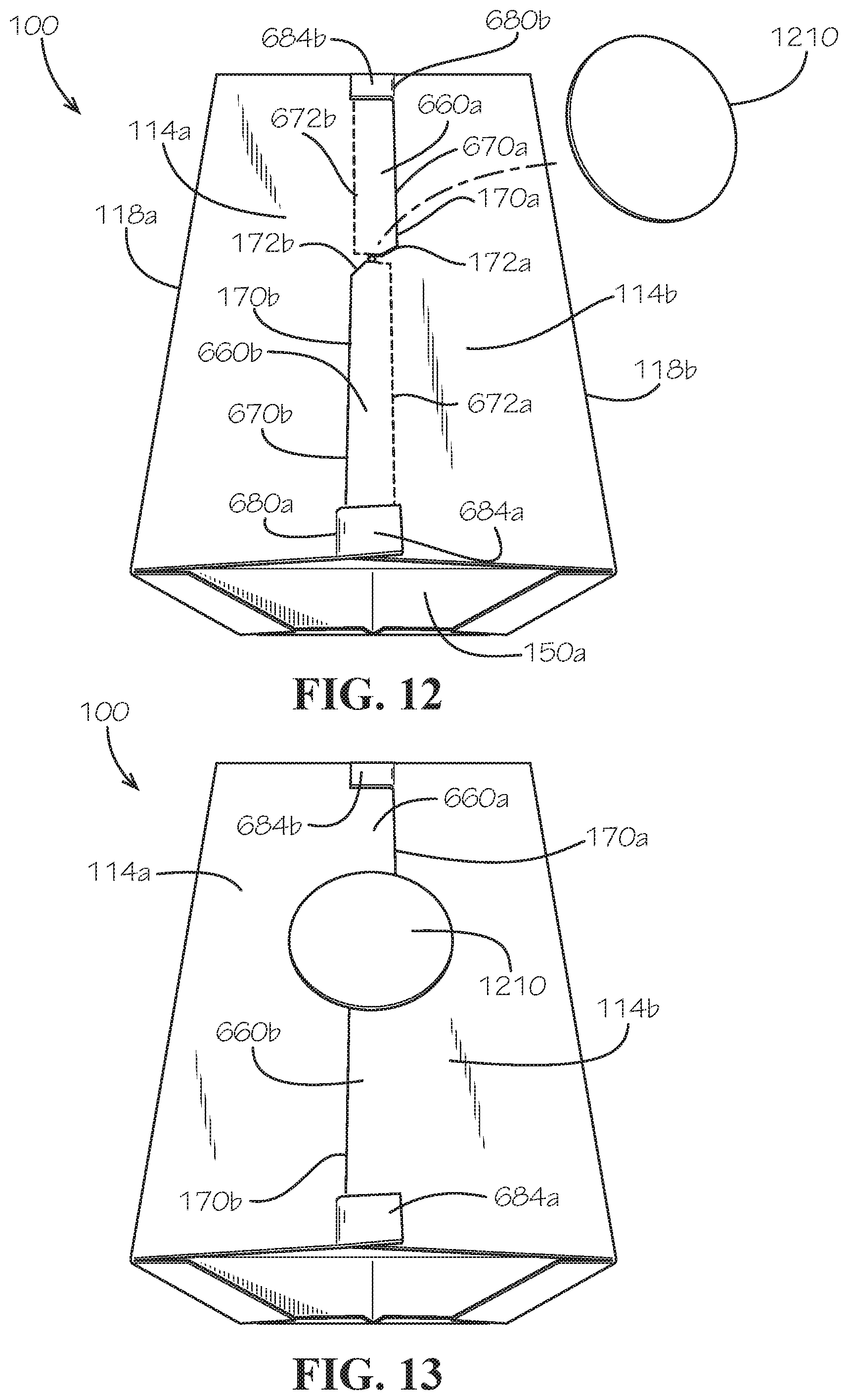
[0020] FIG. 12 is a perspective top view of the reinforced box of FIG. 1 in the closed configuration and further comprising an adhesive seal.
[0021] FIG. 13 is a perspective top view of the reinforced box of FIG. 1 in the closed configuration with the adhesive seal attached to the reinforced box.
DETAILED DESCRIPTION
[0022] The present disclosure can be understood more readily by reference to the following detailed description, examples, drawings, and claims, and the previous and following description. However, before the present devices, systems, and/or methods are disclosed and described, it is to be understood that this disclosure is not limited to the specific devices, systems, and/or methods disclosed unless otherwise specified, and, as such, can, of course, vary. It is also to be understood that the terminology used herein is for the purpose of describing particular aspects only and is not intended to be limiting.
[0023] The following description is provided as an enabling teaching of the present devices, systems, and/or methods in its best, currently known aspect. To this end, those skilled in the relevant art will recognize and appreciate that many changes can be made to the various aspects of the present devices, systems, and/or methods described herein, while still obtaining the beneficial results of the present disclosure. It will also be apparent that some of the desired benefits of the present disclosure can be obtained by selecting some of the features of the present disclosure without utilizing other features. Accordingly, those who work in the art will recognize that many modifications and adaptations to the present disclosure are possible and can even be desirable in certain circumstances and are a part of the present disclosure. Thus, the following description is provided as illustrative of the principles of the present disclosure and not in limitation thereof.
[0024] As used throughout, the singular forms "a," "an" and "the" include plural referents unless the context clearly dictates otherwise. Thus, for example, reference to "an element" can include two or more such elements unless the context indicates otherwise.
[0025] Ranges can be expressed herein as from "about" one particular value, and/or to "about" another particular value. When such a range is expressed, another aspect includes from the one particular value and/or to the other particular value. Similarly, when values are expressed as approximations, by use of the antecedent "about," it will be understood that the particular value forms another aspect. It will be further understood that the endpoints of each of the ranges are significant both in relation to the other endpoint, and independently of the other endpoint.
[0026] For purposes of the current disclosure, a material property or dimension measuring about X or substantially X on a particular measurement scale measures within a range between X plus an industry-standard upper tolerance for the specified measurement and X minus an industry-standard lower tolerance for the specified measurement. Because tolerances can vary between different materials, processes and between different models, the tolerance for a particular measurement of a particular component can fall within a range of tolerances.
[0027] As used herein, the terms "optional" or "optionally" mean that the subsequently described event or circumstance can or cannot occur, and that the description includes instances where said event or circumstance occurs and instances where it does not.
[0028] The word "or" as used herein means any one member of a particular list and also includes any combination of members of that list. Further, one should note that conditional language, such as, among others, "can," "could," "might," or "may," unless specifically stated otherwise, or otherwise understood within the context as used, is generally intended to convey that certain aspects include, while other aspects do not include, certain features, elements and/or steps. Thus, such conditional language is not generally intended to imply that features, elements and/or steps are in any way required for one or more particular aspects or that one or more particular aspects necessarily include logic for deciding, with or without user input or prompting, whether these features, elements and/or steps are included or are to be performed in any particular aspect.
[0029] Disclosed are components that can be used to perform the disclosed methods and systems. These and other components are disclosed herein, and it is understood that when combinations, subsets, interactions, groups, etc. of these components are disclosed that while specific reference of each various individual and collective combinations and permutation of these may not be explicitly disclosed, each is specifically contemplated and described herein, for all methods and systems. This applies to all aspects of this application including, but not limited to, steps in disclosed methods. Thus, if there are a variety of additional steps that can be performed it is understood that each of these additional steps can be performed with any specific aspect or combination of aspects of the disclosed methods.
[0030] Disclosed is a reinforced box and associated methods, systems, devices, and various apparatus. The reinforced box comprises a body board, a first end panel, and a second end panel. It would be understood by one of skill in the art that the disclosed reinforced box is described in but a few exemplary embodiments among many. No particular terminology or description should be considered limiting on the disclosure or the scope of any claims issuing therefrom.
[0031] FIG. 1 is a top perspective view of a reinforced box 100 in an open configuration in accordance with one aspect of the present disclosure. The reinforced box 100 can comprise a body board 110, a first end panel 150a, and a second end panel 150b. The first end panel 150a and the second end panel 150b can be arranged opposite from one another as a pair of opposing end panels 150a,b. The body board 110 can comprise a first side panel 112a and a second side panel 112b. The first side panel 112a and the second side panel 112b can be arranged opposite from one another as a pair of opposing side panels 112a,b. A box cavity 102 can be defined within the reinforced box 100 by the side panels 112a,b and the end panels 150a,b.
[0032] Each of the side panels 112a,b can define a first side 140a,b and a second side 142a,b, respectively, and the first sides 140a,b can be disposed opposite from the second sides 142a,b. The first sides 140a,b can be positioned by the first end panel 150a, and the second sides 142a,b can be positioned by the second end panel 150b. Each of the side panels 112a,b can define a top end 116a,b, respectively, extending between the sides 140a,b,142a,b.
[0033] Each of the end panels 150a,b can define a top end 152a,b, respectively, and in the present aspect, the top ends 152a,b of the end panels 150a,b can be substantially flush with the top ends 116a,b of the respective side panels 112a,b. The top ends 116a,b,152a,b can define a box opening 103 of the box cavity 102. The box opening 103 can be uncovered and the box cavity 102 can be exposed in the open configuration. Each of the end panels 150a,b can define a bottom end 154a,b (bottom end 154b shown in FIG. 2). Each of the end panels 150a,b can define a first side 156a,b positioned adjacent to the first side panel 112a and a second side 158a,b positioned adjacent to the second side panel 112b. Each end panel 150a,b can respectively define an outer surface 151a,b (outer surface 151b shown in FIG. 2) and an inner surface 153a,b (inner surface 153a shown in FIG. 8). The inner surfaces 153a,b can face inwards towards the box cavity 102, and the outer surfaces 151a,b can face outwards and away from the box cavity 102.
[0034] A first side flap 144a,b of the respective side panel 112a,b can each be hingedly attached to the respective first side 140a,b by a first side flap hinge 143a,b, respectively. The first side flaps 144a,b can be folded at the first side flap hinges 143a,b to cover portions of the outer surface 151a proximate to the respective sides 156a,158a of the first end panel 150a. The first side flaps 144a,b can be attached to the outer surface 151a of the first end panel 150a to secure the first end panel 150a to the side panels 112a,b. In the present aspect, the first side flaps 144a,b can be bonded to the first end panel 150a with an adhesive; however in other aspects, the first side flaps 144a,b can be attached to the first end panel 150a through another method, such as stapling, stitching, or any other suitable method.
[0035] Additionally, a first end flap 180a and a second end flap 182a can be folded over and attached to the outer surface 151a of the first end panel 150a at the bottom end 154a to further secure the first end panel 150a to the body board 110. In the present aspect, the end flaps 180a,182a can be bonded to the first end panel 150a with an adhesive; however in other aspects, the end flaps 180a,182a can be attached to the first end panel 150a through another method, such as stapling, stitching, or any other suitable method.
[0036] In the present aspect, the first end panel 150a can define a first end fold line 190a and a second end fold line 192a which can extend from the top end 152a to the bottom end 154a of the first end panel 150a. The first end fold line 190a can be spaced apart from and substantially parallel to the second end fold line 192a so that a portion of the first end panel 140a extends between the first end fold line 190a and the second end fold line 192a. The first end flap 180a can be positioned between the first side panel 112a and the first end fold line 190a, and the second end flap 182a can be positioned between the second side panel 112b and the second end fold line 192a.
[0037] A first top flap 114a can be hingedly attached to the top end 116a of the first side panel 112a by a first top flap hinge 118a. A second top flap 114b can be hingedly attached to the top end 116b of the second side panel 112b by a second top flap hinge 118b. Each top flap 114a,b can define a top flap end 170a,b, respectively, which can be disposed opposite from the respective top flap hinge 118a,b. Each of the top flap ends 170a,b can define a respective top notch 172a,b.
[0038] A first top end flap 157a can be hingedly attached to the top end 152a of the first end panel 150a by a first top flap hinge 155a. A second top end flap 157b can be hingedly attached to the top end 152b of the second end panel 150b by a second top flap hinge 155b. In the present aspect, the top end flaps 157a,b can be sized smaller than the top flaps 114a,b; however in other aspects, the top end flaps 157a,b can be equal to or larger in size than the top flaps 114a,b. As shown, the end fold lines 190a,192a can also extend across the first top end flap 157a.
[0039] To enclose the box cavity 102, the top end flaps 157a,b can be folded inwards to partially cover the box opening 103, and then the top flaps 114a,b can be folded inwards to fully enclose and cover the box opening 103. A first top notch 172a of the top notches 172a,b can be configured to engage and interlock with a second top notch 172b of the top notches 172a,b. With the top notches 172a,b interlocked, the top flaps 114a,b can be secured together in a closed configuration, as shown in FIG. 12.
[0040] FIG. 2 is a side view of the reinforced box 100 facing the second end panel 150b. Similar to the first end panel 150a of FIG. 1, the second end panel 150b can be attached to the body board 110 by attaching a second side flap 144c,d of the respective side panels 112a,b (shown in FIG. 1) to the outer surface 151b of the second end panel 150b. The second side flaps 144c,d can be hingedly attached to the respective side panels 112a,b (shown in FIG. 1) by second side flap hinges 143c,d. A first end flap 180b and a second end flap 182b can also be attached to the outer surface 151b of the second end panel 150b. The first end flap 180b can be disposed between the first side 156b of the second end panel 150b and a first end fold line 190b, and the second end flap 182b can be disposed between the second side 158b of the second end panel 150b and a second end fold line 192b.
[0041] Each of the side flaps 144a-d can respectively define a top edge 240a-d, a major edge 242a-d, and a minor edge 244a-d, as shown in FIG. 6. Each of the end flaps 180a,b,182a,b can respectively define outer edges 246a-d, middle edges 248a-d, and inner edges 250a-d, as shown in FIG. 6. In the present aspect, the minor edges 244a-d can align with the adjacent outer edges 246a-d, as shown by the minor edges 244c,d and outer edges 246c,d. In the present aspect, an end flap notch 270b can be defined between adjacent inner edges 250c,d, and an end flap notch 270a can be defined between adjacent inner edges 250a,b, as shown in FIG. 3. In the present aspect, the end fold lines 190b,192b can intersect the inner edges 250c,d, and spacing between the end fold lines 190b,192b can define a flat tip 254b of the end flap notch 270b. In other aspects, adjacent inner edges 250a-d can intersect to define V-shaped notches between the adjacent end flaps 180a,b,182a,b.
[0042] FIG. 3 is a bottom perspective view of the reinforced box 100 facing the first end panel 150a and a bottom panel 310 of the body board 110. The bottom panel 310 can further define and enclose the box cavity 103 (box cavity 103 shown in FIG. 1). The bottom panel 310 can define a first bottom side 312a and a second bottom side 312b which can be disposed opposite from the first bottom side 312a. The first side panel 112a (first side panel 112a shown in FIG. 1) can be hingedly attached to the first bottom side 312a by a first side hinge 314a, and the second side panel 112b (second side panel 112b shown in FIG. 1) can be hingedly attached to the second bottom side 312b by a second side hinge 314b.
[0043] The bottom panel 310 can define a first bottom end 350a and a second bottom end 350b, and the second bottom end 150b can be disposed opposite from the first bottom end 350a. The first bottom end 350a can be positioned adjacent to the first end panel 150a, and the second bottom end 350b can be positioned adjacent to the second end panel 150b (shown in FIG. 2). The first end flap 180a and the second end flap 182a can be attached to the first bottom end 350a by a first end flap hinge 380a and a second end flap hinge 382a, respectively. The flat tip 254a of the end flap notch 270a can be defined by a portion of the first bottom end 350a between the first end flap hinge 380a and the second end flap hinge 382b.
[0044] The end flap notches 270a,b and the end fold lines 190a,b,192a,b can cooperate to transition the box 100 from the open configuration shown in the present aspect to a collapsed configuration shown in FIG. 5. The respective end panels 150a,b can fold substantially in half along the respective end fold lines 190a,b,192a,b, and the end flap notches 270a,b can provide clearance between adjacent end flaps 180a,b,182a,b for collapsing the end panels 150a,b.
[0045] A first bottom corner 324a of the bottom panel 310 can be defined at an intersection of the first bottom end 350a and the first bottom side 312a. A second bottom corner 324b of the bottom panel 310 can be defined at an intersection of the first bottom end 350a and the second bottom side 312b. A third bottom corner 324c can be defined at an intersection of the second bottom end 350b and the first bottom side 312a. A fourth bottom corner 324d can be defined at an intersection of the second bottom end 350b and the second bottom side 312b.
[0046] In the present aspect, the bottom panel 310 can define a plurality of fold lines configured to collapse the bottom panel 310 when reconfiguring the reinforced box 100 from the open configuration to the collapsed configuration. The fold lines of the bottom panel 310 can cooperate to collapse the bottom panel 310 to a truncated rectangular pyramidal shape, as shown in FIG. 5. The bottom panel 310 can define a center subpanel 320 disposed at a center of the bottom panel 310. The center subpanel 320 can define a first end fold line 318a, a second end fold line 318b, a first side fold line 316a, and a second side fold line 316b. The end fold lines 318a,b can be substantially parallel to the bottom ends 350a,b, and the side fold lines 316a,b can be substantially parallel to the bottom sides 312a,b.
[0047] A first fold line corner 322a can be defined at an intersection of the first end fold line 318a and the first side fold line 316a. A second fold line corner 322b can be defined at an intersection of the first end fold line 318a and the second side fold line 316b. A third fold line corner 322c can be defined at an intersection of the second end fold line 318b and the first side fold line 316a. A fourth fold line corner 322d can be defined at an intersection of the second end fold line 318b and the second side fold line 316b.
[0048] A first corner fold line 342a can extend between the first fold line corner 322a and the first bottom corner 324a. A second corner fold line 342b can extend between the second fold line corner 322b and the second bottom corner 324b. A third corner fold line 342c can extend between the third fold line corner 322c and the third bottom corner 324c. A fourth corner fold line 342d can extend between the fourth fold line corner 322d and the fourth bottom corner 324d.
[0049] The bottom panel 310 can define first end fold lines 390a,b and second end fold lines 392a,b which can respectively align with the first end fold lines 190a,b and the second end fold lines 392a,b of the end panels 150a,b. The end fold lines 390a,392a can extend between the first bottom end 350a and the first end fold line 318a, and the end fold lines 390b,392b can extend between the second bottom end 350b and the second end fold line 318b.
[0050] A first plurality of fold lines 340a can extend from the first bottom corner 324a to the first end fold line 390a. The first plurality of fold lines 340a can be defined between the first corner fold line 342a and the first bottom end 350a. A second plurality of fold lines 340b can extend from the second bottom corner 324b to the second end fold line 392a. The second plurality of fold lines 340b can be defined between the second corner fold line 342b and the first bottom end 350a. A third plurality of fold lines 340c can extend from the third bottom corner 324c to the first end fold line 390b. The third plurality of fold lines 340c can be defined between the third corner fold line 342c and the second bottom end 350b. A fourth plurality of fold lines 340d can extend from the fourth bottom corner 324d to the second end fold line 392b. The fourth plurality of fold lines 340d can be defined between the fourth corner fold line 342d and the second bottom end 350b.
[0051] FIG. 4 is a perspective side view facing the first end panel 150a of the reinforced box 100 showing the reinforced box 100 in a partially collapsed configuration. As shown, the first end panel 150a can fold about the end fold lines 190a,192a, and the side flaps 144a,b can fold about the first side flap hinges 143a,b, respectively to bring the side panels 112a,b towards one another. By incorporating two end fold lines 190a,192a, the first end panel 150a can more easily fold completely or nearly in half because the angular deflection is spread between the two end fold lines 190a,192a, thereby reducing strain on each end fold line 190a,192a by a factor of two. For example and without limitation, in an aspect of the first end panel 150a defining a single end fold line, the single end fold line can be deflected approximately 180.degree. when folding the first end panel 150a completely in half. In the present aspect, each of the end fold lines 190a,192a can be deflected approximately 90.degree. when folding the first end panel 150a completely in half, thereby decreasing strain on each end fold line 190a,192a and decreasing resistance when collapsing the reinforced box 100. In other aspects, however, the first end panel 150a may only define a single end fold line. In the aspect shown in FIG. 4, the side flaps 144a,b can optionally be untapered side flaps 144a,b with the major edges 242a-d being substantially parallel to one another and the respective sides 140a,b,142a,b of the side panels 112a,b.
[0052] FIG. 5 is a perspective view of the reinforced box 100 in the collapsed configuration. The reinforced box 100 can be further compressed by wrapping a band or strap around one or more reinforced boxes 100, such as for storage or shipping of the reinforced boxes. For example, in some aspects, the reinforced box 100 can be compressed until the first side flap 144a contacts the second side flap 144b (shown in FIG. 1), and the second side flap 144c (shown in FIG. 2) contacts the second side flap 144d (shown in FIG. 2). In the collapsed configuration, the end panels 150a,b can be folded, as shown by the first end panel 150a. The bottom panel 310 can be collapsed into the shape of a truncated rectangular pyramid. Pressing upon the center subpanel 320 (shown in FIG. 3) of the bottom panel 310 in the collapsed configuration, such as by pushing the reinforced box 100 against the ground, can force the reinforced box 100 to expand to the open configuration.
[0053] The side panels 112a,b can respectively define bottom ends 512a,b (512b shown in FIG. 6) which can be attached to the respective bottom side 312a,b by the respective side hinge 314a,b, as shown and described with respect to FIG. 6. FIG. 6 is a top view of the body board 110 of the reinforced box 100 of FIG. 1. The first end flaps 180a,b can be attached to the respective bottom ends 350a,b of the bottom panel 310 by the first end flap hinges 380a,b. The first end flap hinges 380a,b can extend along the respective bottom ends 350a,b between the first bottom side 312a and the respective first end fold lines 390a,b. The second end flaps 182a,b can be attached to the respective bottom ends 350a,b of the bottom panel 310 by the second end flap hinges 382a,b. The second end flap hinges 382a,b can extend along the respective bottom ends 350a,b between the second bottom side 312b and the respective second end fold lines 392a,b.
[0054] The first side hinge 314a can hingedly attach the bottom end 512a of the first side panel 112a to the first bottom side 312a of the bottom panel 310. The first top flap hinge 118a can hingedly attach the top end 116a of the first side panel 112a to a bottom end 616a of the first top flap 114a. The first top flap end 170a can be defined opposite from the bottom end 616a and the first top flap hinge 118a. The first top flap end 170a can define a first top portion 660a and a second top portion 662a, and the first top notch 172a can be disposed between the first top portion 660a and the second top portion 662a. The first top flap 114a can define a first side 690a proximate to the second side 142a of the first side panel 112a and a second side 692a proximate to the first side 140a of the first side panel 112a.
[0055] The first top portion 660a can define a first straight edge 670a, and the second top portion 662a can define a second straight edge 672a. In the present aspect, the first straight edge 670a can extend from the first top notch 172a to the first side 690a, and the second straight edge 672a can extend from the first top notch 172a to the second side 692a. In other aspects, one or both of the straight edges 670a,672a may not extend to the adjacent side 690a,692a.
[0056] The first top notch 172a can extend inwards from the first straight edge 670a and the second straight edge 672a and towards the first top flap hinge 118a. The first straight edge 670a and the second straight edge 672a can be substantially parallel to the first top flap hinge 118a. In the present aspect, a distance D.sub.1 defined between the first straight edge 670a and the first top flap hinge 118a can be greater than a distance D.sub.2 defined between the second straight edge 672a and the first top flap hinge 118a. In other aspects, the distance D.sub.2 can be greater than or equal to the distance D.sub.1. In other aspects, either or both of the straight edges 670a,672a can be angled relative to the first top flap hinge 118a.
[0057] A first slit 682a can extend inwards from the second straight edge 672a of the first top flap end 170a and towards the first top flap hinge 118a. The first slit 682a can be defined between the first top notch 172a and the second side 692a. A first sealing tab 684a can be defined between the first slit 682a and the second side 692a, and the first sealing tab 684a can be hingedly attached to the first top flap 114a by a first tab hinge 680a. The first tab hinge 680a can extend between the first slit 682a and the second side 692a.
[0058] The second side hinge 314b can hingedly attach the bottom end 512b of the second side panel 112b to the second bottom side 312b of the bottom panel 310. The second top flap hinge 118b can hingedly attach the top end 116b of the second side panel 112b to a bottom end 616b of the second top flap 114b. The second top flap end 170b can be defined opposite from the bottom end 616b and the second top flap hinge 118b. The second top flap end 170b can define a first top portion 660b and a second top portion 662b, and the second top notch 172b can be disposed between the first top portion 660b and the second top portion 662b. The second top flap 114b can define a first side 690b proximate to the first side 140b of the second side panel 112b and a second side 692b proximate to the second side 142b of the second side panel 112b.
[0059] The first top portion 660b can define a first straight edge 670b, and the second top portion 662b can define a second straight edge 672b. In the present aspect, the first straight edge 670b can extend from the second top notch 172b to the first side 690b, and the second straight edge 672b can extend from the second top notch 172b to the second side 692b. In other aspects, one or both of the straight edges 670b,672b may not extend to the adjacent side 690b,692b.
[0060] The second top notch 172b can extend inwards from the first straight edge 670b and the second straight edge 672b and towards the second top flap hinge 118b. The first straight edge 670b and the second straight edge 672b can be substantially parallel to the second top flap hinge 118b. In the present aspect, a distance D.sub.3 defined between the first straight edge 670b and the second top flap hinge 118b can be greater than a distance D.sub.4 defined between the second straight edge 672b and the second top flap hinge 118b. In other aspects, the distance D.sub.4 can be greater than or equal to the distance D.sub.3. In the present aspect, the distance D.sub.3 can be equal to the distance D.sub.1, and the distance D.sub.4 can be equal to the distance D.sub.2. In other aspects, either or both of the straight edges 670b,672b can be angled relative to the second top flap hinge 118b.
[0061] A second slit 682b can extend inwards from the second straight edge 672b of the second top flap end 170b and towards the second top flap hinge 118b. The second slit 682b can be defined between the second top notch 172b and the second side 692b. A second sealing tab 684b can be defined between the second slit 682b and the second side 692b, and the second sealing tab 684b can be hingedly attached to the second top flap 114b by a second tab hinge 680b. The second tab hinge 680b can extend between the second slit 682b and the second side 692b.
[0062] In the present aspect, the major edges 242a-d of the side flaps 144a-d can taper towards the respective top ends 116a,b of the side panel 112a,b. In other aspects, the major edges 242a-d may not taper, and in some aspects, the major edges 242a-d can be substantially parallel to one another and the respective sides 140a,b,142a,b of the side panels 112a,b as shown and described above with respect to FIG. 4. In the present aspect, the minor edges 244a-d of the respective side panels 112a,b can taper downwards towards the bottom end 512a,b to form V-shaped notches with outer edges 246a-d, respectively.
[0063] FIG. 7 is a top view of the first end panel 150a of the reinforced box 100 of FIG. 1; however, the first end panel 150a can also be representative of the second end panel 150b in the present aspect. A bottom end 757a of the first top end flap 157a can be hingedly attached to the top end 152a of the first end panel 150a by the first top flap hinge 155a. The first top end flap 157a can define a top end 752a disposed opposite from the bottom end 757a. The end fold lines 190a,192a can extend across the first top end flap 157a from the top end 752a to bottom end 154a of the end panel 150a. In the present aspect, the top end 752a can define a straight edge 753a extending across the top end 752a; however in other aspects, the top end 752a can define a notch (not shown), similar to the top notches 172a,b (shown in FIG. 1), and the notch can be configured to interlock with a notch defined by the second top end flap 157b (shown in FIG. 1). However, in the present aspect, the top end flaps 157a,b are not configured to contact one another in the closed configuration. In addition, in the current aspect, the end fold lines 190a,192a can extend through the top end flap 157a from the top flap hinge 155a to the straight edge 753a.
[0064] FIG. 8 is a top view of the reinforced box 100 in a disassembled state. The bottom end 154a of the first end panel 150a can be positioned near the first bottom end 350a of the bottom panel 310, and the bottom end 154b of the second end panel 150b can be positioned near the first bottom end 350b of the bottom end panel. The bottom ends 154a,b of the end panels 150a,b can be aligned with the respective bottom ends 350a,b, and the side panels 112a,b can be folded about the side hinges 314a,b to align the sides 156a,b,158a,b of the respective end panels 150a,b with the sides 140a,b,142a,b of the respective side panels 112a,b, as shown by the first end panel 150a in FIG. 9. FIG. 9 is a perspective view of the reinforced box 100 in a partially assembled state. The end flaps 180a,b,182a,b (end flaps 180b,182b shown in FIG. 8) and the side flaps 144a-d (side flaps 144c,d shown in FIG. 8) can be folded and attached to the outer surface 151a,b (outer surface 151b shown in FIG. 2) of the respective end panels 150a,b (second end panel 150b shown in FIG. 8) to complete assembly of the reinforced box 100.
[0065] FIG. 10 is a top detail view of the reinforced box 100 in the closed configuration showing the first top notch 172a interlocking with the second top notch 172b. With the top notches 172a,b interlocking, the first top portion 660a of the first top flap end 170a can overlie the second top portion 662b (shown in FIG. 6) of the second top flap end 170b, as shown by the underlying second straight edge 672b defined by the second top portion 662b. Similarly, the first top portion 660b of the second top flap end 170b can overlie the second top portion 662a (shown in FIG. 6) of the first top flap end 170a, as shown by the underlying second straight edge 672a defined by the second top portion 662a. The top flap ends 170a,b of the opposing top flaps 114a,b can interweave when the top notches 172a,b of the opposing top flaps 114a,b are interlocked. By interlocking the top notches 172a,b and interweaving the top flap ends 170a,b of the respective top flaps 114a,b, the top flaps 114a,b can be secured together to maintain the reinforced box 100 in the closed configuration.
[0066] Each of the top notches 172a,b can define a notch bottom 1060a,b, respectively. In the present aspect, the notch bottoms 1060a,b can be curved, such as a semi-circular arc, for example and without limitation. In other aspects, the notch bottoms 1060a,b can be a different shape such as triangular, square, or any other suitable shape. Each top notch 172a,b can define a first notch side 1070a,b extending between the notch bottom 1060a,b and the respective first straight edge 670a,b and a second notch side 1072a,b extending between the notch bottom 1060a,b and the respective second straight edge 672a,b.
[0067] In the present aspect, intersections between the first notch sides 1070a,b and the respective first straight edges 670a,b can define chamfered corners 1071a,b. In other aspects, the intersections between the first notch sides 1070a,b and the respective straight edges 670a,b can define a different shape, such as a rounded corner, a square corner, or any other suitable shape. Further, in the present aspect, the second notch sides 1072a,b can directly intersect the respective straight edges 672a,b at a right angle to define a square corner. In other aspects, intersections between the second notch sides 1072a,b and the respective second straight edges 672a,b can define chamfered corners, rounded corners, or any other suitable corner shape in place of the square corners shown.
[0068] The chamfered corners 1071a,b can guide the top notches 172a,b to interlock with one another. In the present aspect, the top notches 172a,b can be offset so that the first notch sides 1070a,b can substantially align and frictionally engage one another when the top notches 172a,b are interlocked. As shown, the notch bottoms 1060a,b can be offset such that the first notch sides 1070a,b align with one another rather than the first notch sides 1070a,b aligning with the second notch sides 1072a,b of the opposite top notch 172a,b. Frictional engagement between the first notch sides 1070a,b can resist accidental disengagement between the interlocked top notches 172a,b.
[0069] FIG. 11 is a detailed perspective view of the first sealing tab 684a of the first top flap 114a. The first sealing tab 684a can be representative of the second sealing tab 684b (shown in FIG. 6) in the present aspect. The first sealing tab 684a can comprise an double-sided adhesive pad 1184a which can be attached to an underside 1182a of the first sealing tab 684a which can face the first top portion 660b of the second top flap end 170b when the reinforced box 100 is in the closed configuration. In the present aspect, the double-sided adhesive pad 1184a can comprise a backing 1186a which can cover and protect an adhesive (not shown) of the double-sided adhesive pad 1184a. The backing 1186a can be removed to expose the adhesive and attach the double-sided adhesive pad 1184a to the first top portion 660b of the second top flap end 170b. With the double-sided adhesive pad 1184a securing the first sealing tab 684a to the second top flap end 170b, the top flaps 114a,b can be secured together in the closed configuration. In other aspects, an adhesive applied directly to the underside 1182a can attached the first sealing tab 684a to the second top flap end 170b. In other aspects, another adhesive product such as a double-sided tape, cohesive, glue, mastic, cement, or any other adhesive product can attach the first sealing tab 684a to the second top flap end 170b. In some aspects, the first sealing tab 684a can be mechanically attached to the second top flap end 170b such as with interlocking notches, hook-and-loop fasteners, staples, or any other suitable attachment mechanism.
[0070] FIG. 12 is a perspective top view of the reinforced box 100 of FIG. 1 in the closed configuration and further comprising an adhesive seal 1210. In the closed configuration, the top flap ends 170a,b of the respective top flaps 114a,b can be interwoven. The first top portion 660a of the first top end 170a can overlie the second top portion 662b (shown in FIG. 6) of the second top flap end 170b, as shown by the underlying second straight edge 672b which can be defined by the second top portion 662b. However, the second sealing tab 684b can overlie and attach to a portion of the first top portion 660a proximate to the second end panel 150b (shown in FIG. 2). Similarly, the first top portion 660b of the second top flap end 170b can overlie the second top portion 662a (shown in FIG. 6) of the first top flap end 170a, as shown by the underlying second straight edge 672a. However, the first sealing tab 684a can overlie and attach to a portion of the first top portion 660b proximate to the first end panel 150a.
[0071] With the respective sealing tabs 684a,b, first top portions 660a,b, and second top portions 662a,b interwoven, the reinforced box 100 can be sealed in the closed configuration. In the present aspect, the adhesive seal 1210 can also seal the reinforced box 100 in the closed configuration. The adhesive seal 1210 can be placed over the interlocking top notches 172a,b, as shown in FIG. 13, thereby attaching to at least the first top portion 660a,b of each respective top flap 114a,b and preventing disengagement between the interlocking top notches 172a,b. In some aspects, the adhesive seal 1210 can define indicia (not shown) which can indicate a quality seal, a brand logo, information about the contents of the reinforced box 100, handling instructions, or any other useful or desirable information.
[0072] In the present aspect, the body board 110 and the end panels 150a,b of the reinforced box 100 can comprise a rigid board material, such as corrugated cardboard, posterboard, or any other suitable material. Fold lines and hinges defined by the body board 110 and the end panels 150a,b can be living hinges which can be formed by scoring or creasing the body board 110 and the end panels 150a,b, respectively. Because the body board 110 and the end panels 150a,b are separate components in the present aspect, the body board 110 and the end panels 150a,b can comprise different materials. For example, the end panels 150a,b can comprise a heavyweight cardboard material, and the body board 110 can comprise a lightweight cardboard material. By utilizing heavier and stronger material in the end panels 150a,b, the end panels 150a,b can reinforce the reinforced box 100 and increase a stacking strength of the reinforced box 100 which increases a downward force the reinforced box 100 can support without collapsing. By forming the body board 110 of lighter material, a weight of the reinforced box 100 and material costs of the reinforced box 100 can be reduced without sacrificing the stacking strength of the reinforced box 100.
[0073] One should note that conditional language, such as, among others, "can," "could," "might," or "may," unless specifically stated otherwise, or otherwise understood within the context as used, is generally intended to convey that certain embodiments include, while other embodiments do not include, certain features, elements and/or steps. Thus, such conditional language is not generally intended to imply that features, elements and/or steps are in any way required for one or more particular embodiments or that one or more particular embodiments necessarily include logic for deciding, with or without user input or prompting, whether these features, elements and/or steps are included or are to be performed in any particular embodiment.
[0074] It should be emphasized that the above-described embodiments are merely possible examples of implementations, merely set forth for a clear understanding of the principles of the present disclosure. Any process descriptions or blocks in flow diagrams should be understood as representing modules, segments, or portions of code which include one or more executable instructions for implementing specific logical functions or steps in the process, and alternate implementations are included in which functions may not be included or executed at all, may be executed out of order from that shown or discussed, including substantially concurrently or in reverse order, depending on the functionality involved, as would be understood by those reasonably skilled in the art of the present disclosure. Many variations and modifications may be made to the above-described embodiment(s) without departing substantially from the spirit and principles of the present disclosure. Further, the scope of the present disclosure is intended to cover any and all combinations and sub-combinations of all elements, features, and aspects discussed above. All such modifications and variations are intended to be included herein within the scope of the present disclosure, and all possible claims to individual aspects or combinations of elements or steps are intended to be supported by the present disclosure.
* * * * *
D00000
D00001
D00002
D00003
D00004
D00005
D00006
D00007
D00008
D00009
D00010
D00011
XML
uspto.report is an independent third-party trademark research tool that is not affiliated, endorsed, or sponsored by the United States Patent and Trademark Office (USPTO) or any other governmental organization. The information provided by uspto.report is based on publicly available data at the time of writing and is intended for informational purposes only.
While we strive to provide accurate and up-to-date information, we do not guarantee the accuracy, completeness, reliability, or suitability of the information displayed on this site. The use of this site is at your own risk. Any reliance you place on such information is therefore strictly at your own risk.
All official trademark data, including owner information, should be verified by visiting the official USPTO website at www.uspto.gov. This site is not intended to replace professional legal advice and should not be used as a substitute for consulting with a legal professional who is knowledgeable about trademark law.