Copper Porous Body, Copper Porous Composite Member, Method For Producing Copper Porous Body, And Method For Producing Copper Por
Kato; Jun ; et al.
U.S. patent application number 16/468020 was filed with the patent office on 2019-12-19 for copper porous body, copper porous composite member, method for producing copper porous body, and method for producing copper por. The applicant listed for this patent is MITSUBISHI MATERIALS CORPORATION. Invention is credited to Jun Kato, Koichi Kita, Toshihiko Saiwai.
| Application Number | 20190381568 16/468020 |
| Document ID | / |
| Family ID | 62908106 |
| Filed Date | 2019-12-19 |


| United States Patent Application | 20190381568 |
| Kind Code | A1 |
| Kato; Jun ; et al. | December 19, 2019 |
COPPER POROUS BODY, COPPER POROUS COMPOSITE MEMBER, METHOD FOR PRODUCING COPPER POROUS BODY, AND METHOD FOR PRODUCING COPPER POROUS COMPOSITE MEMBER
Abstract
This porous copper body includes: a skeleton which is formed of a sintered body of a plurality of copper fibers and has a three-dimensional network structure, wherein the copper fibers forming the skeleton consist of copper or a copper alloy, and the copper fibers have a diameter R in a range of 0.01 mm to 1.0 mm, a ratio L/R of a length L to the diameter R in a range of 4 to 200, and a circularity of a cross section orthogonal to a length direction in a range of 0.2 to 0.9, and the porous copper body has a porosity of 50% to 95%.
| Inventors: | Kato; Jun; (Kitamoto-shi, JP) ; Kita; Koichi; (Tokyo, JP) ; Saiwai; Toshihiko; (Kitamoto-shi, JP) | ||||||||||
| Applicant: |
|
||||||||||
|---|---|---|---|---|---|---|---|---|---|---|---|
| Family ID: | 62908106 | ||||||||||
| Appl. No.: | 16/468020 | ||||||||||
| Filed: | January 18, 2018 | ||||||||||
| PCT Filed: | January 18, 2018 | ||||||||||
| PCT NO: | PCT/JP2018/001370 | ||||||||||
| 371 Date: | June 10, 2019 |
| Current U.S. Class: | 1/1 |
| Current CPC Class: | C22C 1/00 20130101; B22F 3/1103 20130101; B22F 3/002 20130101; C22C 1/08 20130101; B22F 7/08 20130101; B22F 2301/10 20130101; B22F 3/11 20130101 |
| International Class: | B22F 3/11 20060101 B22F003/11; B22F 7/08 20060101 B22F007/08; C22C 1/08 20060101 C22C001/08 |
Foreign Application Data
| Date | Code | Application Number |
|---|---|---|
| Jan 18, 2017 | JP | 2017-006749 |
Claims
1. A porous copper body comprising: a skeleton which is formed of a sintered body of a plurality of copper fibers and has a three-dimensional network structure, wherein the copper fibers forming the skeleton consist of copper or a copper alloy, and the copper fibers have a diameter R in a range of 0.01 mm to 1.0 mm, a ratio L/R of a length L to the diameter R in a range of 4 to 200, and a circularity of a cross section orthogonal to a length direction in a range of 0.2 to 0.9, and the porous copper body has a porosity of 50% to 95%.
2. A porous copper composite member comprising: a bonded body of a member main body and a porous copper body including a skeleton of a three-dimensional network structure, wherein the porous copper body is the porous copper body according to claim 1.
3. The porous copper composite member according to claim 2, wherein a bonded surface of the member main body bonded to the porous copper body consists of copper or a copper alloy, and a bonded portion between the porous copper body and the member main body is a sintered layer.
4. A method for producing a porous copper body including a skeleton which is formed of a sintered body of a plurality of copper fibers and has a three-dimensional network structure, the method comprising: a copper fiber lamination step of laminating the copper fibers, wherein with regard to the copper fibers, a diameter R is in a range of 0.01 mm to 1.0 mm, a ratio L/R of a length L to the diameter R is in a range of 4 to 200, and a circularity of a cross section orthogonal to a length direction is in a range of 0.2 to 0.9; and a sintering step of sintering the plurality of laminated copper fibers together.
5. A method for producing a porous copper composite member including a bonded body of a member main body and a porous copper body including a skeleton of a three-dimensional network structure, the method comprising: a bonding step of bonding the porous copper body according to claim 1 and the member main body to each other.
6. The method for producing a porous copper composite member according to claim 5, wherein a bonded surface of the member main body, to which the porous copper body is bonded, consists of copper or a copper alloy, and in the bonding step, the porous copper body and the member main body are bonded to each other by sintering.
Description
TECHNICAL FIELD
[0001] The present invention relates to a porous copper body (copper porous body) consisting of copper or a copper alloy, a porous copper composite member (copper porous composite member) in which the porous copper body is bonded to a member main body, a method for producing the porous copper body, and a method for producing the porous copper composite member.
[0002] The present application claims priority on Japanese Patent Application No. 2017-006749 filed on Jan. 18, 2017, the content of which is incorporated herein by reference.
BACKGROUND ART
[0003] The porous copper sintered body and the porous copper composite member are used, for example, as electrodes and current collectors in various batteries, heat exchanger components such as heat pipes, silencing components, filters, impact-absorbing components, and the like.
[0004] For example, Patent Document 1 proposes a heat transfer member in which a porous copper body having a three-dimensional network structure is integrally adhered to a conductive metal member main body.
[0005] As a method for producing a metal sintered body (porous copper body) having the three-dimensional network structure, Patent Document 1 discloses a method in which a pressure sensitive adhesive is applied to a skeleton of a three-dimensional network structure (for example, synthetic resin foam having open cells such as urethane foam and polyethylene foam, and a natural fiber cloth, a man-made fiber cloth, and the like) made of a material burned off by heating, and a metal powder material is adhered to obtain a formed body, and the formed body is used, and a method in which a metal powder material is plowed in a material (for example, pulp or wool fiber) made of a raw material burned off by heating and capable of forming a three-dimensional network structure to obtain a sheet-like formed body, and the sheet-like formed body is used.
[0006] As described in Patent Document 1, in the case of forming a metal sintered body (porous copper sintered body) by using a metal powdery substance, the shrinkage rate at the time of sintering is large. Therefore, there is a problem in that it is difficult to obtain a porous copper sintered body which has high strength and high porosity.
[0007] Therefore, for example, as described in Patent Documents 2 and 3, a porous copper body in which copper fibers consisting of copper or a copper alloy are used as a sintering raw material is proposed.
[0008] Patent Document 2 discloses a method for obtaining a porous copper body by electrically heating copper fibers under pressure.
[0009] Patent Document 3 discloses a method for obtaining a porous copper body by heating copper fibers at 800.degree. C. in air and then heating the copper fibers at 450.degree. C. in a hydrogen atmosphere.
PRIOR ART DOCUMENTS
Patent Documents
[0010] Patent Document 1: Japanese Unexamined Patent Application, First Publication No. H8-145592 [0011] Patent Document 2: Japanese Patent No. 3735712 [0012] Patent Document 3: Japanese Unexamined Patent Application, First Publication No. 2000-192107
DISCLOSURE OF THE INVENTION
Problems to be Solved by the Invention
[0013] In the above-described porous copper body, high strength is required together with high porosity and an open cell structure.
[0014] In Patent Document 2, there is a problem in that the porosity decreases because it is necessary to perform electrical sintering under pressure in order to sufficiently bond the copper fibers to each other. In addition, there is a problem in that a shape of a forming die to be used at the time of sintering is limited because it is necessary for uniform pressure to be applied.
[0015] Further, in Patent Document 3, since the heating is carried out in air, there are concerns that the oxygen concentration in the copper fibers will increase, or thereafter, voids will be generated when heating in the hydrogen atmosphere and the strength of the porous copper body will decrease.
[0016] The invention has been made in consideration of the above-described circumstances, and an object thereof is to provide a porous copper body which has high porosity and sufficient strength, a porous copper composite member in which the porous copper body is bonded to a member main body, a method for producing a porous copper body, and a method for producing a porous copper composite member.
Solutions for Solving the Problems
[0017] To solve the above-described problem and to accomplish the above-described object, the porous copper body according to the invention includes a skeleton which is formed of a sintered body of a plurality of copper fibers and has a three-dimensional network structure, wherein the copper fibers forming the skeleton consist of copper or a copper alloy, and the copper fibers have a diameter R in a range of 0.01 mm to 1.0 mm, a ratio L/R of a length L to the diameter R in a range of 4 to 200, and a circularity of a cross section orthogonal to a length direction in a range of 0.2 to 0.9, and the porous copper body has a porosity of 50% to 95%.
[0018] According to the porous copper body having this configuration, with regard to the copper fibers forming the skeleton, the diameter R is in a range of 0.01 mm to 1.0 mm and the ratio L/R of the length L to the diameter R is in a range of 4 to 200. Therefore, it is possible to secure sufficient voids between the copper fibers; and thereby, the porosity can be in a range of 50% to 95%.
[0019] The diameter R is a value that is calculated on the basis of a cross-sectional area A of each fiber, and is defined by the following expression on the assumption that the cross-sectional shape is a perfect circle regardless of an actual cross-sectional shape.
R=(A/.pi.).sup.1/2.times.2
[0020] In addition, in the invention, the circularity of the cross section orthogonal to the length direction of the copper fibers forming the skeleton is defined. The circularity C is expressed by the following expression when a cross-sectional area of the copper fiber is represented as A and a circumferential length of the cross section of the copper fiber is represented as Q.
Circularity C=(4.pi.A).sup.0.5/Q
[0021] In the case where the cross-sectional shape is a perfect circle, the circularity C becomes 1. In the case where the cross-sectional shape is a concave polygon such as a star shape, a rectangle having a large aspect ratio, or the like, the circularity C approaches 0.
[0022] In the present invention, the circularity of the cross section of each of the copper fibers forming the skeleton is in a range of 0.2 to 0.9. Therefore, when laminating the copper fibers, there are many portions where the copper fibers are in surface contact with each other. Therefore, it is possible to secure a contact area between the laminated copper fibers; and thereby, bonding strength between the copper fibers can be improved, and in addition, voids can be secured between the copper fibers and the porosity can be increased.
[0023] Accordingly, it is possible to provide a porous copper body having high porosity and sufficient strength.
[0024] The porous copper composite member according to the invention includes: a bonded body of a member main body and a porous copper body including a skeleton of a three-dimensional network structure, wherein the porous copper body is the above-described porous copper body.
[0025] According to the porous copper composite member having this configuration, since it is configured to include the bonded body of a porous copper body having high porosity and excellent strength and the member main body, it is possible to provide a porous copper composite member having excellent characteristics.
[0026] In the porous copper composite member according to the invention, it is preferable that a bonded surface of the member main body bonded to the porous copper body consists of copper or a copper alloy, and a bonded portion between the porous copper body and the member main body is a sintered layer.
[0027] In this case, since the bonded portion between the porous copper body and the member main body is the sintered layer, the porous copper body and the member main body are strongly bonded to each other, and thus the porous copper composite member can have excellent strength.
[0028] In addition, the method for producing a porous copper body according to the invention is the method for producing a porous copper body including a skeleton which is formed of a sintered body of a plurality of copper fibers and has a three-dimensional network structure, and the method includes: a copper fiber lamination step of laminating the copper fibers, wherein with regard to the copper fibers, a diameter R is in a range of 0.01 mm to 1.0 mm, a ratio L/R of a length L to the diameter R is in a range of 4 to 200, and a circularity of a cross section orthogonal to a length direction is in a range of 0.2 to 0.9; and a sintering step of sintering the plurality of laminated copper fibers together.
[0029] According to the method for producing the porous copper body having this configuration, with regard to the copper fibers, the diameter R is in a range of 0.01 mm to 1.0 mm, the ratio L/R of the length L to the diameter R is in a range of 4 to 200, and the circularity of the cross section orthogonal to the length direction is in a range of 0.2 to 0.9. Therefore, a contact area between the copper fibers is secured, and thus it is possible to obtain a porous copper body having high strength. In addition, it is possible to secure voids between the copper fibers, and thus it is possible to obtain a porous copper body having high porosity.
[0030] The method for producing a porous copper composite member according to the invention is the method for producing a porous copper composite member including a bonded body of a member main body and a porous copper body including a skeleton of a three-dimensional network structure, and the method includes: a bonding step of bonding the above-described porous copper body and the member main body to each other.
[0031] According to the method for producing the porous copper composite member having this configuration, the porous copper body produced by the above-described method for producing a porous copper body, thus it is possible to obtain a porous copper composite member excellent in characteristics such as strength and the like. Examples of the member main body include a plate, a rod, a tube, and the like.
[0032] In the method for producing a porous copper composite member of the invention, it is preferable that a bonded surface of the member main body, to which the porous copper body is bonded, consists of copper or a copper alloy, and the porous copper body and the member main body are bonded to each other by sintering.
[0033] In this case, the member main body and the porous copper body can be integrated with each other through the sintering, and thus it is possible to produce a porous copper composite member excellent in stability of characteristics.
Effects of the Invention
[0034] According to the invention, it is possible to provide a porous copper body which has high porosity and sufficient strength, a porous copper composite member in which this porous copper body is bonded to a member main body, a method for producing a porous copper body, and a method for producing a porous copper composite member.
BRIEF DESCRIPTION OF THE DRAWINGS
[0035] FIG. 1 is an enlarged schematic view of a porous copper body according to a first embodiment of the invention.
[0036] FIG. 2 is a graph showing circularity of a regular polygon.
[0037] FIG. 3 is a graph showing circularity of a rectangle.
[0038] FIG. 4 is a schematic explanatory view of a cross-sectional shape of one of the copper fibers forming a skeleton of the porous copper body shown in FIG. 1.
[0039] FIG. 5 is a flowchart showing an example of a method for producing the porous copper body shown in FIG. 1.
[0040] FIG. 6 is a view showing production steps of producing the porous copper body shown in FIG. 1.
[0041] FIG. 7 is a view showing an external appearance of a porous copper composite member according to a second embodiment of the invention.
[0042] FIG. 8 is a flowchart showing an example of a method for producing the porous copper composite member shown in FIG. 7.
[0043] FIG. 9 is an external view of a porous copper composite member according to one of other embodiments of the invention.
[0044] FIG. 10 is an external view of a porous copper composite member according to one of other embodiments of the invention.
[0045] FIG. 11 is an external view of a porous copper composite member according to one of other embodiments of the invention.
[0046] FIG. 12 is an external view of a porous copper composite member according to one of other embodiments of the invention.
[0047] FIG. 13 is an external view of a porous copper composite member according to one of other embodiments of the invention.
[0048] FIG. 14 is an external view of a porous copper composite member according to one of other embodiments of the invention.
[0049] FIG. 15 is an external view of a porous copper composite member according to one of other embodiments of the invention.
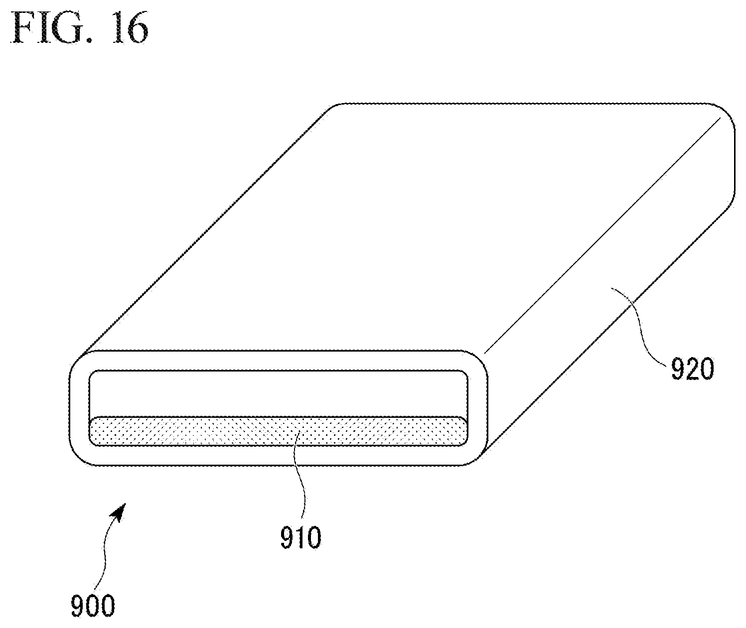
[0050] FIG. 16 is an external view of a porous copper composite member according to one of other embodiments of the invention.
EMBODIMENTS FOR CARRYING OUT THE INVENTION
[0051] Hereinafter, a description will be provided for a porous copper body, a porous copper composite member, a method for producing the porous copper body, and a method for producing the porous copper composite member according to embodiments of the invention with reference to the accompanying drawings.
First Embodiment
[0052] First, a description will be provided of a porous copper body 10 according to a first embodiment of the invention with reference to FIG. 1 to FIG. 6.
[0053] As shown in FIG. 1, the porous copper body 10 according to this embodiment includes a skeleton 12 in which a plurality of copper fibers 11 are sintered.
[0054] In the porous copper body 10 of this embodiment, a porosity P is in a range of 50% to 95%. The porosity P is calculated by the following expression.
P(%)=(1-(m/(V.times.D.sub.T))).times.100 [0055] m: Mass (g) of porous copper body 10 [0056] V: Volume (cm.sup.3) of porous copper body 10 [0057] D.sub.T: True density (g/cm.sup.3) of copper fibers 11 forming porous copper body 10
[0058] Further, in the porous copper body 10 according to this embodiment, a relative tensile strength S/D.sub.A (N/mm.sup.2) obtained by normalizing a tensile strength S (N/mm.sup.2) with an apparent density ratio D.sub.A is 10.0 or greater. The apparent density ratio D.sub.A is calculated by the following expression.
D.sub.A=m/(V.times.D.sub.T)
[0059] The copper fibers 11 forming the skeleton 12 consist of copper or a copper alloy, and a diameter R is in a range of 0.01 mm to 1.0 mm, and a ratio L/R of a length L to the diameter R is in a range of 4 to 200. In this embodiment, the copper fibers 11 consist of, for example, C1020 (oxygen-free copper).
[0060] Furthermore, in this embodiment, the copper fiber 11 is subjected to shape imparting such as twisting and bending. In addition, in the porous copper body 10 according to this embodiment, an apparent density ratio D.sub.A is 0.50 or less of a true density D.sub.T of the copper fibers 11. A shape of the copper fiber 11 is an arbitrary shape such as a linear shape and a curved shape as long as the apparent density ratio D.sub.A is 0.50% or less of the true density D.sub.T of the copper fibers 11. However, in the case where copper fibers 11 in which at least a part thereof is subjected to a predetermined shape imparting processing such as twisting processing and bending processing are used, it is possible to form voids between the copper fibers 11 in a three-dimensional and isotropic shape. As a result, it is possible to improve isotropy in various characteristics such as strength, heat transfer characteristics, and conductivity of the porous copper body 10.
[0061] The copper fibers 11 are produced through adjustment into a predetermined diameter R by a drawing method, a coil cutting method, a wire cutting method, a melting spraying method, and the like, and length adjustment for satisfying predetermined L/R by cutting.
[0062] The diameter R is a value that is calculated on the basis of a cross-sectional area A of each fiber, and is defined by the following expression on the assumption that the cross-sectional shape is a perfect circle regardless of an actual cross-sectional shape.
R=(A/.pi.).sup.1/2.times.2
[0063] In the copper fibers 11 forming the skeleton 12, the circularity C of a cross section orthogonal to the length direction is in a range of 0.2 to 0.9.
[0064] The circularity C is defined by the following expression when a cross-sectional area of the copper fiber 11 is represented as A and a circumferential length of the cross section of the copper fiber 11 is represented as Q.
Circularity C=(4.pi.A).sup.0.5/Q
[0065] In the case of a perfect circle, the circularity C is 1. As the circumferential length Q is longer than the cross-sectional area A, the circularity C becomes smaller. Accordingly, in the case where the cross section has a shape of a concave polygon such as a star shape or in the case where the cross section has a shape having a large aspect ratio, the circularity C decreases.
[0066] FIG. 2 shows a graph showing the circularity C of the regular polygon, and FIG. 3 shows a graph showing a relationship between the aspect ratio and the circularity C in a rectangular cross section.
[0067] As shown in FIG. 2, in the case of a regular polygon, when the circularity C is in a range of 0.2 to 0.9, it is an equilateral triangle and a square.
[0068] In addition, in the case of a rectangular shape, when the circularity C is in a range of 0.2 to 0.9, it is the case where the aspect ratio (long side length/short side length) is 80 or less.
[0069] In this embodiment, as shown in FIG. 4, the copper fibers 11 forming the skeleton 12 are assumed to have a substantially triangular cross-sectional shape.
[0070] In the case where the diameter R of the copper fiber 11 is less than 0.01 mm, a bonding area between the copper fibers 11 is small, and thus there is a concern that sintering strength may be deficient. On the other hand, in the case where the diameter R of the copper fiber 11 is greater than 1.0 mm, the number of contact points at which the copper fibers 11 come into contact with each other is deficient, and thus there is a concern that the sintering strength may also be deficient.
[0071] In view of these, in this embodiment, the diameter R of the copper fiber 11 is set to be in a range of 0.01 mm to 1.0 mm. Furthermore, it is preferable that the lower limit of the diameter R of the copper fiber 11 is set to be 0.03 mm or greater, and the upper limit of the diameter R of the copper fiber 11 is set to be 0.5 mm or less so as to further improve the strength.
[0072] In addition, in the case where the ratio L/R of the length L to the diameter R of the copper fiber 11 is less than 4, when the copper fibers 11 are laminated, it is difficult to set the bulk density D.sub.P to be 50% or less of the true density DT of the copper fibers 11, and thus there is a concern that it is difficult to obtain the porous copper body 10 having high porosity P. On the other hand, in the case where the ratio L/R of the length L to the diameter R of the copper fiber 11 is greater than 200, when the copper fibers 11 are laminated, it is difficult to uniformly disperse the copper fibers 11, and thus there is a concern that it is difficult to obtain the porous copper body 10 having a uniform porosity P.
[0073] In view of these, in this embodiment, the ratio L/R of the length L to the diameter R of the copper fiber 11 is set to be in a range of 4 to 200. Furthermore, it is preferable that the lower limit of the ratio L/R of the length L to the diameter R of the copper fiber 11 is set to be 10 or greater so as to further improve the porosity P. In addition, it is preferable that the upper limit of the ratio L/R of the length L to the diameter R of the copper fiber 11 is set to be 100 or less so as to obtain the porous copper body 10 having a more uniform porosity P.
[0074] Further, in the case where the cross-sectional shape of the copper fiber 11 forming the skeleton 12 is a concave polygonal shape such as a star shape and the circularity C is less than 0.2, unevenness of a surface of the copper fiber 11 is large and contacting portions between the copper fibers 11 are not secured, and thus there is a concern that the strength of the porous copper body 10 after sintering may be deficient. In addition, in the case where, in the cross-sectional shape of the copper fiber 11 forming the skeleton 12, the aspect ratio between the long side and the short side becomes large and the circularity C becomes less than 0.2, the copper fiber 11 becomes a foil shape, and thus it becomes difficult to form voids between the copper fibers 11 at the time of filling; and as a result, there is a concern that the porosity P of the porous copper body 10 after sintering may decrease.
[0075] On the other hand, in the case where the circularity C of the cross section of the copper fiber 11 forming the skeleton 12 is greater than 0.9, the cross-sectional shape approaches a perfect circle, and thus the contacting portions between the copper fibers 11 at the time of filling are in point contact. Therefore, bonding strength of the copper fibers 11 at each contact point decreases, and as a result, there is a concern that the strength of the porous copper body 10 after sintering may be deficient.
[0076] In a three-dimensional network structure formed by bonding metal fibers together, since tensile strength is strongly influenced by portions where bonding strength between fibers is weak, it is considered that when a contact point at which bonding strength is weak is formed by point contact, destruction progresses from this contact point as a starting point at the time of tension.
[0077] In view of these, in this embodiment, the circularity C of the cross section of the copper fiber 11 forming the skeleton 12 is set to be in a range of 0.2 to 0.9. Furthermore, it is preferable that the lower limit of the circularity C of the cross section of the copper fiber 11 forming the skeleton 12 is set to be 0.3 or greater, and the upper limit thereof is set to be 0.85 or less so as to further improve the porosity P and strength.
[0078] Next, a description will be provided of a method for producing the porous copper body 10 according to this embodiment with reference to the flowchart in FIG. 5, the process diagram of FIG. 6, and the like.
[0079] First, as shown in FIG. 6, the above-described copper fibers 11 are distributed from a distributor 31 toward an inside of a graphite container 32 to bulk-fill the graphite container 32. Thereby, the copper fibers 11 are laminated (copper fiber lamination step S01).
[0080] In the copper fiber lamination step S01, a plurality of the copper fibers 11 are laminated so that a bulk density D.sub.P after the filling becomes 40% or less of the true density D.sub.T of the copper fibers 11. Furthermore, in this embodiment, shape imparting processing such as twisting processing and bending processing is carried out with respect to copper fibers 11, and thus it is possible to secure a three-dimensional and isotropic voids between the copper fibers 11 during lamination.
[0081] Next, the copper fibers 11, with which the graphite container 32 is bulk-filled, are charged into an atmosphere furnace 33 and sintered by heating in a reducing atmosphere, an inert gas atmosphere, or a vacuum atmosphere (sintering step S02).
[0082] Heating conditions of the sintering step S02 in this embodiment are as follows. Specifically, a holding temperature is set to be in a range of 500.degree. C. to 1050.degree. C., and holding time is set to be in a range of 5 minutes to 600 minutes.
[0083] In the case where the holding temperature in the sintering step S02 is lower than 500.degree. C., there is a concern that a sintering rate is slow and thus sintering may not proceed sufficiently. On the other hand, in the case where the holding temperature in the sintering step S02 is higher than 1050.degree. C., there is a concern that heating may be performed at a temperature near the melting point of copper, and thus a decrease in strength and porosity P may occur.
[0084] In view of these, in this embodiment, the holding temperature in the sintering step S02 is set to be in a range of 500.degree. C. to 1050.degree. C. Furthermore, in the sintering step S02, it is preferable that the lower limit of the holding temperature is set to be 600.degree. C. or higher, and the upper limit of the holding temperature is set to be 1000.degree. C. or lower so as to reliably perform the sintering of the copper fibers 11.
[0085] In addition, in the case where the holding time in the sintering step S02 is shorter than 5 minutes, there is a concern that a sintering rate is slow and thus sintering may not proceed sufficiently. On the other hand, in the case where the holding time in the sintering step S02 is longer than 600 minutes, there is a concern that thermal shrinkage may increase and strength may decrease due to the sintering. In view of these, in this embodiment, the holding time in the sintering step S02 is set to be in a range of 5 minutes to 600 minutes. Furthermore, in the sintering step S02, it is preferable that the lower limit of the holding time is set to be 10 minutes or longer and the upper limit of the holding time is set to be 180 minutes or shorter so as to reliably perform the sintering of the copper fibers 11.
[0086] Further, as the atmosphere in the sintering step S02, a reducing gas such as a hydrogen gas, an RX gas, an ammonia decomposition gas, a nitrogen-hydrogen mixed gas, and an argon-hydrogen mixed gas may be used, and an inert gas such as a nitrogen gas and an argon gas may also be used. Further, a vacuum atmosphere of 100 Pa or less may also be used.
[0087] The sintering progresses at the contacting portion between the copper fibers 11 through the sintering step S02, and the copper fibers 11 are bonded to each other to form a skeleton 12.
[0088] In this embodiment, since the sintering step S02 is carried out in a reducing atmosphere, an inert atmosphere, and a vacuum atmosphere without pressurizing as described above, a bulk shape and a surface shape of the copper fiber 11 do not change significantly, and the circularity C of the cross section hardly changes before and after sintering.
[0089] According to the porous copper body 10 of this embodiment having this configuration, the copper fibers 11, in which the diameter R is in a range of 0.01 mm to 1.0 mm and the ratio L/R of the length L to the diameter R is in a range of 4 to 200, are sintered to form the skeleton 12, and thus sufficient voids are secured between the copper fibers 11, and a shrinkage rate during the sintering can be suppressed to a low level. Accordingly, it is possible to attain high porosity P and excellent dimensional accuracy.
[0090] In this embodiment, since the circularity C of the cross section of the copper fiber 11 forming the skeleton 12 is in a range of 0.2 to 0.9, the contact area between the copper fibers 11 is secured and the strength after sintering can be enhanced. Also, it is possible to secure voids between the copper fibers 11 and to increase the porosity P.
[0091] Accordingly, according to this embodiment, it is possible to provide the porous copper body 10 having a porosity P of 50% to 95% which is high and having excellent strength.
Second Embodiment
[0092] Next, a description will be provided of a porous copper composite member 100 according to a second embodiment of the invention with reference to the accompanying drawings.
[0093] FIG. 7 shows the porous copper composite member 100 according to this embodiment. The porous copper composite member 100 includes: a copper plate 120 (member main body) consisting of copper or a copper alloy; and a porous copper body 110 that is bonded to a surface of the copper plate 120.
[0094] In the porous copper body 110 according to this embodiment, a plurality of copper fibers are sintered and a skeleton is formed in the same manner as in the first embodiment. In the porous copper body 110 according to this embodiment, the porosity P is in a range of 50% to 95%.
[0095] The copper fibers forming the skeleton consist of copper or a copper alloy, and a diameter R is in a range of 0.01 mm to 1.0 mm, and a ratio L/R of a length L to the diameter R is in a range of 4 to 200. In this embodiment, the copper fibers consist of, for example, C1020 (oxygen-free copper).
[0096] In the copper fibers forming the skeleton, the circularity C of the cross section orthogonal to the length direction is in a range of 0.2 to 0.9.
[0097] Furthermore, in this embodiment, the copper fibers are subjected to shape imparting such as twisting and bending. In addition, in the porous copper body 110 according to this embodiment, an apparent density ratio D.sub.A is 50% or less of a true density D.sub.T of the copper fibers.
[0098] Next, a description will be provided of a method for producing the porous copper composite member 100 according to this embodiment with reference to a flowchart in FIG. 8.
[0099] First, the copper plate 120 that is a member main body is prepared (copper plate disposing step S100). Next, copper fibers are dispersed and laminated on a surface of the copper plate 120 (copper fiber lamination step S101). In the copper fiber lamination step S101, a plurality of the copper fibers are laminated so that a bulk density D.sub.P becomes 40% or less of the true density D.sub.T of the copper fibers.
[0100] Next, the copper fibers laminated on the surface of the copper plate 120 are sintered to form the porous copper body 110, and the porous copper body 110 and the copper plate 120 are bonded to each other (sintering and bonding step S102).
[0101] Heating conditions of the sintering and bonding step S102 in this embodiment are as follows. Specifically, a holding temperature is set to be in a range of 500.degree. C. to 1050.degree. C., and holding time is set to be in a range of 5 minutes to 600 minutes.
[0102] Further, as the atmosphere in the sintering and bonding step S102, a reducing atmosphere, an inert gas atmosphere, or a vacuum atmosphere is used. Specifically, a reducing gas such as a hydrogen gas, an RX gas, an ammonia decomposition gas, a nitrogen-hydrogen mixed gas, and an argon-hydrogen mixed gas may be used, and an inert gas such as a nitrogen gas and an argon gas may also be used. Further, a vacuum atmosphere of 100 Pa or less may also be used.
[0103] Through the sintering and bonding step S102, the copper fibers are sintered together to form the porous copper body 110, and the copper fibers and the copper plate 120 are sintered to bond the porous copper body 110 and the copper plate 120. Accordingly, the porous copper composite member 100 according to this embodiment is produced.
[0104] According to the porous copper composite member 100 of this embodiment having this configuration, since the circularity C of the cross section of the copper fiber forming the porous copper body 110 is in a range of 0.2 to 0.9, the contact area between the copper fibers is secured and the strength can be enhanced. Also, it is possible to secure voids between the copper fibers and to increase the porosity P of the porous copper body 110.
[0105] As a result, it is possible to greatly improve various characteristics such as heat exchange efficiency, water retention, and evaporation efficiency, when the porous copper composite member 100 is used as a heat exchanging member such as an evaporator or the like.
[0106] In addition, in accordance with the method for producing the porous copper composite member 100 according to this embodiment, the copper fibers are laminated on the surface of the copper plate 120 consisting of copper or a copper alloy, and the sintering and bonding are simultaneously performed through the sintering and bonding step S102, and thus it is possible to simplify a producing process.
[0107] Hereinbefore, description has been given of the embodiments of the invention, but the present invention is not limited thereto, and approximate modifications can be made in a range not departing from the technical features of the invention.
[0108] For example, description has been given of the case where the porous copper body is produced by using a producing facility shown in FIG. 6. However, the present invention is not limited thereto, and the porous copper body may be produced by using other producing facilities.
[0109] In addition, in this embodiment, description has been given of the case where the copper fibers consisting of oxygen-free copper (JIS C1020) are used. However, the present invention is not limited thereto, and pure copper such as phosphorus-deoxidized copper (JIS C1201, C1220) and tough pitch copper (JIS C1100) and a highly conductive copper alloy such as Cr copper (C18200) or Cr--Zr copper (C18150) may also be used.
[0110] Further, in the second embodiment, a bonding method in which a sintered layer is formed at the bonded portion of the porous copper body and the member main body has been exemplified as a desirable method. However, the present invention is not limited thereto, and the porous copper body and the member main body may also be bonded by using a bonding method such as various welding methods (laser welding method and resistance welding method) or a brazing method in which a brazing material having a low melting temperature is used.
[0111] In addition, in the second embodiment, the porous copper composite member having a structure shown in FIG. 7 is described as an example. However, the present invention is not limited thereto, and it is also possible to employ a porous copper composite member having a structure as shown in FIG. 9 to FIG. 14.
[0112] For example, as shown in FIG. 9, it is also possible to employ a porous copper composite member 200 having a structure in which as a member main body, a plurality of copper tubes 220 are inserted into a porous copper body 210.
[0113] Alternatively, as shown in FIG. 10, it is also possible to employ a porous copper composite member 300 having a structure in which as a member main body, a copper tube 320 curved in a U-shape is inserted into a porous copper body 310.
[0114] In addition, as shown in FIG. 11, it is also possible to employ a porous copper composite member 400 having a structure in which a porous copper body 410 is bonded to an inner peripheral surface of a copper tube 420 that is a member main body.
[0115] In addition, as shown in FIG. 12, it is also possible to employ a porous copper composite member 500 having a structure in which a porous copper body 510 is bonded to an outer peripheral surface of a copper tube 520 that is a member main body.
[0116] In addition, as shown in FIG. 13, it is also possible to employ a porous copper composite member 600 having a structure in which porous copper bodies 610 are bonded to an inner peripheral surface and an outer peripheral surface of a copper tube 620 that is a member main body.
[0117] In addition, as shown in FIG. 14, it is also possible to employ a porous copper composite member 700 having a structure in which porous copper bodies 710 are bonded to both surfaces of a copper plate 720 that is a member main body.
[0118] Further, as shown in FIG. 15, it is also possible to employ a porous copper composite member 800 having a structure in which a porous copper body 810 is bonded to an inner passage of a copper tube 820 that is a member main body.
[0119] In addition, as shown in FIG. 16, it is also possible to employ a porous copper composite member 900 having a structure in which a porous copper body 910 is bonded to both surfaces of a flat copper tube 920 that is a member main body.
EXAMPLES
[0120] Hereinafter, a description will be provided of results of a confirmation experiment that is carried out to confirm the effects of the invention.
[0121] Porous copper sintered bodies having a width of 30 mm, a length of 200 mm, and a thickness of 5 mm were produced by using sintering raw materials (copper fibers) shown in Table 1 in accordance with the producing method described in the above-described embodiment. The diameter R, the ratio L/R of a length L to the diameter R, and the circularity C of the copper fiber to be used as a raw material were measured as follows.
[0122] In addition, with regard to the obtained porous copper sintered body, the diameter R, the ratio L/R of the length L to the diameter R, and the circularity C of the cross section of the copper fiber forming the skeleton, the porosity, and the tensile strength were evaluated as follows. Evaluation results are shown in Table 2.
(Diameter R of Copper Fiber)
[0123] Cross sections orthogonal to the length direction of the copper fibers to be used as a sintering raw material and the copper fibers sampled from the porous copper sintered body were respectively observed with an optical microscope, and equivalent circle diameters (Heywood diameters) R=(A/.pi.).sup.0.5.times.2 were calculated by image processing using captured images, and a simple average value of the equivalent circle diameters was calculated. This was used as the diameter R of the copper fiber.
(Ratio L/R Between Length L and Diameter R)
[0124] The copper fibers to be used as the sintering raw material and the copper fibers sampled from the porous copper sintered body were respectively subjected to image analysis using a particle analyzer "Morphologi G3" manufactured by Malvern Instruments Co., Ltd., and thereby, the lengths of the copper fibers were measured, and the calculated simple average value thereof was used as the length L of the copper fiber. Using these, the ratio L/R of the length L to the diameter R was calculated.
(Circularity C in Cross Section)
[0125] Cross sections orthogonal to the length direction of the copper fibers to be used as the sintering raw material and the copper fibers sampled from the porous copper sintered body were respectively observed with an optical microscope. Simple average values of a cross-sectional area A (mm.sup.2) and a circumferential length Q (mm) were calculated by image processing using the captured images, and by using the simple average values thereof, the circularity was calculated in accordance with the following expression.
Circularity C=(4.pi.A).sup.0.5/Q
(Porosity P)
[0126] The true density D.sub.T (g/cm.sup.3) was measured by Archimedes' principle using the precision balance, and the porosity P was calculated by the following expression. The mass of the porous copper sintered body was represented as m (g), and the volume of the porous copper sintered body was represented as V (cm.sup.3).
Porosity P(%)=(1-(m/(V.times.D.sub.T))).times.100
(Tensile Strength)
[0127] The obtained porous copper sintered body was processed into a test piece having a width of 10 mm, a length of 100 mm, and a thickness of 5 mm, and then the test piece was subjected to a tensile test using universal testing machines to measure the maximum tensile strength S (N/mm.sup.2). Since the maximum tensile strength obtained by the measurement varies depending on an apparent density, in this example, a value (S/D.sub.A) obtained by normalizing the maximum tensile strength S with the apparent density ratio D.sub.A was defined as a relative tensile strength. The apparent density ratio D.sub.A was calculated by the following expression.
D.sub.A(N/mm.sup.2)=m/(V.times.D.sub.T)
TABLE-US-00001 TABLE 1 Copper fiber Sintering condition Diameter R Cross-sectional shape Temperature Time Material (mm) L/R Circularity Remarks Atmosphere (.degree. C.) (min) Present 1 C1100 0.015 5 0.68 Substantially H.sub.2 900 60 Example triangular 2 C1100 0.015 50 0.68 Substantially H.sub.2 900 60 triangular 3 C1100 0.015 100 0.68 Substantially H.sub.2 900 60 triangular 4 C1220 0.15 10 0.25 Star shape N.sub.2--3%H.sub.2 600 120 5 C1220 0.15 30 0.25 Star shape N.sub.2--3%H.sub.2 600 120 6 C1220 0.15 150 0.25 Star shape N.sub.2--3%H.sub.2 600 120 7 C1020 1.00 50 0.88 Substantially Ar 1050 10 square 8 C1020 1.00 100 0.88 Substantially Ar 1050 10 square 9 C1020 1.00 200 0.88 Substantially Ar 1050 10 square 10 C1201 0.30 20 0.38 Rectangular Vacuum 500 500 11 C1201 0.30 50 0.38 Rectangular Vacuum 500 500 12 C1201 0.30 70 0.38 Rectangular Vacuum 500 500 Present 13 C1020 0.50 50 0.51 Substantially RX gas 700 90 Example elliptic 14 C1020 0.50 100 0.51 Substantially RX gas 700 90 elliptic 15 C1020 0.50 150 0.51 Substantially RX gas 700 90 elliptic Comparative 1 C1100 0.008 20 0.78 Substantially N.sub.2--3%H.sub.2 1000 30 Example triangular 2 C1100 1.20 100 0.88 Substantially N.sub.2--3%H.sub.2 1000 30 square 3 C1100 0.03 2 0.65 Substantially N.sub.2--3%H.sub.2 1000 30 elliptic 4 C1100 0.10 300 0.85 Substantially N.sub.2--3%H.sub.2 1000 30 elliptic 5 C1220 0.08 40 0.95 Substantially Ar 800 60 circular 6 C1220 0.05 70 0.15 Star shape Ar 800 60 7 C1100 0.30 35 0.18 Rectangular Ar 800 60 * Degree of vacuum was 100 Pa or less
TABLE-US-00002 TABLE 2 Porous copper sintered body Circularity Tensile Diameter of cross Porosity strength R (mm) L/R section (%) (N/mm.sup.2) Present 1 0.015 5 0.68 54 22.6 Example 2 0.015 50 0.68 78 15.3 3 0.015 100 0.68 84 13.0 4 0.15 10 0.25 62 20.9 5 0.15 30 0.25 71 14.3 6 0.15 150 0.25 88 10.3 7 1.00 50 0.88 72 15.8 8 1.00 100 0.88 86 12.8 9 1.00 200 0.88 94 10.0 10 0.30 20 0.38 55 20.2 11 0.30 50 0.38 76 15.7 12 0.30 70 0.38 80 14.9 13 0.50 50 0.51 76 14.3 14 0.50 100 0.51 85 11.8 15 0.50 150 0.51 90 10.3 Comparative 1 0.008 20 0.78 68 8.7 Example 2 1.20 100 0.88 90 4.6 3 0.03 2 0.65 46 29.1 4 0.10 300 0.85 95 3.3 5 0.08 40 0.95 81 9.1 6 0.05 70 0.15 84 6.5 7 0.30 35 0.18 37 30.5
[0128] In any of Present Examples 1 to 15 and Comparative Examples 1 to 7, it was confirmed that there was no significant change in the diameter R, the ratio L/R between length L and diameter R, and the circularity C of the cross section between the copper fibers to be used as the sintering raw material and the copper fibers sampled from the porous copper sintered body.
[0129] In Comparative Example 1 in which the diameter R of the copper fiber was 0.008 mm and Comparative Example 2 in which the diameter R of the copper fiber was 1.20 mm, it was confirmed that the tensile strengths of the porous copper sintered bodies were low.
[0130] In addition, in Comparative Example 3 in which the ratio L/R of the length L to the diameter R of the copper fiber was 2, the porosity P was 46% which was low.
[0131] Further, in Comparative Example 4 in which the ratio L/R of the length L to the diameter R of the copper fiber was 300, the strength was low. The reason thereof is presumed to be that large voids partially existed and the strength was greatly reduced locally.
[0132] In Comparative Example 5 in which the circularity C of the cross section of the copper fiber was 0.95, the tensile strength was low. The reason thereof is presumed to be that a shape of the cross section was close to a perfect circle and the contact between the copper fibers became a point contact. In Comparative Example 6 in which the shape of the cross section of the copper fiber was a star shape and the circularity C was 0.15, the tensile strength was low. The reason thereof is presumed to be that the unevenness of the surface of the copper fiber was large, and a contact point between the copper fibers was reduced.
[0133] In Comparative Example 7 in which the shape of the cross section of the copper fiber was a rectangle and the circularity C was 0.18, the porosity was low. The reason thereof is presumed to be that the cross-sectional shape of the copper fiber became a foil shape and no gap was formed between the copper fibers.
[0134] In contrast, in the porous copper sintered bodies of the present examples, the porosity was 50% or more which was high, and the tensile strength was sufficiently secured.
[0135] From the above results, it was confirmed that, according to the invention, it is possible to provide a high quality porous copper sintered body having high porosity and sufficient strength.
EXPLANATION OF REFERENCE SIGNS
[0136] 10, 110: Porous copper body [0137] 11: Copper fiber [0138] 12: Skeleton [0139] 100: Porous copper composite member [0140] 120: Copper plate (Member main body)
* * * * *
D00000
D00001
D00002
D00003
D00004
D00005
D00006
D00007
D00008
D00009
XML
uspto.report is an independent third-party trademark research tool that is not affiliated, endorsed, or sponsored by the United States Patent and Trademark Office (USPTO) or any other governmental organization. The information provided by uspto.report is based on publicly available data at the time of writing and is intended for informational purposes only.
While we strive to provide accurate and up-to-date information, we do not guarantee the accuracy, completeness, reliability, or suitability of the information displayed on this site. The use of this site is at your own risk. Any reliance you place on such information is therefore strictly at your own risk.
All official trademark data, including owner information, should be verified by visiting the official USPTO website at www.uspto.gov. This site is not intended to replace professional legal advice and should not be used as a substitute for consulting with a legal professional who is knowledgeable about trademark law.