Cleaning Nozzle For Upholstery For Use With A Surface Cleaning Apparatus
Scott; Chloe ; et al.
U.S. patent application number 16/488360 was filed with the patent office on 2019-12-19 for cleaning nozzle for upholstery for use with a surface cleaning apparatus. The applicant listed for this patent is TTI (Macao Commercial Offshore Limited). Invention is credited to Edward Barrett, Tony Elkington, Chloe Scott.
| Application Number | 20190380555 16/488360 |
| Document ID | / |
| Family ID | 58544100 |
| Filed Date | 2019-12-19 |


| United States Patent Application | 20190380555 |
| Kind Code | A1 |
| Scott; Chloe ; et al. | December 19, 2019 |
CLEANING NOZZLE FOR UPHOLSTERY FOR USE WITH A SURFACE CLEANING APPARATUS
Abstract
An upholstery tool for use with a surface cleaning apparatus, the apparatus including a source of suction, wherein the tool includes a body including a dirty air inlet in a tool surface which faces a surface to be cleaned in use, wherein the dirty air inlet includes a first inlet section which extends across the surface and terminates in peripheral bleed air inlets a second inlet section which extends across the surface and terminates in peripheral bleed air inlets; and a third inlet section which fluidly connects the first and second inlet sections; and an outlet for fluid communication with the source of suction fluidly connected to the dirty air inlet.
| Inventors: | Scott; Chloe; (Sutton Coldfield West Midlands, GB) ; Elkington; Tony; (Matlock Derbyshire, GB) ; Barrett; Edward; (Wallingford Oxfordshire, GB) | ||||||||||
| Applicant: |
|
||||||||||
|---|---|---|---|---|---|---|---|---|---|---|---|
| Family ID: | 58544100 | ||||||||||
| Appl. No.: | 16/488360 | ||||||||||
| Filed: | February 9, 2018 | ||||||||||
| PCT Filed: | February 9, 2018 | ||||||||||
| PCT NO: | PCT/GB18/50363 | ||||||||||
| 371 Date: | August 23, 2019 |
| Current U.S. Class: | 1/1 |
| Current CPC Class: | A47L 11/4044 20130101; A47L 11/4094 20130101; A47L 9/02 20130101 |
| International Class: | A47L 11/40 20060101 A47L011/40; A47L 9/02 20060101 A47L009/02 |
Foreign Application Data
| Date | Code | Application Number |
|---|---|---|
| Feb 23, 2017 | GB | 1702960.4 |
Claims
1. An upholstery tool for use with a surface cleaning apparatus, the apparatus including a source of suction, wherein the tool includes: a body including a dirty air inlet in a tool surface which faces a surface to be cleaned in use, wherein the tool surface includes a forward edge, a rear edge, a left edge and a right edge, and the dirty air inlet includes: a first inlet section which extends across the surface and terminates in peripheral bleed air inlets in the left and right edges; a second inlet section which extends across the surface and terminates in peripheral bleed air inlets in the left and right edges; and a third inlet section which fluidly connects the first and second inlet sections; and an outlet for fluid communication with the source of suction fluidly connected to the dirty air inlet.
2. An upholstery tool according to claim 1, wherein the tool surface includes: a forward portion positioned forwardly of the dirty air inlet to define a part of the first inlet section; and a rearward portion positioned rearwardly of the dirty air inlet to define a part of second inlet section.
3. An upholstery tool according to claim 2 wherein the tool surface includes: first and second side portions positioned between the forward and rearward portions to define respective parts of the first and second inlet sections.
4. An upholstery tool according to claim 3, wherein the first and second side portions define respective parts of the third inlet section.
5. An upholstery tool according to claim 3, wherein the first and second side portions are positioned generally midway between the forward and rearward portions.
6. An upholstery tool according to any claim 2 wherein at least one or both of the forward and rearward portions are generally curved.
7. An upholstery tool according to claim 3, wherein the first and second side portions are generally planar.
8. An upholstery tool according to claim 2 wherein a leading edge of the forward portion is curved.
9. An upholstery tool according to claim 2 wherein a rearward edge of the rearward portion is curved.
10. An upholstery tool according to claim 1 wherein the first and second inlet sections each have a greater surface area than the third inlet section.
11. An upholstery tool according to claim 1 wherein the first inlet section is substantially linear.
12. An upholstery tool according to claim 1 wherein the second inlet section is substantially linear.
13. An upholstery tool according to claim 1 wherein the first inlet section has a substantially uniform depth.
14. An upholstery tool according to claim 1 wherein the second inlet section has a substantially uniform depth.
15. (canceled)
16. (canceled)
17. An upholstery tool according to claim 1 wherein the neck is at an angle .beta. positioned towards the rearward edge, and wherein the angle .beta. is between 30.degree. to 60.degree..
18. An upholstery tool according to claim 17 wherein the angle .beta. is between 40.degree. to 50.degree..
19. An upholstery tool according to claim 18 wherein the angle .beta. is 45.degree..
20. An upholstery tool according to claim 4, wherein the first and second side portions are positioned generally midway between the forward and rearward portions, wherein at least one or both of the forward and rearward portions are generally curved, wherein the first and second side portions are generally planar.
21. An upholstery tool according to claim 20 wherein a leading edge of the forward portion is curved, wherein a rearward edge of the rearward portion is curved, and wherein the first and second inlet sections each have a greater surface area than the third inlet section.
22. An upholstery tool according to claim 20 wherein the first inlet section is substantially linear, wherein the second inlet section is substantially linear, wherein the first inlet section has a substantially uniform depth, and wherein the second inlet section has a substantially uniform depth.
Description
FIELD
[0001] This invention relates to an upholstery tool for a surface cleaning apparatus which includes a source of suction.
BACKGROUND
[0002] Tools for use with a surface cleaning apparatus to clean surfaces are known.
[0003] For example, upholstery tools and surface cleaning apparatus including a source of suction for cleaning upholstery are known. Typically, upholstery tools are provided with a body having a dirty air inlet and a neck connected to the body having an outlet connection with the source of suction of a vacuum cleaner to permit the suctioning of dirt from the upholstery to be cleaned.
[0004] Upholstery tools are generally designed for cleaning upholstery, for example fabric on armchairs and sofas. Such fabric can be difficult to clean because it is relatively pliable in that it can move with respect to the product to which it is attached so that during cleaning a portion of the fabric may move under suction into the upholstery tool. This is commonly referred to as clamping. Other issues include having to clean in restricted spaces and crevices.
[0005] Another type of tool is known as the floor tool. Floor tools are generally larger than upholstery tools because they are designed to clean large planar surfaces, and so have relatively large planar sole plates. This makes them unsuitable for cleaning upholstery.
SUMMARY
[0006] It is desired to increase the effective cleaning area of an upholstery tool without significantly increasing the size of the tool. It is also desired to prevent or ameliorate motor burn out in the case of a blockage in the tool. It is a non-exclusive object of the present disclosure to provide these desiderata.
[0007] There is provided an upholstery tool for use with a surface cleaning apparatus, the apparatus including a source of suction, wherein the tool includes: [0008] a body including a dirty air inlet in a tool surface which faces a surface to be cleaned in use, wherein the dirty air inlet includes: [0009] a first inlet section which extends across the surface and terminates in peripheral bleed air inlets; [0010] a second inlet section which extends across the surface and terminates in peripheral bleed air inlets; and [0011] a third inlet section which fluidly connects the first and second inlet sections; and [0012] an outlet for fluid communication with the source of suction fluidly connected to the dirty air inlet.
[0013] There is also provided an upholstery tool for use with a surface cleaning apparatus, the apparatus including a source of suction, wherein the tool includes: [0014] a body including a dirty air inlet in a tool surface which faces a surface to be cleaned in use, wherein the tool surface includes a forward edge, a rear edge, a left edge and a right edge, and the dirty air inlet includes: [0015] a first inlet section which extends across the surface and terminates in peripheral bleed air inlets in the left and right edges; [0016] a second inlet section which extends across the surface and terminates in peripheral bleed air inlets in the left and right edges; and [0017] a third inlet section which fluidly connects the first and second inlet sections; and [0018] an outlet for fluid communication with the source of suction fluidly connected to the dirty air inlet.
[0019] The tool surface may include a forward portion positioned forwardly of the dirty air inlet to define a part of the first inlet section.
[0020] The tool surface may include a rearward portion positioned rearwardly of the dirty air inlet to define a part of second inlet section.
[0021] The tool surface may include first and second side portions positioned between the forward and rearward portions to define respective parts of the first and second inlet sections.
[0022] The first and second side portions may define respective parts of the third inlet section.
[0023] The first and second side portions may be positioned generally midway between the forward and rearward portions.
[0024] At least one or both of the forward and rearward portions may be generally curved.
[0025] The first and second side portions may be generally planar.
[0026] A leading edge of the forward portion may be curved.
[0027] A rearward edge of the rearward portion may be curved.
[0028] The first and second inlet sections may each have a greater surface area than the third inlet section.
[0029] The first inlet section may be substantially linear.
[0030] The second inlet section may be substantially linear.
[0031] The first inlet section may have a substantially uniform depth.
[0032] The second inlet section may have a substantially uniform depth.
BRIEF DESCRIPTION OF THE DRAWINGS
[0033] Embodiments of the invention will now be described by way of example only with reference to the accompanying figures in which:
[0034] FIG. 1 is an underside view of an upholstery tool in accordance with an embodiment of the present invention;
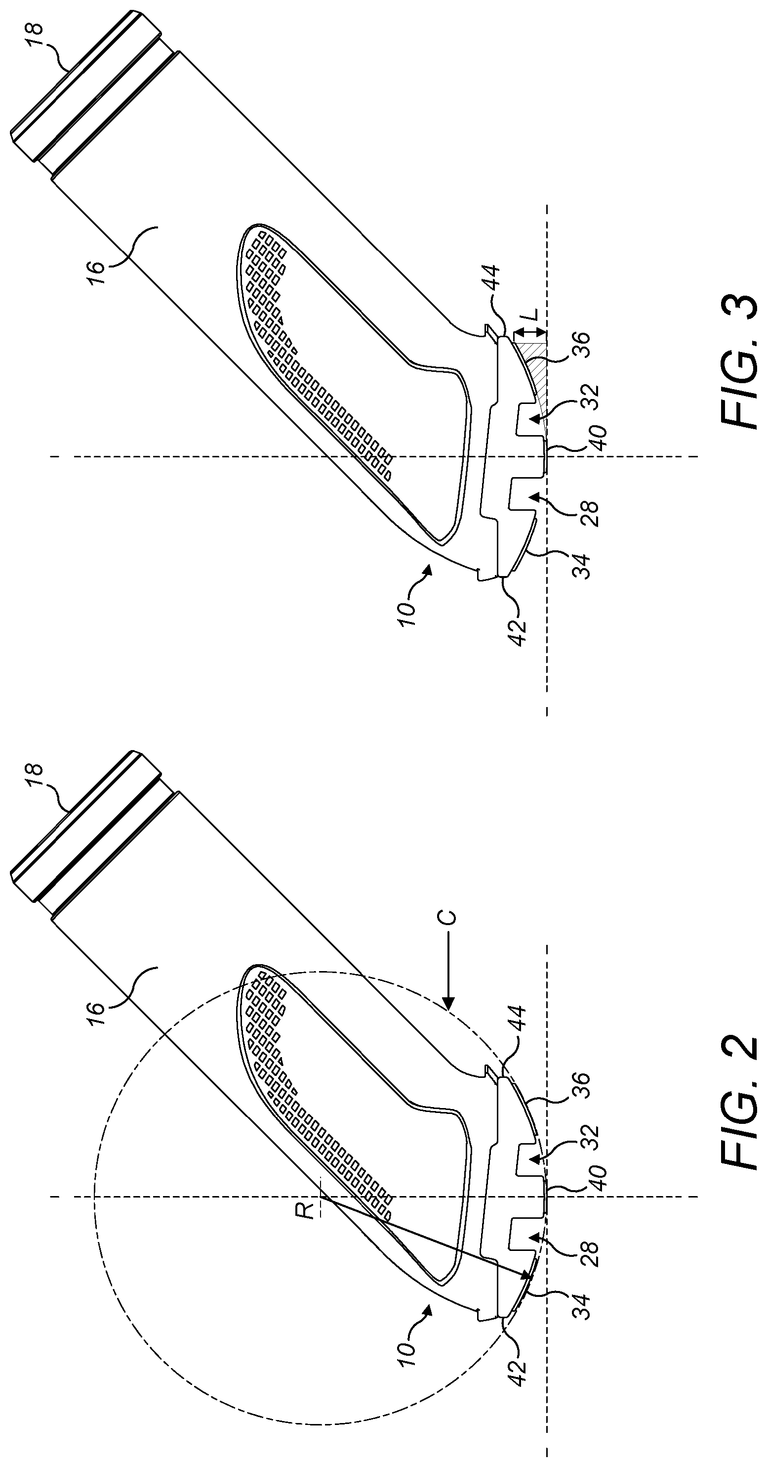
[0035] FIG. 2 is a side view of an upholstery tool of FIG. 1;
[0036] FIG. 3 is a side view of an upholstery tool of FIG. 1;
[0037] FIGS. 4 and 5 are differently annotated underside views of the upholstery tool of FIG. 1;
[0038] FIG. 6 is a front view of the upholstery tool of FIG. 1;
[0039] FIG. 7 is a front view of an optional brush attachment for use with the upholstery tool of FIG. 1;
[0040] FIG. 8 is a side view of the brush attachment of FIG. 7;
[0041] FIG. 9 is an underside view of the brush attachment attached to the upholstery tool of FIG. 1;
[0042] FIG. 10 is a front view of the brush attachment attached to the upholstery tool of FIG. 1; and
[0043] FIG. 11 is a side view of the brush attachment on the upholstery tool of FIG. 1.
DETAILED DESCRIPTION OF EMBODIMENTS
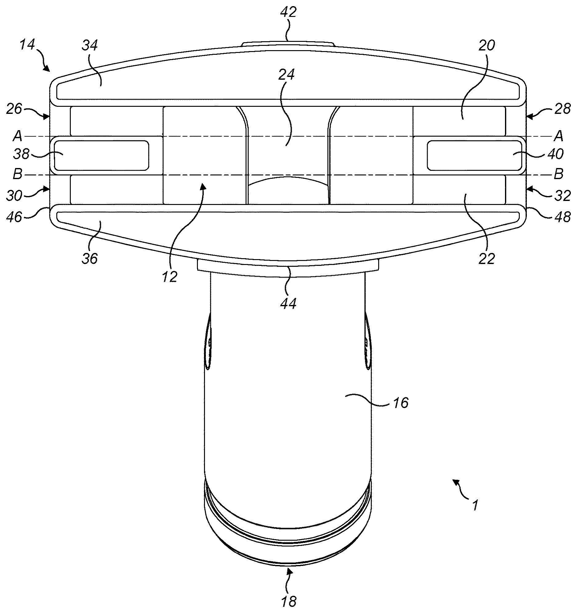
[0044] Referring to the figures, there is shown an embodiment of an upholstery tool 1. The upholstery tool 1 is for use with a surface cleaning which includes a source of suction.
[0045] The upholstery tool 1 includes a body 10 including a dirty air inlet 12 in a tool surface 14 which faces a surface to be cleaned in use. The tool 1 has an outlet 18 for fluid communication with the source of suction which is fluidly connected to the dirty air inlet 12. Attached to an upper side of the body, i.e. a surface which may be generally opposite the tool surface, a neck 16 may be provided which extends away from the body. The outlet 18 may be provided in the neck 16.
[0046] The tool surface 14 may have a forward edge 42, a rearward edge 44, a left edge 46 and a right edge 48.
[0047] The neck 16 may have a generally elongate axis which may form an angle .beta. to (a portion of) the tool surface 14. The angle .beta. may be between 30 to 60.degree.. The angle .beta. may be between 40 to 50.degree.. The angle .beta. may be 45.degree..
[0048] The angle .beta. may be positioned towards the rearward edge 44 of the tool 1.
[0049] The neck 16 may function as a handle, in use.
[0050] The combination of the angle .beta. being in the above described ranges and the neck 16 functioning as a handle means that the tool 1 may be easy to use. In particular, the tool surface 14 and the dirty air inlet 12 may be naturally presented at a convenient angle.
[0051] The dirty air inlet 12 is provided in three sections: a first inlet section 20; a second inlet section 22 and a third inlet section 24. The dirty air inlet 12 may be provided in four or more sections without departing from the scope of the present disclosure.
[0052] The first inlet section 20 extends across the tool surface 14. The first inlet section 20 terminates in peripheral bleed air inlets 26, 28. The peripheral bleed air inlets 26, 28 may be provided in respective left and right edges 46, 48 of the body 10.
[0053] The second inlet section 22 extends across the tool surface 14. The second inlet section 22 terminates in peripheral bleed air inlets 30, 32. The peripheral bleed air inlets 30, 32 may be provided in the left and right edges 46, 48.
[0054] Such an upholstery tool may be particularly advantageous. In particular, such a construction can provide a particularly effective tool. For example, the four bleed air inlets 26, 28, 30, 32 can help to reduce clamping, whilst still providing good flow of air over the surface being cleaned.
[0055] The first inlet section 20 may be substantially linear. The first inlet section 20 may have a substantially uniform depth. The first inlet section 20 may be curved.
[0056] The first inlet section 20 may have a varying depth. In particular, the first inlet section 20 may have a depth which reduces as it extends towards the peripheral air bleed inlets 26, 28.
[0057] Such arrangements have been found to appropriately distribute the source of suction within the first inlet 20 across the dirty air inlet 12 to effectively carry dirt away from the surface to be cleaned.
[0058] The second inlet section 22 may be substantially linear. The second inlet section 22 may have a substantially uniform depth. The second inlet section 22 may be curved.
[0059] The second inlet 22 section may have a varying depth. In particular, the second inlet section 22 may have a depth which reduces as it extends towards the peripheral air bleed inlets 30, 32.
[0060] Again, such arrangements have been found to appropriately distribute the source of suction within the second inlet 22 across the dirty air inlet 12 to effectively carry dirt away from the surface to be cleaned.
[0061] The third inlet section 24 fluidly connects the first and second inlet sections 20, 22. The third inlet section 24 may be provided between the first and second inlet sections in a generally central area of the tool surface 14, as shown in FIG. 1.
[0062] The tool surface 14 may include a forward portion 34 which is positioned forwardly of the dirty air inlet 12 to define a part of the first inlet section 20.
[0063] The tool surface may include a rearward portion 36 positioned rearwardly of the dirty air inlet 12 to define a part of the second inlet section 22.
[0064] The tool surface 14 may include first and second side portions 38, 40 positioned between the forward 34 and rearward 36 portions to define respective parts of the first and second inlet sections 20, 22.
[0065] The first and second side portions 38, 40 may be at peripheral regions of the dirty air inlet 12. For example, they may be positioned at a left and a right edge 46, 48 of the tool, respectively.
[0066] The forward portion 34 may be provided with a thread lifting material. The rearward portion 36 may be provided with a thread lifting material. The first side portion 38 may be provided with a thread lifting material. The second side portion 40 may be provided with a thread lifting material.
[0067] The thread lifting materials (if present) may be orientated in particular directions, as discussed in more detail below.
[0068] The first and second side portions 38, 40 may define respective parts of the third inlet section 24. In particular, with reference to FIG. 1, the third inlet section may be partly defined by lines A and B which are imaginary lines showing how part of the first and second inlet sections extend across the tool, and may also be partly defined by the first and second side portions.
[0069] The dirty air inlet may extend a distance X1 between the forward portion and the rearward portion. X1 may be between 15 mm and 35 mm. X1 may be between 20 mm and 30 mm. X1 may be approximately 25 mm.
[0070] The first inlet section may extend a distance X2 between the forward portion and the first and second side portions. X2 may be between 5 mm and 13 mm. X2 may be between 7 mm and 11 mm. X2 may be approximately 9 mm.
[0071] The second inlet section may extend a distance X3 between the rearward portion and the first and second side portions. X3 may be between 5 mm and 13 mm. X3 may be between 7 mm and 11 mm. X3 may be approximately 9 mm.
[0072] The third inlet section may extend a distance Y1 between the first and second side portions. Y1 may be between 57 mm and 65 mm. Y1 may be between 59 mm and 63 mm. Y1 may be approximately 61 mm.
[0073] The first and second side portions 38, 40 may be positioned generally midway between the forward the rearward portions 34, 36. The first and second side portions 38, 40 may be positioned at a periphery of the surface 14. The first and second side portions may extend a distance X4 between the forward and rearward portions. X4 may be between 2 mm and 10 mm. X4 may be between 4 mm and 8 mm. X4 may be approximately 6 mm.
[0074] The forward and rearward portions 34, 36 may be generally curved. In particular, in side cross-section as shown in FIG. 2, the forward and rearward portions may lie on a curve having a radius of curvature defined by a circle C having a radius R of between 40 mm and 50 mm. The radius R may be between 43 mm and 48 mm. The radius R may be approximately 46 mm. The use of such curved forward and rearward portions in embodiments may permit advantageous cleaning of upholstery products because it can reduce the contact area between the tool surface 14 and the upholstery depending on the shape of the upholstery. It may also assist with cleaning curved upholstery surfaces.
[0075] A rearward edge 44 of the rearward portion 36 may be positioned a distance L above the first and second side portions 38, 40. A forward edge 42 of the front portion 34 may be positioned a distance L above the first and second side portions 38, 40. The distance L may be between 5 mm and 9 mm. The distance L may be approximately 7 mm.
[0076] The first and second side portions 38, 40 may be generally planar. Alternatively, they may be generally curved. In particular, in side cross-section as shown in FIG. 2, the first and second side portions 38, 40 may lie on a curve having a radius of curvature defined by the circle C having a radius R of between 40 mm and 50 mm. The radius R may be between 43 mm and 48 mm. The radius R may be approximately 46 mm.
[0077] The leading, or forward, edge of the forward portion 34 may be curved. It may, alternatively, be generally linear. The forward portion may extend a distance X5 forwardly of the dirty air inlet. X5 may be between 6 mm and 14 mm. X5 may be between 8 mm and 12 mm. X5 may be approximately 10 mm.
[0078] The rearward edge 44 of the rearward portion 36 may be curved. Alternatively, the rearward edge 44 may be generally linear. The rearward portion may extend a distance X6 rearwardly of the dirty air inlet. X6 may be between 6 mm and 14 mm. X6 may be between 8 mm and 12 mm. X6 may be approximately 10 mm.
[0079] The first inlet section may have a greater surface area than the third inlet section. The second inlet section may have a greater surface area than the third inlet section. The first and second inlet sections 20, 22 may each have a greater surface area than the third inlet section 24.
[0080] One or more of the peripheral bleed inlets 26, 28, 30, 32 may have a substantially rectangular cross sectional area. Alternatively, they may (alone or in combination) have a circular cross sectional area. They may have a generally circular cross sectional area with a segment of the circle defining the cross sectional area being removed.
[0081] The peripheral bleed air inlets 26, 28, 30, 32 may have a bottom edge which faces a surface to be cleaned in use. In other words, the peripheral bleed air inlets 26, 28, 30, 32 may extend the dirty air inlet 12 from the tool surface 14 into side walls 46, 48.
[0082] The body 10 may have a width between the left and right edges 46, 48 of Y2. Y2 may be between 80 mm and 120 mm. Y2 may be between 90 mm and 110 mm. Y2 may be approximately 105 mm.
[0083] Referring to FIGS. 7 to 11, there may be provided an optional brush attachment 50 for attachment to the upholstery tool 1. The brush attachment 50 may be provided with bristles 52 which provide a substantially planar cleaning surface, by providing bristles of varying lengths. The bristles 52 may be positioned around a periphery of the tool. The attachment 50 may be provided with surfaces 56, 58 which cover the forward and rearward portions 34, 36 in use. A clip 54 may be provided to permit the brush attachment 50 to be connected to the tool 1.
[0084] It has also been found that the peripheral bleed air inlets 26, 28, 30, 32 provide the advantageous effect of permitting dirt which is positioned to the sides of the tool to be suctioned up whilst in use. This can increase the effective cleaning area of the upholstery tool 1 without increasing the size of the tool. This is advantageous as it can enable a greater effective surface area to be cleaned whilst permitting an upholstery tool 1 to fit into small spaces where other tools would not be able to fit. It also enables any dirt which is trapped in creases in the upholstery to be cleaned up effectively. If present, the thread lifting material on the forward portion 34 may extend across 90% (or more) of the width of the forward portion 34 and/or the rearward portion 36. E.g. 95% or more of the width of the forward portion 34 and/or the rearward portion 36.
[0085] If present, the thread lifting material on the rearward portion 36 may extend across 90% of the width of the forward portion 34 and/or the rearward portion 36. E.g. 95% or more of the width of the forward portion 34 and/or the rearward portion 36.
[0086] Providing such widths of thread lifting material can help to increase the useable width of the tool.
[0087] If present, the thread lifting material on each of the forward and rearward portions 34, 36 and first and second side portions 38, 40 may be provided as lint pickup strip(s).
[0088] The thread lifting material on each of the forward and rearward portions 34, 36 and first and second side portions 38, 40 may include bristles.
[0089] In some embodiments, the forward portion 34 may include bristles. The rearward portion 36 may include bristles. The first and second side portions 38, 40 may include bristles.
[0090] The bristles may be oriented in a first direction A' on the forward portion 34.
[0091] The bristles may be oriented in a second direction B' on the rearward portion 36. The bristles may be oriented in a third direction C' on the first and second side portions 38, 40.
[0092] The first direction A' and the second direction B' may be the same. The second direction B' and the third direction C' may be the same. The first direction A' and the third direction C' may be the same. The first and second and third direction A', B', C' may be the same.
[0093] However, the first direction A' and the second direction B' may be different. The second direction B' and the third direction C' may be different. The first direction A' and the third direction C' may be different. The first, second and third directions A', B', C' may be different. Any of the first, second and third directions A', B', C' may be generally opposite.
[0094] In some embodiments the first and second directions A', B' may be generally opposite whilst the first and third directions A', C' may be generally the same.
[0095] For instance, in some embodiments the first direction A' is generally rearwardly of the tool. The second direction B' is generally forwardly of the tool. The third direction C' is generally rearwardly of the tool.
[0096] Such a combination has been found to be particularly effective. In particular, the combination provides effective thread (e.g. lint) lifting from surfaces which being cleaned.
[0097] When used in this specification and claims, the terms "comprises" and "comprising" and variations thereof mean that the specified features, steps or integers are included. The terms are not to be interpreted to exclude the presence of other features, steps or components.
[0098] The features disclosed in the foregoing description, or the following claims, or the accompanying drawings, expressed in their specific forms or in terms of a means for performing the disclosed function, or a method or process for attaining the disclosed result, as appropriate, may, separately, or in any combination of such features, be utilised for realising the invention in diverse forms thereof.
* * * * *
D00000
D00001
D00002
D00003
D00004
D00005
D00006
D00007
D00008
XML
uspto.report is an independent third-party trademark research tool that is not affiliated, endorsed, or sponsored by the United States Patent and Trademark Office (USPTO) or any other governmental organization. The information provided by uspto.report is based on publicly available data at the time of writing and is intended for informational purposes only.
While we strive to provide accurate and up-to-date information, we do not guarantee the accuracy, completeness, reliability, or suitability of the information displayed on this site. The use of this site is at your own risk. Any reliance you place on such information is therefore strictly at your own risk.
All official trademark data, including owner information, should be verified by visiting the official USPTO website at www.uspto.gov. This site is not intended to replace professional legal advice and should not be used as a substitute for consulting with a legal professional who is knowledgeable about trademark law.