Breathable Mattress Foundation And Sleep System
Reynolds; Randy A.
U.S. patent application number 16/444740 was filed with the patent office on 2019-12-19 for breathable mattress foundation and sleep system. The applicant listed for this patent is Neven Sleep, LLC. Invention is credited to Randy A. Reynolds.
| Application Number | 20190380501 16/444740 |
| Document ID | / |
| Family ID | 68838827 |
| Filed Date | 2019-12-19 |


View All Diagrams
| United States Patent Application | 20190380501 |
| Kind Code | A1 |
| Reynolds; Randy A. | December 19, 2019 |
BREATHABLE MATTRESS FOUNDATION AND SLEEP SYSTEM
Abstract
Embodiments of a ventilated sleep system and an airflow/breathable mattress foundation are disclosed, and typically may be configured to provide ventilation to a mattress, for example through an upper surface of a foundation allowing airflow therethrough. Typically, sleep system embodiments may include mattresses with foam layers with ventilation passageways in fluid communication with a lower surface of the mattress cover, which is configured to allow airflow therethrough, and some embodiments may also include foam pillars. Such sleep system embodiments typically may have such a ventilation mattress atop such a ventilation foundation, with airflow therebetween.
| Inventors: | Reynolds; Randy A.; (High Point, NC) | ||||||||||
| Applicant: |
|
||||||||||
|---|---|---|---|---|---|---|---|---|---|---|---|
| Family ID: | 68838827 | ||||||||||
| Appl. No.: | 16/444740 | ||||||||||
| Filed: | June 18, 2019 |
Related U.S. Patent Documents
| Application Number | Filing Date | Patent Number | ||
|---|---|---|---|---|
| 62686458 | Jun 18, 2018 | |||
| Current U.S. Class: | 1/1 |
| Current CPC Class: | A47C 27/007 20130101; A47C 21/048 20130101; A47C 27/148 20130101; A47C 21/044 20130101; A47C 27/144 20130101; A47C 27/15 20130101 |
| International Class: | A47C 21/04 20060101 A47C021/04; A47C 27/15 20060101 A47C027/15; A47C 27/00 20060101 A47C027/00; A47C 27/14 20060101 A47C027/14 |
Claims
1. A sleep system comprising: a mattress, which comprises: a mattress cover; and one or more foam layers within the mattress cover; wherein the mattress cover comprises a bottom surface; wherein the bottom surface of the mattress cover comprises a mattress air permeable element (e.g. high airflow fabric (for example 150 gsm 100% polyester spacer fabric or mesh fabric and/or restricting airflow CFM less than about 35% at 3 PSI and/or a spacer fabric with a thickness of about 3.5 mm, a weight of about 245 g/m.sup.2, and/or an air permeability of about 636 ft3/ft2/minute at 0.018 PSI (e.g. per ASTM D737-96--Standard Test Method for Air Permeability of Textile Fabrics))); wherein the mattress is spring-free; wherein the one or more foam layers each comprise a plurality of substantially vertical air passageways which pass through the entire thickness of the corresponding foam layer; wherein the one or more foam layers comprise: a base layer of foam comprising a sculpted upper surface with a plurality of foam pillars projecting upward; a transition layer of foam with uniform thickness located atop and in contact with the upper surface of the base foam layer; a middle sculpted layer of foam having a sculpted lower surface with a plurality of foam pillars projecting downward, wherein the middle sculpted layer of foam is located atop and in contact with the transition layer of foam; and a top layer of foam with uniform thickness, which is located above the middle sculpted layer; and a mattress foundation, which comprises: a support structure; and a foundation cover comprising an upper surface; wherein the upper surface of the foundation cover comprises a foundation air permeable element (e.g. high airflow fabric (for example 150 gsm 100% polyester spacer fabric or mesh fabric and/or restricting airflow CFM less than about 35% at 3 PSI and/or a spacer fabric with a thickness of about 3.5 mm, a weight of about 245 g/m.sup.2, and/or an air permeability of about 636 ft3/ft2/minute at 0.018 PSI (e.g. per ASTM D737-96--Standard Test Method for Air Permeability of Textile Fabrics))); and wherein the mattress is located atop the foundation, and wherein the mattress and foundation are in fluid communication with each other.
2. The sleep system of claim 1, wherein the middle sculpted layer of foam further comprises a sculpted upper surface with a plurality of foam pillars projecting upward; and wherein the foam pillars of the middle sculpted layer of foam are sized within the range including 1-to-1-4-to-1 with respect to the foam pillars of the base layer of foam (such that the foam pillars of the middle sculpted foam layer each range in cross-section size from being equally sized to the base layer pillars down to being a quarter the size of the base layer pillars (i.e. four middle sculpted layer pillars per one base layer pillar)).
3. A sleep system comprising a mattress, which comprises: a cover; wherein the cover comprises a bottom surface, and wherein the bottom surface comprises an air permeable element (e.g. high airflow fabric (for example 150 gsm 100% polyester spacer fabric or mesh fabric and/or restricting airflow CFM less than about 35% at 3 PSI and/or a spacer fabric with a thickness of about 3.5 mm, a weight of about 245 g/m.sup.2, and/or an air permeability of about 636 ft3/ft2/minute at 0.018 PSI (e.g. per ASTM D737-96--Standard Test Method for Air Permeability of Textile Fabrics))).
4. The sleep system of claim 3, wherein the entire bottom surface of the mattress cover is formed of high airflow mesh fabric.
5. The sleep system of claim 3, wherein the mattress cover further comprises an upper surface, and wherein the upper surface comprises a second air permeable element (e.g. high airflow fabric (for example 150 gsm 100% polyester spacer fabric or mesh fabric and/or restricting airflow CFM less than about 35% at 3 PSI and/or a spacer fabric with a thickness of about 3.5 mm, a weight of about 245 g/m.sup.2, and/or an air permeability of about 636 ft3/ft2/minute at 0.018 PSI (e.g. per ASTM D737-96--Standard Test Method for Air Permeability of Textile Fabrics))).
6. The sleep system of claim 3, wherein the mattress further comprises one or more foam layers within the mattress cover. The sleep system of claim 6, wherein the mattress is spring-free.
8. The sleep system of claim 6, wherein the one or more foam layers (or in some embodiments, all foam layers) each comprise a plurality of substantially vertical air passageways.
9. The sleep system of claim 8, wherein the one or more foam layers comprise: a base layer of foam comprising a sculpted upper surface with a plurality of foam pillars projecting upward; a transition layer of foam with uniform thickness located atop and in contact with the upper surface of the base foam layer; a middle sculpted layer of foam having a sculpted lower surface with a plurality of foam pillars projecting downward, wherein the middle sculpted layer of foam is located atop and in contact with the transition layer of foam; and a top layer of foam with uniform thickness, which is located above the middle sculpted layer.
10. The sleep system of claim 9, wherein the middle sculpted layer of foam further comprises a sculpted upper surface with a plurality of foam pillars projecting upward.
11. The sleep system of claim 10, wherein the sculpted upper surface of the middle sculpted layer of foam comprises pillars of a different size than the sculpted lower surface of the middle sculpted layer of foam.
12. The sleep system of claim 10, wherein the foam pillars of the sculpted upper surface of the middle sculpted layer are a quarter of the size of the corresponding pillars of the sculpted lower layer of the middle sculpted layer of foam.
13. The sleep system of claim 9, wherein the foam pillars of the middle sculpted layer of foam are sized within the range including 1-to-1-4-to-1 with respect to the foam pillars of the base layer of foam (such that the foam pillars of the middle sculpted foam layer each range in cross-section size from being equally sized to the base layer pillars down to being a quarter the size of the base layer pillars (i.e. four middle sculpted layer pillars per one base layer pillar)).
14. The sleep system of claim 9, wherein the one or more foam layers further comprises a penultimate foam layer with uniform thickness located atop and in contact with the middle sculpted layer and beneath and in contact with the top layer of foam.
15. The sleep system of claim 9, wherein at least some of the substantially vertical air passageways in the foam layers align to provide continuous airflow paths from the bottom surface of the mattress to an upper surface of the mattress.
16. The sleep system of claim 3, further comprising a mattress foundation, which comprises: a support structure; and a cover comprising an upper surface, and wherein the upper surface of the foundation cover comprises a foundation air permeable element (e.g. high airflow fabric (for example 150 gsm 100% polyester spacer fabric or mesh fabric and/or restricting airflow CFM less than about 35% at 3 PSI and/or a spacer fabric with a thickness of about 3.5 mm, a weight of about 245 g/m.sup.2, and/or an air permeability of about 636 ft3/ft2/minute at 0.018 PSI (e.g. per ASTM D737-96--Standard Test Method for Air Permeability of Textile Fabrics) and/or the entire upper surface comprises such high airflow fabric)); wherein the mattress is located atop the foundation and wherein the mattress and foundation are in fluid communication with each other.
17. The sleep system of claim 16, wherein the foundation cover further comprises a port and/or a second foundation air permeable element (e.g. high airflow fabric (for example 150 gsm 100% polyester spacer fabric or mesh fabric and/or restricting airflow CFM less than about 35% at 3 PSI and/or a spacer fabric with a thickness of about 3.5 mm, a weight of about 245 g/m.sup.2, and/or an air permeability of about 636 ft3/ft2/minute at 0.018 PSI (e.g. per ASTM D737-96--Standard Test Method for Air Permeability of Textile Fabrics) and/or Polyester Non-Woven Fabric with a thickness of about 0.004 mm and/or a weight of about 1.5 oz./ft.sup.2), for example located on the lower surface of the foundation cover) for fluid communication of the foundation with the outside environment.
18. The sleep system of claim 17, further comprising an airflow unit (operable to provide forced air flow through the foundation), wherein the air flow unit is located within the support structure and cover of the foundation.
19. The sleep system of claim 18, wherein the air flow unit comprises filtration.
20. The sleep system of claim 18, wherein the air flow unit comprises a climate control unit operable to cool or heat air.
21. The sleep system of claim 8, wherein the one or more foam layers comprise two sculpted foam layers, each comprising a sculpted surface with a plurality of foam pillars.
22. The sleep system of claim 21, wherein the two sculpted foam layers comprise a lower sculpted foam layer with sculpted surface facing upward; and an upper sculpted foam layer with sculpted surface facing downward.
23. The sleep system of claim 22, wherein the upper sculpted foam layer further comprises a second sculpted surface facing upward.
Description
CROSS-REFERENCE TO RELATED APPLICATIONS
[0001] This application is a non-provisional of and claims priority to related U.S. provisional patent application Ser. No. 62/686,458 filed Jun. 18, 2018 entitled "Breathable Mattress Foundation and Sleep System".
STATEMENT REGARDING FEDERALLY SPONSORED RESEARCH OR DEVELOPMENT
[0002] Not applicable.
REFERENCE TO A MICROFICHE APPENDIX
[0003] Not applicable.
BRIEF DESCRIPTION OF THE DRAWINGS
[0004] For a more complete understanding of the present disclosure, reference is now made to the following brief description, taken in connection with the accompanying drawings and detailed description, wherein like reference numerals represent like parts.
[0005] FIG. 1A is a schematic diagram illustrating an exemplary sleep/bedding system, in which a mattress may be used atop one of two possible ventilating foundation exemplary variants;
[0006] FIG. 1B is a schematic diagram illustrating an alternate exemplary sleep/bedding system, in which a mattress may be used atop one of two possible ventilating foundation exemplary variants;
[0007] FIGS. 1Ca, 1Cb and 1Cc illustrate a detailed embodiment of a sleep/bedding system similar to that of FIG. 1B and having an internal air input unit with optional HEPA filter and an access panel, with FIG. 1Ca showing a side view, FIG. 1Cb showing an end view (from the foot of the bed), and FIG. 1Cc showing a top view;
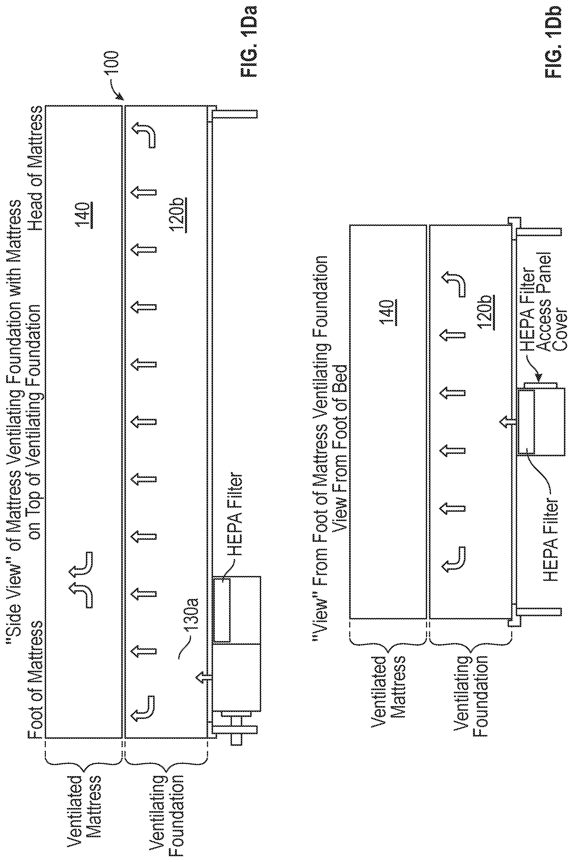
[0008] FIGS. 1Da, 1Db and 1Dc illustrate a detailed embodiment of a sleep/bedding system similar to that of FIG. 1B and having an external air input unit with optional HEPA filter and an access panel, with FIG. 1Da showing a side view, FIG. 1Db showing an end view (from the foot of the bed), and FIG. 1Dc showing a top view;
[0009] FIG. 1E illustrates a perspective view of an exemplary sleep/bedding system similar to FIGS. 1Ca, 1Cb and Cc;
[0010] FIGS. 2A1 and 2A2 illustrate an exemplary mattress embodiment (without the cover being shown, to allow viewing of internal components) which is an all-foam (e.g. spring-free) mattress configured for ventilation, with FIG. 2A1 showing an exploded perspective view of an exemplary mattress and FIG. 2A2 showing a cut-away (e.g. cross-section) elevation view of the exemplary mattress of FIG. 2A1;
[0011] FIGS. 2B1 and 2B2 illustrate an exemplary mattress embodiment (similar to that of FIG. 2A1 in configuration, but comprising different foam materials for at least some of the layers) configured for ventilation, with FIG. 2B1 showing an exploded perspective view of an exemplary mattress and FIG. 2B2 showing a cut-away (e.g. cross-section) elevation view of the exemplary mattress of FIG. 2B1;
[0012] FIG. 3 illustrates a top/plan view of an exemplary base (sculpted) layer of foam (of the sort that might be used in FIG. 2A1, for example);
[0013] FIG. 4 illustrates a bottom/plan view of an exemplary middle sculpted foam layer (of the sort that might be used in FIG. 2A1, for example);
[0014] FIGS. 5A and 5B illustrate exemplary mattress embodiments configured for ventilation;
[0015] FIGS. 6A and 6B illustrate detailed views of the middle sculpted foam layers;
[0016] FIGS. 7A and 7B illustrate alternative detailed views of the middle sculpted foam layers;
[0017] FIG. 8 illustrates an exemplary base foam layer similar to that shown and described in FIG. 3; and
[0018] FIG. 9 illustrates via a schematic cross-section diagram an exemplary sleep system having a ventilation mattress atop an airflow/breathable (e.g. ventilation) foundation.
DETAILED DESCRIPTION
[0019] It should be understood at the outset that although illustrative implementations of one or more embodiments are illustrated below, the disclosed systems and methods may be implemented using any number of techniques, whether currently known or not yet in existence. The disclosure should in no way be limited to the illustrative implementations, drawings, and techniques illustrated below, but may be modified within the scope of the appended claims along with their full scope of equivalents.
[0020] The following brief definition of terms shall apply throughout the application:
[0021] The term "comprising" means including but not limited to, and should be interpreted in the manner it is typically used in the patent context.
[0022] The term "foam" means a material in a lightweight cellular form, for example resulting from introduction of gas bubbles during manufacture to produce a consistent cell structure, and/or any of various light, porous, semirigid or spongy materials or cellular solids, usually the solidified form of a liquid full of gas bubbles, which may be used as a building material or for shock absorption, and includes open cell foams such as polyurethane foam, latex, memory foam, specialty memory foam, gel memory foam, gel latex foam or other gel foams, etc.;
[0023] The term "IFD" means indentation force deflection, and describes a well-known measurement system for foam firmness;
[0024] Directions, such as up (e.g. upward) and/or down (e.g. downward), typically are intended to be based on the mattress (or sleep system or foundation) in its normal sleeping position as understood by persons of skill; for example, the upper surface of the mattress might face the ceiling and/or serve as the sleep surface upon which the user might lie, while the bottom surface of the mattress might face the floor or ground and/or be placed atop a foundation;
[0025] The phrases "in one embodiment," "according to one embodiment," and the like generally mean that the particular feature, structure or characteristic following the phrase may be included in at least one embodiment of the present invention, and may be included in more than one embodiment of the present invention (importantly, such phrases do not necessarily refer to the same embodiment);
[0026] If the specification describes something as "exemplary" or as an "example," it should be understood that refers to a non-exclusive example:
[0027] The terms "about" or "approximately" or the like, when used with a number may mean that specific number, or alternatively, a range in proximity to the specific number, as understood by persons of skill in the art field (for example, +/-10%); and
[0028] If the specification states a component or feature "may," "can," "could," "should," "would," "preferably," "possibly," "typically," "optionally," "for example," "often," or "might" (or other such language) be included or have a characteristic, that particular component or feature is not required to be included or have the characteristic. Such component or feature may be optionally included in some embodiments, or it may be excluded.
[0029] Typical sleep or bedding systems may have a conventional (typically inner-spring) mattress located atop a conventional box spring foundation unit. In such conventional sleep systems, there is typically no interaction (e.g. airflow) between the mattress and the box spring foundation, other than the fact that the box spring foundation supports (e.g. underlies) the mattress. While conventional sleep systems may be sufficient for some sleepers/users, many users might desire and are looking for an improved sleep experience.
[0030] For example, many users might find conventional sleep systems rather hot (especially when the mattress includes foam, and most especially when the mattress includes memory foam), resulting in a rather sweaty, uncomfortable night's sleep of the sort that may result in restlessness and lack of deep slumber. Other users may have allergy problems, and a conventional mattress may, over time, collect dust and other allergens that might trouble the user during sleep. Additionally, conventional inner-spring mattresses may not support the user's body as effectively as desired, perhaps resulting in discomfort.
[0031] The presently disclosed embodiments may address one or more of these issues. For example, disclosed embodiments may provide ventilation (e.g. airflow), such that the mattress may better breathe and/or disperse heat (e.g. improving sleep comfort while a user is atop the mattress); disclosed embodiments may refresh the mattress, for example sucking out stale air with potential allergens (which could happen either when the user is atop the mattress or, alternatively, when the user is not on the mattress (for example, based on a timer)); and/or disclosed embodiments may provide superior comfort/support. Typically, disclosed embodiment sleep systems might have the mattress and foundation interact with each other (for example, being in fluid communication, for example fluid communication between the interior of the foundation and the interior of the mattress through the upper surface of the foundation and the lower surface of the mattress), to provide one or more such sleep benefits, as persons of skill will understand based on the disclosure below. Typical foundation embodiments might comprise an upper surface (of a cover) allowing airflow therethrough (and in some embodiments having an air flow unit (such as a fan or air pump) operable to direct air through the upper surface), while typical mattress embodiments might comprise a bottom surface (of a cover) (and in some embodiments a top surface of the cover) allowing airflow therethrough (and often also including air/ventilation pathways (such as pinholes) vertically throughout the mattress (for example, through an all foam mattress or through the foam layers of the mattress)). Some mattress embodiments might be configured to provide a billows effect (which may drive airflow within the mattress and/or between the mattress interior and the foundation). So, most disclosed sleep system embodiments typically might have a ventilation mattress (e.g. with a lower surface configured to allow airflow therethrough) atop a ventilation foundation (e.g. with an upper surface configured to allow airflow therethrough, which can also be termed an airflow mattress foundation), with airflow therebetween. In some embodiments, the foundation (e.g. via an air flow unit) or the mattress (e.g. via a billows effect, in which movement of the user atop the mattress causes air movement within the mattress that might drive airflow between the mattress and the corresponding foundation) might be configured to direct airflow therebetween.
[0032] Disclosed embodiments relate generally to mattress ventilation sleep systems (and/or related foundations and/or mattresses), which typically would include a mattress ventilation/breathable foundation (e.g. an airflow foundation) in conjunction with a mattress (for example, typically located atop the foundation and typically a ventilation mattress). Typically, the mattress ventilation/breathable foundation might comprise a support structure (such as support struts and structural frame, for example, which might be similar to a conventional box spring or mattress foundation), operable to support a mattress in a manner similar to a conventional mattress foundation (and which typically might be substantially hollow, for example with an open hollow cavity located between the side frame supports and the upper and lower surface slats/struts (and in some embodiments, for example depending on mattress size, one or more interior structural supports (e.g. beam(s)) spanning from one side of the frame to another and/or from the upper surface slats to the lower surface slats of the foundation)); and a cover (including an upper, support surface upon which the mattress would lay), which would typically include a means for airflow between the foundation and the supported mattress (e.g. an air permeable element/panel, such as one or more panels of high air flow fabric, which could be spacer fabric or mesh fabric, located in the upper surface of the foundation cover, for example). Some embodiments might optionally also include an air flow unit for the foundation (such as a forced air supply unit (e.g. fan) operable to either blow air into the supported mattress atop the foundation or suck air from the supported mattress). In some embodiments, such an air flow unit might include filtration (such as a HEPA filter), which might for example be located at the intake and/or outtake for the air flow unit. The air flow unit might be housed within the support structure of the foundation in some embodiments, while in other embodiments the air flow unit might be external to (for example, mounted onto) the support structure (for example, mounted onto the bottom surface of the cover/support structure and in fluid communication with the hollow cavity within the cover/support structure by an opening). For embodiments without an air flow unit, a ventilation mattress configured to provide billows effect might optionally be used atop the ventilation foundation, with the billows effect driving and/or enhancing airflow between the ventilation mattress and the ventilation (e.g. airflow) foundation (although other embodiments could use the billows effect in conjunction with an air flow unit).
[0033] Typically, the foundation cover would surround/enclose/encompass the support structure on all sides, and would include a means for airflow between the foundation and the supported mattress (e.g. air permeable element/panel, such as high airflow fabric, which could be spacer or mesh fabric, panel(s)) on at least the upper surface of the cover (e.g. the surface which is configured to support the mattress). Optionally, the lower surface of the cover (e.g. forming the underside of the foundation) would also include a similar means for airflow (e.g. between the foundation and the external atmosphere) (e.g. air permeable element/panel, such as high airflow fabric, which could be spacer fabric or mesh fabric, panel(s)). Alternatively, the cover may have some other means for airflow into the hollow cavity and/or interior of the foundation from the external environment (such as ports, vents, or other inlet(s) and/or similar means for airflow (e.g. air permeable element/panel, such as high airflow fabric, which could be spacer fabric or mesh fabric, panel(s)) on the sides and/or the use of breathable material for one or more portions of the cover other than the upper surface (e.g. a fabric material that is breathable, even if less so than a high airflow fabric panel, for example with the difference in sizing allowing for adequate airflow). In some embodiments, such high airflow fabric, which could be spacer fabric or mesh fabric, panel(s) may comprise spacer mesh/knit fabric, for example configured to restrict airflow CFM less than about 35% at 3 psi. In some embodiments, such high airflow fabric (which could be spacer fabric or mesh fabric) panels may be (inherently) fire resistant (FR--e.g. meeting US Federal Std. 1633) and/or could be treated to be FR (e.g. with a spray-on FR additive). For example, the high airflow fabric could be spacer fabric and/or could have a thickness of about 3.5 mm, a weight of about 245 g/m2, and/or an air permeability of about 636 ft3/ft2/minute at 0.018 PSI.
[0034] In other embodiments (for example, using an airflow unit) the foundation cover might be airtight/air impermeable (e.g. formed of an airtight material such as fabric overtop a polyvinyl substrate, for example) except for the attachment/fluid communication port (e.g. inlet/outlet/opening) for the air flow unit (which allows fluid communication between the external environment and the hollow cavity within the foundation, for example) and the means for airflow between the foundation and the supported mattress (e.g. air permeable element/panel, such as high airflow fabric, which could be spacer fabric or mesh fabric, panel(s)). For example, the bottom and side surfaces of the foundation cover would typically be airtight (except for the inlet/outlet/opening for the air flow unit), while the upper surface of the foundation cover (which would typically support and/or contact the bottom surface of the mattress) would include the means for airflow between the foundation (e.g. the air flow unit) and the supported mattress (e.g. at least one air permeable element/panel, such as one or more panels of high air flow fabric, which could be spacer fabric or mesh fabric, located in the upper surface of the foundation cover, for example). In some embodiments, the entire upper surface of the foundation cover might be formed of high airflow fabric, while in other embodiments, the upper surface might include a plurality of panels of such high airflow fabric and/or other means for allowing airflow between the foundation and the supported mattress (such as air passageways).
[0035] Typically, air might flow through the hollow cavity of the foundation to the upper surface of the foundation cover (as directed by the air flow unit and/or billows effect, for example), but alternatively, there could be tubing or ducts leading from the air flow unit and/or air entry means (such as the airflow means on the lower surface of the foundation) to the upper surface of the foundation cover (e.g. to specific locations on the upper surface of the foundation cover corresponding to the pinholes in the supported mattress thereupon). In such embodiments, it might not be necessary for the bottom and sides of the foundation cover to be airtight.
[0036] Additionally, some embodiments of the air flow unit might optionally comprise a climate control unit, which might cool and/or heat air flowing through the air flow unit (for example, before the air flows into the supported mattress atop the foundation). In some embodiments, the climate control unit would be located within the housing for the air flow unit, while in other embodiments, the climate control unit might be located external to such housing (e.g. it may be either separate or combined with the blower portion of the air flow unit). Similarly, embodiments of the air flow unit might optionally comprise an air ionizer (for electric sterilization of air prior to entering the foundation) and/or an ultraviolet germicidal irradiation light (for irradiating light sufficiently to substantially destroy harmful microbes, such as bacteria, prior to entering the foundation). As with the optional climate control unit, the air ionizer and/or UV germicidal irradiation light units could be located within the housing for the air flow unit or (in other embodiments) located external to such housing (e.g. each may be either separate or combined with the blower portion of the air flow unit). Typically, the air flow unit might be controlled/operated by a controller, which might be a separate device and which might allow for remote control of the air flow device (e.g. the blower and/or climate control unit). In some embodiments, the controller and/or air flow unit may include a timer, for example allowing the user to set the air flow unit for a regular (for example daily or weekly) refresh cycle. And typically, the air flow unit would be electrically powered (for example with a plug allowing power to be drawn from a standard electrical wall socket).
[0037] Without being held to any theory, Applicant believes that airflow through some ventilation mattresses and/or sleep systems may be improved based on a billows effect. For example, ventilation passageways in the mattress in fluid communication with the lower surface of the ventilation mattress (which typically has an airflow means, such as high airflow fabric (such as spacer fabric or mesh fabric)) may open and/or close based on movement of the user atop the mattress, such that the user's natural body movements while laying atop the mattress may provide a billows effect that draws/sucks air in and/or expels/blows air out of the mattress via such ventilation passageways (e.g. vertical pinholes)). The billows effect could arise from mattresses with horizontal ventilation passageways and/or vertical ventilation passageways. For example, air might be blown out of some vertical ventilation passageways (e.g. vertical pinholes) and sucked into other vertical ventilation passageways (e.g. vertical pinholes), based on air pressure gradients caused by the user's natural body movements atop the mattress (for example, foam in the mattress surrounding the ventilation passageways may compress when a user's body weight acts upon the mattress, such that user movement atop the mattress may provide a billows effect). In this way, the billows effect of such ventilation mattresses may improve air circulation through the mattress (especially when used with a ventilation foundation and/or when the vertical ventilation passageways are in fluid communication with the air flow means (e.g. high airflow mesh fabric)), which may in turn also provide cooling and/or evaporation benefits that could lead to a more comfortable sleep surface. The ventilation mattress exemplary embodiments described herein may, for example, provide such billows effect.
[0038] So typically in operation, air might be drawn into the foundation (for example by the air flow unit, through the intake opening/fluid communication port, and/or billows effect of a ventilation mattress through and/or air entry means (such as the airflow means on the lower surface of the foundation)), and then forced out the upper surface (for example through a high airflow fabric upper surface or panel(s)) and into the supported mattress. This may allow for a supported mattress to be refreshed with clean air and/or may enhance sleep comfort for a user lying atop the mattress. Alternatively, air might be sucked out of the supported mattress (for example by operating the air flow unit in reverse to create suction and/or billows effect), into the foundation (for example through the upper surface of the cover of the foundation, perhaps through one or more high air flow fabric panels), and out the air flow unit's outtake opening/fluid communication port (which might be the same intake opening if the air flow device is operated for blowing instead of suction in some embodiments) and/or air entry/exit means (such as the airflow means on the lower surface of the foundation). In some embodiments, the air flow unit might be operable to run in forward (e.g. blowing mode) and/or reverse (e.g. suction mode). So in some embodiments, the air flow unit might be run in reverse (for example, suction mode to suck air from the supported mattress) to refresh the mattress (e.g. a refresh cycle, which in some embodiments might be periodically run), while the air flow unit might be run in forward (for example, blowing mode to blow fresh (e.g. filtered) and/or climate controlled (e.g. cooled or heated) and/or ionized and/or UV sanitized air into the supported mattress) to enhance sleep comfort atop the supported mattress (for example, improving allergy conditions and/or temperature and/or airflow for the user atop the supported mattress, perhaps while the user is actually lying atop/sleeping on the mattress). For sleep systems with a ventilation mattress configured for billows effect, movement of the user atop the mattress may pump air into and/or out of the mattress through the lower surface of the mattress cover (with airflow means, such as high airflow fabric) and/or the ventilation/breathable (e.g. airflow) foundation (for example, through the upper surface of the foundation with airflow means, such as high airflow fabric (which could be spacer fabric or mesh fabric and/or could be the same as the high airflow fabric of the mattress cover), into the hollow cavity of the foundation, and/or through the lower surface of the foundation (e.g. airflow means, such as high airflow fabric), allowing for airflow between the ventilation mattress and the ventilation foundation.
[0039] While it is possible that any sort of mattress might be used to some advantage atop such a ventilation/breathable (e.g. airflow) foundation, more typically specialized airflow (e.g. ventilation) mattress embodiments might be used in conjunction with the disclosed foundation embodiments (and in some embodiments, such ventilation mattresses might be configured to provide billows effect). For example, the mattress might comprise a mattress cover having a bottom surface which includes a means for airflow between the foundation and the supported mattress (e.g. into and/or out of the mattress, for example at least one air permeable element/panel). For example, in some embodiments the bottom surface of the mattress cover might be formed of or include one or more panels of high airflow fabric, which could be spacer fabric or mesh fabric (or alternatively, the bottom surface of the mattress cover might include air passageways, which might correspond to those of the upper surface of the foundation cover). In some embodiments, the top surface of the mattress cover might also comprise an air permeable element/panel or other means of airflow into/out of the mattress (e.g. high airflow fabric (such as spacer fabric or mesh fabric) or loosely woven fabric panel(s)). And in some embodiments, the remainder of the mattress cover might be (substantially) air impermeable. Furthermore, the mattress might comprise one or more (and typically a plurality of) primarily vertical air pathways/passageways (e.g. pin holes), operable to allow air flow vertically throughout the mattress (for example from the bottom of the mattress to the top of the mattress). Some mattress embodiments might also comprise horizontal ventilation passageways. In some embodiments, the mattress might be an all-foam and/or spring-free mattress. For example, the mattress might be formed entirely of layers of foam, and each layer of foam might include vertical pin holes/vertical passageways/pathways, at least some of which align and/or are in fluid communication, for example to provide continuous airflow passages/pathways/pinholes vertically throughout the mattress (although in some embodiments, fluid communication between vertical passageways in different foam layers might be via horizontal channels/passageways).
[0040] Some such mattress embodiments might include one or more foam layers having a sculpted surface with a plurality of foam pillars. For example, some embodiments might have a base layer of foam (e.g. the bottom layer of foam) with an upward facing sculpted surface (e.g. the pillars of foam facing/projecting upward), and another layer of foam (typically a middle foam layer, located somewhere between the base foam layer and the uppermost (sleep surface) layer of foam) with a downward facing sculpted surface (e.g. the pillars of foam facing/projecting downward). Typically, the sculpted foam layers would each have scoring (e.g. a series of grooves/gaps) forming a grid on one surface (termed the sculpted surface), with the grid pattern resulting in a plurality of foam pillars projecting outward from a common, unified slab/base of foam (e.g. the surface opposite the sculpted surface typically would be flat, such that the foam pillars would all be joined together into an integral whole layer at their bases/bottoms). The sculpted foam layer(s) might effectively replace the support functionality of the springs while also often providing added benefits. For example, a sculpted foam surface (e.g. foam pillars) may provide more flexibility in adjusting to various body contours than metal springs, and therefore may be more effective in reducing pressure points against the human body than traditional metal springs in conventional mattresses. More specifically, the layer(s) of foam with a sculpted surface would typically include a plurality of foam pillars (or blocks), each of which is freestanding (e.g. independent) with respect to the other pillars, but all of which are joined together into a single integral base (which typically has a flat exterior surface). So, the base portion of the pillars are all joined together (e.g. a common base), while the remaining freestanding portion of the layer of foam comprises a plurality of independent pillars separated from one another by a gap or groove on all sides. Stated another way, the sculpted layer(s) of foam may comprise each a base portion (which typically is a uniform flat sheet of foam) and a pillar portion (which typically comprises a plurality of independent pillars or blocks of foam, each of which is completely separate from the other pillars), with the pillar portion being securely attached to a surface of the base portion (so in effect the pillars project out from the flat base portion). Thus, the sculpted surface of the sculpted layer of foam would typically be the distal surface of the pillars (or pillar portion). Typically, the sculpted layer of foam may be formed by cutting a pattern of grooves in one surface (which would then become the sculpted surface) of an initially uniform (e.g. flat sheet with constant thickness) sheet of foam, thereby forming a plurality of foam pillars which extend out from the base portion (with the pillar portion and the base portion integrally forming a single layer of foam having different shapes/characteristics on opposing sides). Thus, the sculpted layer of foam might also be termed a contour cut layer of foam in some embodiments (since in many embodiments the layer of foam is sculpted via cutting, for example contour cutting). In other embodiments, it may be possible to form the sculpted layer of foam by molding (with the mold forming the pillar portion projecting outward from the base portion). Typically, the substantially one entire surface of the sculpted foam layer (e.g. the entire sculpted surface) would be entirely comprised of such pillars (e.g. substantially the entire sculpted surface of the sculpted foam layer would be formed of pillars), although in other embodiments the sculpted surface might have pillars only on a portion of the sculpted surface.
[0041] Typical mattress embodiments might have vertical pin holes passing through (at least) the base portion of the sculpted foam layers, and such pin holes might typically be positioned to align with the grooves/gaps between the foam pillars (so that air could flow continuously through the vertical pin holes and the grooves to pass from one surface of the sculpted foam layer all the way through to the other surface of the sculpted foam layer). In some embodiments, the base layer of foam would comprise a foam component having a sculpted surface (typically with pillars facing upward) surrounded by foam edge support perimeter rails (which typically would be solid blocks of foam encompassing the sides of the base foam component with sculpted surface, and typically having an uncompressed height approximately equal to the uncompressed height of the base foam component (e.g. the upper surface of the edge support perimeter rails would typically be approximately the same as the uncompressed height of (e.g. flush with) the upper surface of the foam pillars of the base foam component with sculpted surface).
[0042] Typically, mattress embodiments would have at least one (foam) layer located between the base sculpted foam layer (which typically would have the sculpted surface (e.g. foam pillars) facing upward) and the middle sculpted foam layer (which typically would have the sculpted surface (e.g. foam pillars) facing downward), and would have at least one (foam) layer located above the middle sculpted foam layer (e.g. a sleep surface layer (typically of foam) would be located atop the middle sculpted foam layer). In some embodiments, the foam pillars of the base sculpted foam layer would be larger (e.g. the cross-section/footprint/outer surface of the pillars would be larger) than the foam pillars of the middle sculpted foam layer. And as mentioned above, typically the various (foam) layers of the mattress would each have vertical pin holes, at least some of which would align to provide continuous airflow from the bottom to the top of the mattress. For example, in some embodiments all (foam) layers located above the base layer of foam might have vertical pinholes which entirely align, even though the base foam layer might have less vertical pinholes spaced further apart such that only some of the pinholes in the remaining layers align with pinholes in the base layer. Although the base layer in some embodiments may have fewer pinholes spaced further apart than the other layers of foam, air may be operable in some such embodiments to move through the grooves in the base portion (e.g. since the pinholes in the base portion may be in fluid communication with the grooves in the base portion) to the pinholes in the upper layers of foam which are not aligned with the pinholes in the base layer of foam.
[0043] Not intending to be bound by theory, typically, the sculpted layer of foam would have a plurality of foam pillars forming the sculpted surface, and the pillars would be configured within the sculpted foam layer and the mattress as a whole to essentially be limited to movement only (or in some embodiments, primarily) in the vertical direction (e.g. without any horizontal/sideways movement of the pillars during use of the mattress). In other words, the configuration of the foam layers of the mattress (for example, with the layers placed in contact in such a way as to minimize shear or torsion in the pillars during construction (e.g. essentially placing the pillars only in compression) and with the layers perhaps laminated together) would typically ensure that compression on the top (e.g. sleep surface) of the mattress would be transmitted to the foam pillars entirely as a vertical (e.g. compression) force (without, for example, introducing any (e.g. substantial) horizontal, shear, or torsion forces to the foam pillars) for each affected foam pillar (although in some embodiments, downward movement of such foam pillars might cause closing of one or more vertical ventilation passageways in proximity to the foam pillar). Additionally, each pillar of foam in the sculpted layer would typically be configured for essentially independent movement (e.g. each pillar moves independent of the other surrounding/proximate pillars). This independence might arise due to the contour cuts (e.g. grooves/gaps) separating the foam pillars and/or the fact that the base of the foam pillars would be linked by conformable foam (e.g. in the form of an integrated base of foam linking all pillars together). So, embodiments might have pillars of the sculpted foam layer configured for essentially independent movement and/or essentially only vertical movement during usage of the mattress (e.g. by a user lying atop the mattress). Typical embodiments might have the pillars configured for independent movement essentially only in the vertical direction. For example, each foam pillar might be operable to move vertically without substantially imparting any vertical movement to surrounding/proximate foam pillars in the sculpted foam layer. Thus, movement by one foam pillar typically might not impart any movement to other foam pillars in proximity within the sculpted foam layer (such that each pillar movement would independently relate to its own loading from the sleep surface above). So, each foam pillar of an exemplary sculpted foam layer in a disclosed mattress embodiment may be operable to only (or in some embodiments primarily) carry/support compression forces from directly above the foam pillar. Of course, Applicant does not intend to be bound by theory, but rather simply notes that the presently disclosed embodiments may perform/operate differently and/or better. Such configuration of the sculpted foam layer (with regard to movement) may be quite different from the typical movement allowed/provided by conventional metal springs (e.g. coil springs in a mattress). Conventional coil spring mattresses have a series of springs which typically are linked by wire across their top surfaces. Thus, the coil springs do not move independently (e.g. movement by one coil spring necessarily affects the surrounding coil springs due to the rigid nature of the linking wire frame) and the linking wire frame at the top of the coil springs may typically introduce non-vertical (e.g. non-compression) forces into the springs (such that the coil springs may flex and move horizontally and/or torsionally, for example, in response to a user atop the mattress sleep surface). Thus, the disclosed embodiments (with foam pillars in a spring-less mattress) may perform quite differently in operation than a conventional spring mattress. Applicant notes that disclosed mattress embodiments typically do not include traditional springs, but for example might be termed all-foam mattresses (e.g. all the cushion/support elements are foam) and/or (metal/coil) spring-free mattresses (e.g. no springs, even if the mattress embodiment may include some other cushion/support element(s) in addition to or instead of one or more foam elements). So for example, a ventilation mattress configured for billows effect might comprise one or more sculpted foam layers and/or a plurality of vertical ventilation passageways (for example, passing from the lower surface of the mattress through one or more foam layers, and in some embodiments passing all the way through the mattress to its upper surface), and typically might also have a lower (cover) surface with airflow means, such as high airflow fabric (which could be spacer fabric or mesh fabric), in fluid communication with one or more of the vertical ventilation passageways.
[0044] While typical sleep system embodiments would comprise a mattress embodiment atop a foundation embodiment, other embodiments might be focused on only the mattress or only the foundation. In other words, disclosed mattress embodiments could alternatively be used with conventional foundation elements (or even separately/alone), and disclosed foundation embodiments could alternatively be used with conventional mattress elements (although doing so might reduce potential benefits available through the joint use of disclosed mattress embodiment(s) with disclosed foundation embodiment(s), since the joint use of ventilation mattress atop ventilation foundation may provide for improved fluid communication therebetween). A preferred embodiment, however, would typically place a mattress configured to allow airflow/air transfer (e.g. airflow) through its bottom surface (and perhaps also typically having some means of air distribution throughout the mattress (e.g. pinholes/passageways) for air passing through the bottom surface of the mattress) atop a foundation configured to provide airflow/air transfer (for example, forced airflow, which might be suction and/or blowing) through its upper surface.
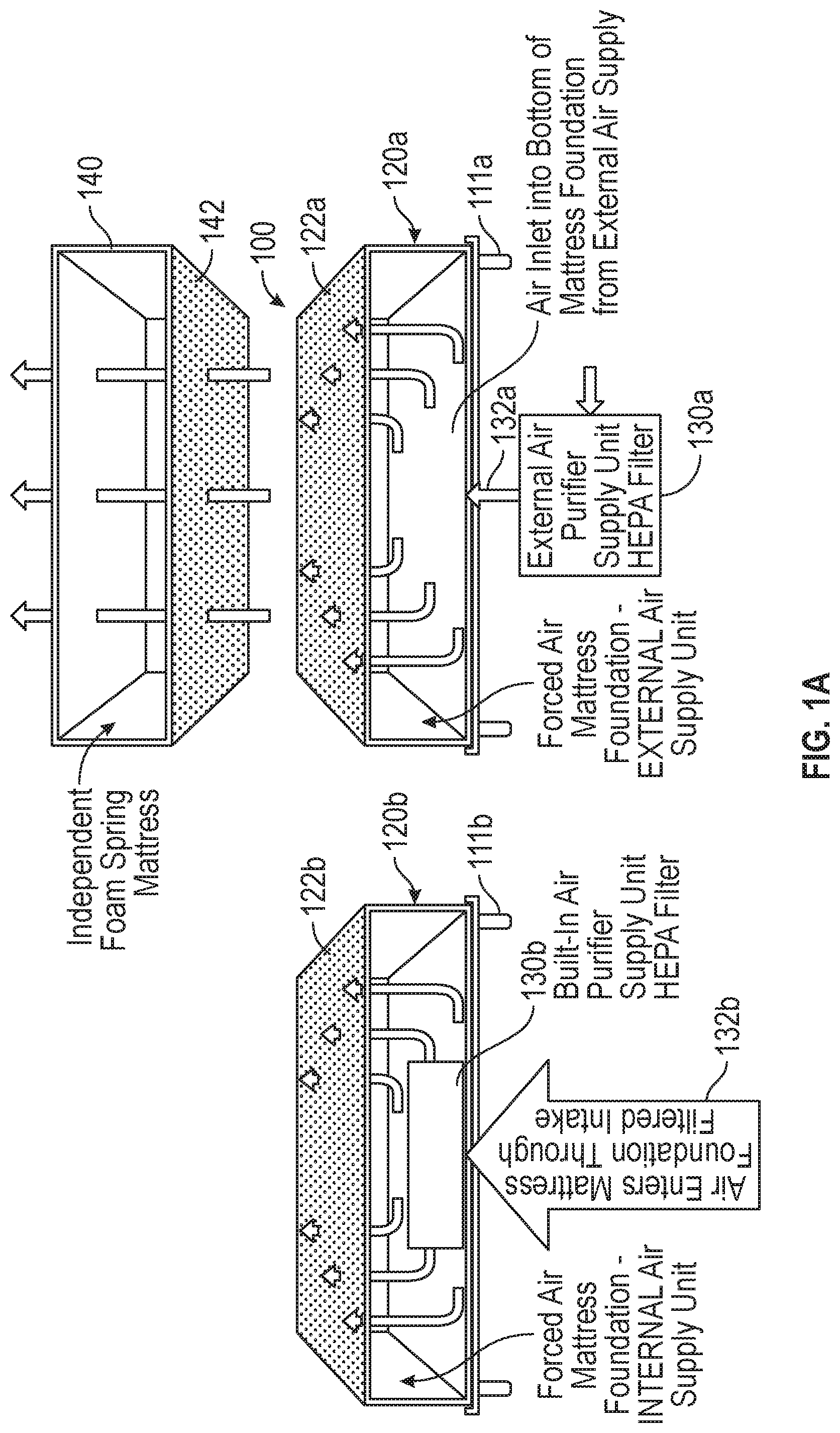
[0045] Turning now to the figures for specific exemplary embodiments, FIG. 1A illustrates exemplary embodiment(s) of a ventilated sleep system 100 (typically comprising a mattress and a foundation), with a ventilated mattress 140 used in conjunction with (typically directly atop) a ventilation foundation (such as either 120a or 120b, which basically differ regarding the location of the air flow unit 130a). The mattress 140 has a bottom surface 142 which allows airflow into and/or out of the mattress 140. For example, the bottom surface 142 of the mattress 140 cover might be formed of or comprise high airflow fabric, such as spacer fabric or mesh fabric (for example 150 gsm 100% polyester spacer mesh fabric and/or restricting airflow CFM less than about 35% at 3 PSI and/or a spacer fabric with a thickness of about 3.5 mm, a weight of about 245 g/m.sup.2, and/or an air permeability of about 636 ft3/ft2/minute at 0.018 PSI (e.g. per ASTM D737-96--Standard Test Method for Air Permeability of Textile Fabrics) and/or such high airflow mesh panels may be (inherently) fire resistant (FR--e.g. meeting US Federal Std. 1633)). In some embodiments, the high airflow fabric could be inherently FR, while in others, a spray-on or other FR treatment/additive might be used. In some embodiments, the upper surface 122a/b of the mattress 140 might also allow airflow into/out of the mattress 140 (for example, with the upper surface of the mattress 140 cover being formed of or comprising high airflow fabric, which could be similar to that used for the bottom surface 142 of the mattress cover as described above).
[0046] Either foundation 120a (with an air flow unit 130a external to the support structure of the foundation 120a and/or cover of the foundation 120a, for example externally mounted on the foundation, perhaps underneath the foundation 120a/b at or near the foot end of the bed, for example centered from side to side, and in fluid communication with the foundation 120a hollow cavity via inlet/intake/opening 132a) or 120b (with air flow unit 130b located within the foundation 120b support structure and/or cover, for example mounted internally on the bottom/base panel of the foundation 120b, perhaps within the foundation 120b at or near the foot end of the bed, for example on the left side when looking at the foundation 120b from the foot, and in fluid communication with the external environment via inlet/intake/opening 132b) might optionally be used with the mattress 140, with the mattress 140 being located atop either foundation 120a or 120b to form the ventilated sleep system 100. In both foundation embodiments 120a and 120b, the upper surface 122a or 122b, respectively, of the foundation 120a/b would be configured to allow airflow out of and/or into the foundation (for example, into a mattress 140 directly atop (and in contact with) the foundation. So for example, the upper surface 122a or 122b of the foundation cover might be formed of or comprise high airflow fabric, which could be spacer fabric or mesh fabric (similar to that described above with respect to the bottom surface 142 of the mattress cover, for example, to allow airflow communication between the foundation and the mattress 140, for example). And typically, the foundation might be held above the floor by a frame or legs 111a,b (which might be similar to conventional bed frames used for conventional box springs, for example, and which might provide sufficient clearance from the floor to allow the required airflow for operation of the ventilation mattress system). Typically, the frame would not interfere with or block the inlet/intake/opening 132a for the air flow unit 130a,b. As discussed above, some embodiments of the foundation might not include an airflow unit, especially if the ventilation foundation is used with a ventilation mattress (e.g. configured for billows effect).
[0047] So in FIG. 1A, air might pass into the foundation 120a,b, for example through a filter such as a HEPA filter and/or through a climate control unit (which might, for example, be operable to cool and/or heat the air) via an air flow unit 130a,b, passing through the foundation 120a/b (e.g. hollow cavity) to exit through the upper surface 122a,b of the foundation 120a/b and enter the bottom surface 142 of the mattress 140 in order to pass (vertically) through at least a portion of the mattress 140. In such a system, the air flow unit 130a,b might pump air into the mattress 140 through the foundation 120a/b. Alternatively, air might flow through the system in reverse, with the air flow unit 130a,b sucking air out of the mattress 140 and into the foundation 120a/b (and then out to the external environment). The air flow unit 130a,b typically might displace about 100-300 CFM, and typically might operate at less than about 6 dB. In some embodiments, the upper surface of the mattress 140 might also allow for airflow (for example, being formed of or comprising high airflow fabric or loosely woven fabric panels, similar to those previously described). In some embodiments, the high airflow fabric panels throughout the sleep system (or at least for the upper foundation cover surface and lower mattress cover surface) might all be similar and/or formed of the same material. In some embodiments, the air flow unit 130a,b might be configured to allow for forward and reverse operation (e.g. operable to allow air to be blown into or sucked out of the mattress by the foundation 120a/b). The arrows in FIG. 1A illustrate potential airflow in the system, as persons of skill would understand.
[0048] Typically, the foundation(s) 120a,b of FIG. 1A would comprise a hollow structure (formed for example by support struts and a structural frame), and air would be pumped into/out of the hollow structure cavity (for example by the air flow unit 130a,b). In other words, in such embodiments, air would simply flow through the hollow cavity of the foundation 120a/b as it interacts with the mattress 140 and the outside environment. So for example, external air might be drawn into the hollow cavity of the foundation 120a/b through the inlet/intake/opening 132a,b, flow through the hollow cavity to the upper surface of the foundation 120a,b, flow out of the foundation 120a/b through the upper surface 122a,b and into the mattress 140 through the mattress bottom surface 142, and then pass through at least a portion of the mattress 140 (and in some embodiments, air might flow all the way through the mattress 140 and optionally might flow out the upper surface of the mattress 140). Alternatively, air might flow into the hollow cavity of the foundation 120a,b through the upper surface 122a,b (for example, sucking air from the mattress 140 through the bottom surface 142 of the mattress 140), through the hollow cavity of the foundation 120, and out of the foundation 120 via inlet/intake (which in the case would actually serve as an outtake)/opening 132a,b to the external environment.
[0049] FIG. 1B illustrates an alternative embodiment sleep/bedding system, similar to that of FIG. 1A. One version of the foundation 120b of FIG. 1B may have an access panel, which for example might allow for easy access to change the HEPA filter and/or to provide maintenance or repair to the air flow unit 130b. FIGS. 1Ca, 1Cb and 1Cc illustrate in more detail an exemplary sleep/bedding system embodiment similar to FIG. 1B, having an internal (e.g. mounted/located within the foundation frame/cover) air flow unit 130b, with FIG. 1Ca showing a side view, FIG. 1Cb showing an end view of the foot of the bed, and FIG. 1Cc showing a top view. Typically, in the embodiment of FIGS. 1Ca, 1Cb and 1Cc the air flow unit 130b might be located at (e.g. in proximity to) the foot of the bed within the foundation. For example, the optional HEPA filter might be located over the air intake, with air then flowing through the blower to be expelled into the hollow cavity of the foundation 120b. In some embodiments, there may be an access panel, for example located on the upper surface of the foundation 120b above the HEPA filter or air intake or air flow unit 130b. The access panel might be a hinged section (for example, operable to open by pivoting upward) of the upper foundation 120b surface (although in some embodiments, the access panel portion of the upper foundation 120b cover might not be air permeable, for example to help direct air through the blower and into the foundation) 120b.
[0050] FIGS. 1Da, 1Db and 1Dc illustrate in more detail an exemplary sleep/bedding system embodiment similar to FIG. 1B, having an external (e.g. mounted/located outside the foundation 120b frame/cover, for example mounted beneath the foundation 120b) air flow unit 130a (shown in FIG. 1B), with FIG. 1Da showing a side view, FIG. 1Db showing an end view of the foot of the bed, and FIG. 1Dc showing a top view. Typically, the air flow unit 130a of FIGS. 1Da, 1Db and 1Dc might be mounted to the bottom surface of the foundation at or in proximity to the foot of the bed (perhaps located towards the center between the sides). And again, there may be an access panel, which for example might typically be located on the housing of the air flow unit to allow access to the HEPA filter and/or blower. FIG. 1E illustrates an exemplary sleep/bedding system in 3D perspective view, showing that externally the sleep/bedding system would resemble a conventional mattress atop a conventional box-spring foundation unit (e.g. a typical conventional bed).
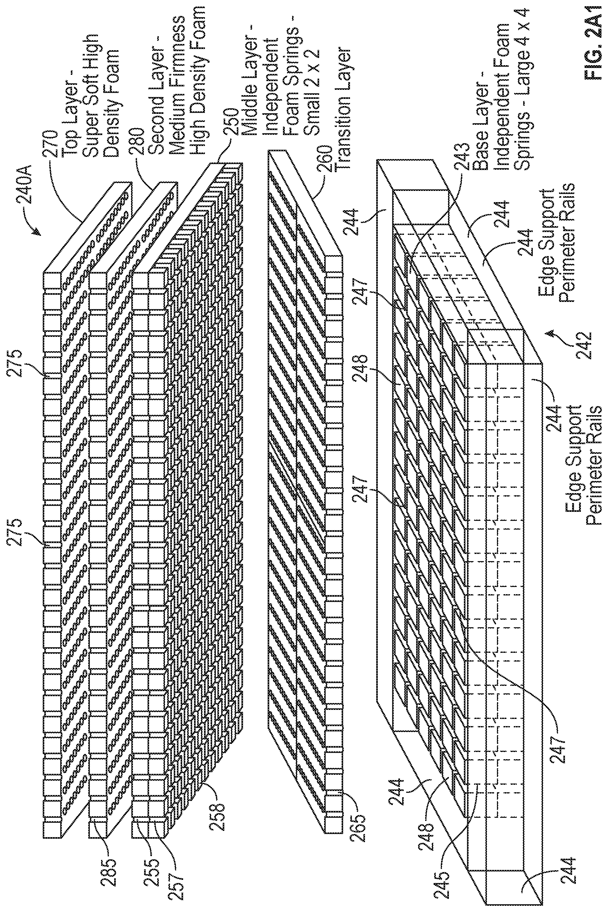
[0051] FIGS. 2A1 and 2A2 illustrate an exemplary ventilation mattress 240A, which is an all-foam (or spring-free) mattress formed of a plurality of foam layers 250 (with the base layer being a sculpted foam layer 250 having the sculpted surface (with foam pillars) facing upward, a middle sculpted foam layer 250 having the sculpted surface (with foam pillars) facing downward, a sleep surface layer, at least one foam layer (e.g. transition layer) between the middle sculpted foam layer 250 and the base sculpted foam layer, and/or a foam layer located between the sleep surface layer 270 and the middle sculpted foam layer 250). While FIG. 2A1 shows the foam components of the mattress (e.g. with the cover removed) in perspective view, FIG. 2A2 shows a side cross-section view of the same mattress. FIGS. 2B1 and 2B2 illustrate a similar all foam mattress (e.g. with the foam components removed from the cover), and differs primarily in the particular foam material selected (with the embodiment of FIG. 2A1 being formed of conventional high density foam (e.g. all component foam layers are formed of conventional high density foam), and the embodiment of FIG. 2B1 having the top two layers formed of memory foam, for example gel memory foam, while the remaining layers are formed of conventional high density foam). And in some embodiments, all such foam layers would be adhered into an integrated whole (e.g. laminated) and/or enclosed/encased in a cover, thereby forming an integrated mattress.
[0052] So in FIG. 2A1, the mattress 240A comprises a base layer of foam 242 (which comprises a sculpted foam element 243 with the sculpted surface (e.g. the foam pillars) facing/extending upward) located as the bottom layer of foam in the mattress 240A, a middle sculpted foam layer 250 with the sculpted surface (e.g. foam pillars) facing/projecting downward and located above the base layer (although typically not directly above or in contact with the base layer), a transition foam layer 260 located between (and typically in contact with) the base layer of sculpted foam 242 and the middle layer of sculpted foam 250, a top/sleep surface layer of foam 270 (typically located as the uppermost foam layer 250 in the mattress 240A), and (optionally) a second (e.g. penultimate) layer of foam 280 located between the sleep surface layer 270 and the middle sculpted foam layer 250. FIG. 2A1 shows the foam layers of the mattress 240A without the cover (not shown), illustrating the order and orientation of the foam layers in this mattress embodiment. Typically, the foam layers are arranged one atop another in the order described above, with proximate layers contacting one another (e.g. the base layer 242 is the bottom layer, the transition layer 260 is located atop and in contact with the base layer 242, the middle sculpted foam layer 250 is located atop and in contact with the transition layer, the second (penultimate) layer 280 is located atop and in contact with the middle sculpted foam layer 250, and the top (sleep surface) layer 270 is located atop and in contact with the second (penultimate) layer 280 and forms the upper foam layer of the mattress 240A). Typically, the layers would all be encased within a cover (not shown here), and typically the cover would have a bottom surface with means for airflow (for example, one or more panels of high airflow fabric, such as spacer fabric or mesh fabric). Also, in some embodiments, the upper surface of the cover might include means for airflow (for example, an air permeable element, such as one or more panels of high airflow fabric, such as spacer fabric or mesh fabric).
[0053] In FIG. 2A1, the base layer 242 comprises a sculpted foam element/layer 243 with upward facing sculpted surface (e.g. foam pillars 248 projecting upward and separated by a series (e.g. grid) of gaps or grooves or cuts 247), and edge perimeter rails of foam 244 which surround/encase the sculpted foam element 243 on all sides (e.g. about/around the perimeter of the sculpted foam element 243). Typically, the edge support perimeter rails 244 might be formed of the same foam as the base layer sculpted foam element 243 and/or might have the same uncompressed height as the sculpted foam element 243 (e.g. the upper surface of the edge support perimeter rails 244 might be approximately level with the upper surface of the foam pillars 248 of the sculpted foam element 243 when both are uncompressed). In the embodiment of FIG. 2A1, the foam pillars 248 would typically have a square rectangular outer surface (and/or cross-section) of about 4 inches by 4 inches, and the gaps/grooves 247 forming the grid resulting in the foam pillars 248 might typically have a width of about 0.75 inches and a depth of about 3 inches. So for example, the gaps/grooves 247 in the base layer 242 might typically have a depth ranging from about 1/2 to 2/3 the total height for the base layer 242, for example about 60% in some exemplary embodiments. In addition, the joined bases of the foam pillars 248 of the sculpted foam element 243 typically would have a plurality of pinholes (e.g. essentially vertical air passageways), as will be described in greater detail below. In alternate embodiments, the pinholes might pass through both the base portion and the pillar portion of one or more of the sculpted foam layers 250.
[0054] In FIG. 2A1, the transition layer of foam 260 would typically be a flat sheet of foam with a plurality of pinholes 265 (e.g. essentially vertical air passageways). In the embodiment of FIG. 2A1, the transition layer 260 would typically have the same width and length dimensions (e.g. depending on whether the mattress 240A is a twin, full/double, queen, king, etc.) as the base layer 242 (e.g. including both the sculpted foam element 243 and the surrounding edge support perimeter rails 244), although in other embodiments (in which the foam pillars 248 are lower than the surrounding edge support perimeter rails 244, for example by a height approximately equal to the thickness of the transition layer, the transition layer 260 might be sized to fit over just the sculpted foam element 243 of the base layer 242 (e.g. so that it would be located within the edge support perimeter rails 244 as well).
[0055] The middle sculpted foam layer 250 of FIG. 2A1 would typically be sized (e.g. width and length) approximately the same as the base layer 242 and/or the transition layer 260 (and typically the same as the layers atop it as well), and would be oriented with the sculpted surface (e.g. foam pillars 258) facing/projecting downward. In the embodiment of FIG. 2A1, the foam pillars 258 would typically have a square rectangular outer surface (and/or cross-section) of about 2 inches by 2 inches, and the gaps/grooves 257 forming the grid resulting in the foam pillars might typically have a width of about 0.375 inches and a depth of about 1.75 inches. So for example, the gaps/grooves 257 in the middle sculpted layer 250 might typically have a depth ranging from about 1/2 to 2/3 the total height for the middle sculpted layer, for example about 55-60% in some exemplary embodiments. In addition, the joined bases of the foam pillars 258 of the middle sculpted layer 250 typically would have a plurality of pinholes 255 (e.g. essentially vertical air passageways), as will be described in greater detail below. Typically, the pinholes 255 of the middle sculpted foam layer 250 would be spaced and/or oriented/located the same (identically) as the pinholes 265 in the transition foam layer 260 (and typically also the same as the layers located above it), with the pinholes 255 aligning vertically with the pinholes 265. And typically, at least some of the pinholes 255/265 would also align with the pinholes 245 in the base layer 242 (e.g. the sculpted foam element 243 of the base layer 242). For example, every other pinhole 255/265 might align with a pinhole 245 (and groove/gap 247) in the sculpted foam element of the base layer.
[0056] The second (penultimate) foam layer 280 and the upper (sleep surface) foam layer 270 would typically each be a flat sheet of foam with a plurality of pinholes 285, 275 respectively (e.g. essentially vertical air passageways). In the embodiment of FIG. 2A1, both the second (penultimate) foam layer 280 and the upper (sleep surface) foam layer 270 would typically have the same width and length dimensions (e.g. depending on whether the mattress 240A is a twin, full/double, queen, king, etc.) as the base layer 242, the transition layer 260, and/or the middle sculpted layer 250. And, the pinholes 285, 275 of the second (penultimate) foam layer 280 and the top (sleep surface) layer 270 respectively would typically be spaced and/or oriented/located the same (identically) as the pinholes 265 in the transition foam layer 260 and the pinholes 255 in the middle sculpted foam layer 250, with the pinholes 285, 275 aligning vertically with the pinholes 265, 255. Thus, the pinholes 265, 255, 285, and 275 of FIG. 2A1 would typically align to form continuous airflow pathways from the upper surface of the base layer 242 upward to the upper surface of the mattress 240A (although in other embodiments, only some of the pinholes might align). And typically, at least some of the pinholes 285/275 would also align with the pinholes 245 in the base layer 242 (e.g. the sculpted foam element 243 of the base layer 242). For example, every other pinhole 285/275 might align with a pinhole 245 (and groove/gap 247) in the sculpted foam element 243 of the base layer 242. In other embodiments, the pinholes 265, 255, 285, and 275 might all align with the pinholes 245 in the base layer 242 (e.g. the pinholes in all the layers could be spaced equally so they all align to form continuous air flow pathways from the bottom surface of the mattress to the upper surface of the mattress 240A).
[0057] Similarly, FIG. 2A2 shows a cross-section view of the foam elements 243 of the mattress 240A shown in FIG. 2A1. In this embodiment, the base layer 242 typically would have an uncompressed height of about 5 inches, the transition layer 260 typically would have an uncompressed height of about 1.25 inches, the middle sculpted foam layer 250 typically would have an uncompressed height of about 3 inches, the second (penultimate) foam layer 280 typically would have an uncompressed height of about 1.75 inches, and the top (sleep surface) layer 270 typically would have an uncompressed height of about 1.25 inches. In FIG. 2A2, the foam layers 250 would typically vary in firmness, from softest at the top to hardest/firmest at the bottom. For example, the top (sleep surface) layer 270 would typically be the softest layer of foam (for example, IFD of about 14), the second (penultimate) layer 280 would typically be somewhat firmer that the top layer (for example, IFD of about 20), the middle sculpted foam layer 250 would typically be somewhat firmer than the second (penultimate) layer 280 (for example, IFD of about 35), the transition layer 260 typically would be somewhat firmer than the middle sculpted layer (for example, IFD of about 45), while the base layer 242 might typically have the same firmness as the transition layer 260 (for example, IFD of about 45). In other embodiments, the base layer 242 might be somewhat firmer than the transition layer 260. Typically, the edge support perimeter rails 244 would have the same firmness (e.g. IFD) and/or be formed of the same foam as the sculpted foam element 243 of the base layer. In other embodiments, the firmness of the various layers may differ and/or may vary differently from the descriptions above. And in FIG. 2A2, the thickness (e.g. lateral width) of the edge support perimeter rails typically would be about 4 inches (or in other embodiments, about the same size as one of the foam pillar's 248 square rectangular outer surface (and/or cross-section) sides).
[0058] FIG. 2A2 also shows the alignment of the pinholes 265, 255 (and gap 257), 285, and 275, and the fact that every other pinhole 265, 255, 285, 275 aligns with a pinhole 245 (and gap 247) of the base layer 242 in this embodiment. The alignment of pinholes may allow continuous airflow upward from the bottom surface of the mattress 240A to the upper surface of the mattress 240A and/or downward from the upper surface of the mattress 240A to the bottom surface of the mattress 240A, as illustrated by the exemplary airflow arrows (except along the perimeter edges where the edge support perimeter rails 244 may not have pinholes, in some embodiments). In some embodiments, the pinholes may be hole punched into the foam sheets/layers, while in other embodiments the pinholes might be formed for example by molding of the foam sheets/layers). And in some embodiments, the gaps/grooves 247, 257 might be cut/scored into the foam to form the sculpted surface(s), while in other embodiments the gaps/grooves 247, 257 might be formed for example by molding (e.g. due to the shape of the foam mold forming the layer(s)). The upper surface of the top layer of foam 270 forms the sleep surface 272 (although typically there would be a cover, not shown here, lying atop/encasing the foam).
[0059] So in some embodiments, the mattress might comprise at least two sculpted foam layers (with each having a sculpted surface with a plurality of pillars) with a transition foam layer (and typically only one such transition foam layer) therebetween. The upper sculpted foam layer would typically be oriented with its sculpted surface facing downward (although in other embodiments, it could face upward and/or there might not be a foam (transition) layer between the two sculpted foam layers), while the lower/bottom sculpted foam layer (e.g. the base layer) would typically be oriented with its sculpted surface facing upward. And typically (although optionally), there would be one or more foam layers located above the uppermost sculpted foam layer (e.g. the middle sculpted foam layer), with these top foam layers having a softer IFD than that of the middle sculpted foam layer. A series of pinholes in the foam layers (perhaps in conjunction with the gaps/grooves forming the sculpted surface of the sculpted foam layers) would allow for airflow vertically throughout the mattress (or at least through a plurality of foam layers of the mattress). And typically, the foam layers would be enclosed/encased within a cover, which typically would have a bottom/lower surface which is air permeable (for example, formed of or comprising high airflow fabric (such as spacer fabric or mesh fabric), typically allowing airflow comparable to the upper/top surface of the ventilation foundation upon which such a mattress would typically operate). So as discussed above, the mattress embodiment would typically have a bottom cover surface allowing airflow therethrough (e.g. one or more panels restricting airflow cubic feet per minute less than about 35% at 3 PSI and/or allowing approximately 100-300 CFM flow therethrough when used with an airflow unit and/or a billows effect mattress), and the ventilation foundation (upon/atop which the mattress embodiment would typically be used) typically would also have an upper/top cover surface allowing airflow therethrough (for example, similar to the airflow allowed by the bottom surface of the cover of the mattress), such that the joint mattress-foundation sleep/bedding system embodiment typically would effectively allow airflow between the foundation and the mattress (for example, based on an airflow unit in or on the foundation).
[0060] FIGS. 2B1 and 2B2 show a similar foam mattress 240B formed of multiple layers of foam (typically within a cover (not shown)). The embodiment of FIGS. 2B1 and 2B2 is substantially the same in structure as the embodiment of FIGS. 2A1 and 2A2, primarily differing in the foam material used. For example, in FIG. 2B1, the top two layers might be memory foam (for example, gel memory foam). Persons of skill will understand that the foam materials and/or characteristics of the layers of foam for such exemplary mattresses may differ, for example being selected based on the specific needs of the particular mattress.
[0061] FIG. 3 illustrates an exemplary base foam layer 242 (similar to that of FIG. 2A1, for example), showing the sculpted surface (e.g. upper surface) of the sculpted foam element 243 (with foam pillars 248 separated by gaps/grooves 247 in a grid) and the edge support perimeter rails 244 in plan view (of the upper, sculpted surface). As noted above, the foam edge support perimeter rails 244 surround and abut all four sides of the sculpted foam element 243, and they each may typically have a width (e.g. lateral dimension) approximately equal to one of the sides of the square rectangular outer surface (and/or cross-section) of the foam pillars 248. Typically (as shown in FIG. 3), all of the foam pillars 248 would be equally sized (for example, they might all be equally sized with a square cross-section, as for example formed by a grid of grooves/gaps 247 in which the longitudinal grooves/gaps 247 are equally spaced, and the lateral gaps/grooves 247 are also equally spaced apart by the same amount as the longitudinal gaps, for example forming a grid that resembles a checkerboard). So for example in the embodiment of FIG. 3, the foam pillars 248 would typically have a square rectangular outer surface (and/or cross-section) of about 4 inches by 4 inches, and the gaps/grooves 247 forming the grid resulting in the foam pillars 248 might typically have a width of about 0.75 inches and a depth of about 3 inches.
[0062] FIG. 3 also shows the pinholes 245 in the base layer 242, which are typically located in the joined base portion of the foam pillars 248 of the base layer 242 so that they exit into the gaps/grooves 247 separating the foam pillars 248. In other words, the pinholes 245 typically do not pass through the projecting foam pillar 248 portion of the base layer 242 sculpted foam element 243, but rather pass only through the integral base portion of the sculpted foam element 243 (e.g. the bottom portion where the foam pillars are joined together into an integral whole) such that the pinholes 245 extend upward from the bottom of the base layer 242 to exit within the gaps/grooves 247 between the foam pillars 248. The pinholes 245 of FIG. 3 typically might have a diameter of about 0.5 inches (and typically would all be about the same size), and typically would be spaced apart approximately 3.937 inches. So for example, the pinholes 245 typically might be located within the gaps/grooves 247 at locations in proximity to the corners of each foam pillar 248 of the base layer 242 (e.g. at the grid groove intersections).
[0063] Similarly, FIG. 4 illustrates an exemplary middle sculpted surface layer 250 (similar to that of FIG. 2A1, for example), showing the sculpted surface (e.g. the bottom surface) (with foam pillars 258 separated by gaps/grooves 257 in a grid) in plan view (of the sculpted surface). Typically (as shown in FIG. 4), all of the foam pillars 258 would be equally sized (for example, they might all be equally sized with a square cross-section, as for example formed by a grid of grooves/gaps 257 in which the longitudinal grooves/gaps 257 are equally spaced, and the lateral gaps/grooves are also equally spaced apart by the same amount as the longitudinal gaps, for example forming a grid that resembles a checkerboard). So for example in the embodiment of FIG. 4, the foam pillars 258 would typically have a square rectangular outer surface (and/or cross-section) of about 2 inches by 2 inches, and the gaps/grooves 257 forming the grid resulting in the foam pillars 258 might typically have a width of about 0.375 inches and a depth of about 1.75 inches. While the embodiment of FIG. 2A1, for example, has the foam pillars 258 of the middle sculpted foam layer sized to be about 1/4 the size of the foam pillars 248 of the base layer (e.g. 2 inches by 2 inches versus 4 inches by 4 inches, such that each 4.times.4 pillar in the base layer of FIG. 2A1, for example, might have four 2.times.2 pillars in the middle sculpted layer located above it); in other embodiments, the ratio of the foam pillar sizing may vary (for example, the foam pillars 258 could be the same size as the foam pillars 248 in some embodiments, or the foam pillars 258 might be 1/2, 1/3, 1/8, or 1/16 the size of the foam pillars 248 in other embodiments). Typically, the sizing ratio would be such that at least some of the gaps/grooves 257 in the middle sculpted foam layer would align with at least some of the gaps/grooves 247 of the base layer (since that may be important to aid in alignment of pinholes in some embodiments, as well as perhaps providing consistent support and/or comfort characteristics).
[0064] FIG. 4 also shows the pinholes 255 in the middle sculpted layer 250, which are typically located in the joined base portion of the foam pillars 258 of the middle sculpted layer 250 so that they exit into the gaps/grooves 257 separating the foam pillars 258. In other words, the pinholes 255 typically do not pass through the projecting foam pillar 258 portion of the middle sculpted foam layer 250, but rather pass only through the integral base portion of the middle sculpted layer 250 (e.g. the bottom portion where the foam pillars 258 are joined together into an integral whole) such that the pinholes 255 extend downward from the top of the middle sculpted layer 250 to exit within the gaps/grooves 257 between the foam pillars 258. The pinholes 255 of FIG. 4 typically might have a diameter of about 0.25 inches (and typically would all be about the same size), and typically would be spaced apart approximately 1.9685 inches. So for example, the pinholes 255 typically might be located within the gaps/grooves 257 at locations in proximity to the corners of each foam pillar 258 in the middle sculpted layer 250 (e.g. at the grid groove intersections). As discussed above, the pinholes in the foam layers (of an exemplary mattress) above the middle sculpted layer 250 (as well as perhaps an underlying transition layer) typically would be sized and spaced (e.g. located) identical to those in the middle sculpted layer 250, in order to form continuous airflow pathways upward.
[0065] FIG. 5A illustrates an exemplary ventilation mattress 540, which is an all-foam (or spring-free) mattress formed of a plurality of foam layers (with the base layer being a sculpted foam layer having the sculpted surface (with foam pillars) facing upward, a middle sculpted foam layer having the sculpted surface (with foam pillars) facing downward, a sleep surface layer, at least one foam layer (e.g. transition layer) between the middle sculpted foam layer and the base sculpted foam layer, and/or a foam layer located between the sleep surface layer and the middle sculpted foam layer). FIG. 5B illustrates a similar all foam mattress (e.g. with the foam components removed from the cover), and differs primarily in the middle layer construction. In some embodiments, all such foam layers would be adhered into an integrated whole (e.g. laminated) and/or enclosed/encased in a cover, thereby forming an integrated mattress.
[0066] So in FIG. 5A, the mattress 540 comprises a base layer of foam 242 (which comprises a sculpted foam element with the sculpted surface (e.g. the foam pillars) facing/extending upward) located as the bottom layer of foam in the mattress 540 (wherein the base layer 242 may be similar to the base layer 242 described above), a middle sculpted foam layer 550 with the sculpted surface (e.g. foam pillars) facing/projecting downward and located above the base layer 242 (although typically not directly above or in contact with the base layer 242), a transition foam layer 260 located between (and typically in contact with) the base layer of sculpted foam 242 and the middle layer of sculpted foam 550 (wherein the transition foam layer 260 may be similar to the transition foam layer 260 described above), a top/sleep surface layer of foam 270 (typically located as the uppermost foam layer in the mattress, wherein the top surface layer 270 may be similar to the top surface layer 270 described above), and (optionally) a second (e.g. penultimate) layer of foam 280 located between the sleep surface layer 270 and the middle sculpted foam layer 550 (wherein the second layer of foam 280 may be similar to the second layer of foam 280 described above).
[0067] FIG. 5A shows the foam layers of the mattress 540 without the cover (not shown), illustrating the order and orientation of the foam layers 550 in this mattress embodiment. Typically, the foam layers 550 are arranged one atop another in the order described above, with proximate layers contacting one another (e.g. the base layer 242 is the bottom layer, the transition layer 260 is located atop and in contact with the base layer, the middle sculpted foam layer 550 is located atop and in contact with the transition layer 260, the second (penultimate) layer 280 is located atop and in contact with the middle sculpted foam layer 550, and the top (sleep surface) layer 270 is located atop and in contact with the second (penultimate) layer 280 and forms the upper foam layer of the mattress 540). Typically, the layers would all be encased within a cover (not shown here), and typically the cover would have a bottom surface with means for airflow (for example, one or more panels of high airflow fabric, such as spacer fabric or mesh fabric. Also, in some embodiments, the upper surface of the cover might include means for airflow (for example, an air permeable element, such as one or more panels of high airflow fabric).
[0068] In FIG. 5A, the base layer 242 comprises a sculpted foam element/layer 243 with upward facing sculpted surface (e.g. foam pillars 248 projecting upward and separated by a series (e.g. grid) of gaps or grooves or cuts 247), and edge perimeter rails of foam 244 which surround/encase the sculpted foam element 243 on all sides (e.g. about/around the perimeter of the sculpted foam element 243). Typically, the edge support perimeter rails 244 might be formed of the same foam as the base layer sculpted foam element 243 and/or might have the same uncompressed height as the sculpted foam element 243 (e.g. the upper surface of the edge support perimeter rails 244 might be approximately level with the upper surface of the foam pillars 248 of the sculpted foam element 243 when both are uncompressed).
[0069] In the embodiment of FIG. 5A, the foam pillars 248 would typically have a square rectangular outer surface (and/or cross-section) of about 4 inches by 4 inches, and the gaps/grooves 247 forming the grid resulting in the foam pillars might typically have a width of about 0.75 inches and a depth of about 3 inches. So for example, the gaps/grooves 247 in the base layer might typically have a depth ranging from about 1/2 to 2/3 the total height for the base layer, for example about 60% in some exemplary embodiments. In addition, the joined bases of the foam pillars of the sculpted foam element 243 typically would have a plurality of pinholes 265 (e.g. essentially vertical air passageways), as will be described in greater detail below. In alternate embodiments, the pinholes might pass through both the base portion and the pillar portion of one or more of the sculpted foam layers 550.
[0070] In FIG. 5A, the transition layer of foam 260 would typically be a flat sheet of foam with a plurality of pinholes 265 (e.g. essentially vertical air passageways). In the embodiment of FIG. 5A, the transition layer 260 would typically have the same width and length dimensions (e.g. depending on whether the mattress is a twin, full/double, queen, king, etc.) as the base layer 242 (e.g. including both the sculpted foam element 243 and the surrounding edge support perimeter rails 244), although in other embodiments (in which the foam pillars are lower than the surrounding edge support perimeter rails, for example by a height approximately equal to the thickness of the transition layer, the transition layer 260 might be sized to fit over just the sculpted foam element 243 of the base layer 242 (e.g. so that it would be located within the edge support perimeter rails 244 as well).
[0071] The middle sculpted foam layer 550 of FIG. 5A would typically be sized (e.g. width and length) approximately the same as the base layer 242 and/or the transition layer 260 (and typically the same as the layers atop it as well), and would be oriented with the sculpted surface (e.g. foam pillars 554) facing/projecting downward. In the embodiment of FIG. 5A, the foam pillars 554 would typically have a square/rectangular outer surface (and/or cross-section) of about 4 inches by 4 inches, and the gaps/grooves 557 forming the grid resulting in the foam pillars might typically have a width of about 0.375 inches and a depth of about 1.75 inches. So for example, the gaps/grooves 557 in the middle sculpted layer 550 might typically have a depth ranging from about 1/2 to 2/3 the total height for the middle sculpted layer 550, for example about 55-60% in some exemplary embodiments. In addition, the joined bases of the foam pillars of the middle sculpted layer 550 typically would have a plurality of pinholes 555 (e.g. essentially vertical air passageways), as will be described in greater detail below.
[0072] In the embodiment shown in FIG. 5A, the pinholes 555 of the middle sculpted foam layer 550 may be spaced and/or oriented/located the same (identically) as the pinholes 245 of the base layer 242. And typically, at least some of the pinholes 555 may align with the pinholes 265 in the transition foam layer 260 (as well as the layers located above it), with some of the pinholes 265 aligning with the pinholes 555. For example, every other pinhole 265 might align with a pinhole 555 in the middle sculpted foam layer 550.
[0073] The middle layer 550 may also comprise an additional set of pillars 552 located on the top surface of the middle layer 550. In the embodiment of FIG. 5A, the top pillars 552 may be sized differently than the bottom pillars 554 (for example, the top pillar 552 might be 1/4 the (cross-section) size of the bottom pillars 554, with four top pillars 552 for each corresponding bottom pillar, although in other embodiments the top and bottom pillars 552/554 could be the same size). In the embodiment of FIG. 5A, the pinholes 555 may align with every groove 557 in the bottom pillars 554, while the pinholes 555 may align with every other groove 553 in the top pillars 552. In some embodiments, the grooves 553 of the top pillars 552 may align with the pinholes 275, 285 of the top (sleep surface) layer 270 and second layer 280.
[0074] The second (penultimate) foam layer 280 and the upper (sleep surface) foam layer 270 would typically each be a flat sheet of foam with a plurality of pinholes 285, 275 respectively (e.g. essentially vertical air passageways). In the embodiment of FIG. 5A, both the second (penultimate) foam layer 280 and the upper (sleep surface) foam layer 270 would typically have the same width and length dimensions (e.g. depending on whether the mattress is a twin, full/double, queen, king, etc.) as the base layer 242, the transition layer 260, and/or the middle sculpted layer 550. And, the pinholes 285, 275 of the second (penultimate) foam layer 280 and the top (sleep surface) layer 270 respectively would typically be spaced and/or oriented/located the same (identically) as the pinholes 265 in the transition foam layer 260 and optionally the pinholes 555 in the middle sculpted foam layer 550, with the pinholes 285, 275 aligning vertically with the pinholes 265, 555. Thus, the pinholes 265, 555, 285, and 275 of FIG. 5A would typically align to form continuous airflow pathways from the upper surface of the base layer 242 upward to the upper surface of the mattress (although in other embodiments, only some of the pinholes might align). And typically, at least some of the pinholes 285/275 would also align with the pinholes 245 in the base layer 242 (e.g. the sculpted foam element 243 of the base layer). For example, every other pinhole 285, 275 might align with a pinhole 245 (and groove/gap 247) in the sculpted foam element 243 of the base layer 242. In other embodiments, the pinholes 265, 555, 285, and 275 might all align with the pinholes 245 in the base layer 242 (e.g. the pinholes in all the layers could be spaced equally so they all align to form continuous air flow pathways from the bottom surface of the mattress to the upper surface of the mattress).
[0075] In FIG. 5A, the foam layers would typically vary in firmness, from softest at the top to hardest/firmest at the bottom. For example, the top (sleep surface) layer 270 would typically be the softest layer of foam (for example, IFD of about 14), the second (penultimate) layer 280 would typically be somewhat firmer than the top layer (for example, IFD of about 20), the middle sculpted foam layer 550 would typically be somewhat firmer than the second (penultimate) layer 280 (for example, IFD of about 35), the transition layer 260 typically would be somewhat firmer than the middle sculpted layer 550 (for example, IFD of about 45), while the base layer 242 might typically have the same firmness as the transition layer 260 (for example, IFD of about 45). In other embodiments, the base layer 242 might be somewhat firmer than the transition layer 260. Typically, the edge support perimeter rails 244 would have the same firmness (e.g. IFD) and/or be formed of the same foam as the sculpted foam element 243 of the base layer 242. In other embodiments, the firmness of the various layers may differ and/or may vary differently from the descriptions above. In some embodiments, the thickness (e.g. lateral width) of the edge support perimeter rails 244 typically would be about 4 inches (or in other embodiments, about the same size as one foam pillar 248 square rectangular outer surface (and/or cross-section) sides).
[0076] The alignment of pinholes may allow continuous airflow upward from the bottom surface of the mattress to the upper surface of the mattress 540 and/or downward from the upper surface of the mattress to the bottom surface of the mattress 540 (except along the perimeter edges where the edge support perimeter rails may not have pinholes, in some embodiments). In some embodiments, the pinholes may be hole punched into the foam sheets/layers, while in other embodiments the pinholes might be formed for example by molding of the foam sheets/layers).
[0077] So in some embodiments, the mattress might comprise at least two sculpted foam layers (with each having a sculpted surface with a plurality of pillars) with a transition foam layer (and typically only one such transition foam layer) therebetween. The upper sculpted foam layer would typically be oriented with its sculpted surface facing downward (although in other embodiments, it could face upward and/or there might not be a foam (transition) layer between the two sculpted foam layers and/or the upper sculpted foam layer might have both an upper and lower sculpted surface), while the lower/bottom sculpted foam layer (e.g. the base layer) would typically be oriented with its sculpted surface facing upward. And typically (although optionally), there would be one or more foam layers located above the uppermost sculpted foam layer (e.g. the middle sculpted foam layer), with these top foam layers having a softer IFD than that of the middle sculpted foam layer. A series of pinholes in the foam layers (perhaps in conjunction with the gaps/grooves forming the sculpted surface of the sculpted foam layers) would allow for airflow vertically throughout the mattress (or at least through a plurality of foam layers of the mattress). And typically, the foam layers would be enclosed/encased within a cover, which typically would have a bottom/lower surface which is air permeable (for example, formed of or comprising high airflow fabric (such as spacer fabric or mesh fabric), typically allowing airflow comparable to the upper/top surface of the ventilation foundation upon which such a mattress would typically operate). So as discussed above, the mattress embodiment would typically have a bottom cover surface allowing airflow therethrough (e.g. one or more panels restricting airflow per cubic feet per minute less than about 35% at 3 PSI), and the ventilation foundation (upon/atop which the mattress embodiment would typically be used) typically would also have an upper/top cover surface allowing airflow therethrough (for example, similar to the airflow allowed by the bottom surface of the cover of the mattress), such that the joint mattress-foundation sleep/bedding system embodiment typically would effectively allow airflow between the foundation and the mattress (for example, based on an airflow unit in or on the foundation).
[0078] FIG. 5B shows a similar foam mattress 542 formed of multiple layers of foam (typically within a cover (not shown). The embodiment of FIG. 5B is substantially the same in structure as the embodiment of FIG. 5A, primarily differing in the construction of the middle layer 560. In the embodiment of FIG. 5B the middle sculpted foam layer 560 would typically be sized (e.g. width and length) approximately the same as the base layer 242 and/or the transition layer 260 (and typically the same as the layers atop it as well), and would be oriented with the sculpted surface (e.g. foam pillars 556) facing/projecting downward. In the embodiment of FIG. 5B, the foam pillars 556 would typically have a square rectangular outer surface (and/or cross-section) of about 2 inches by 2 inches, and the gaps/grooves 557 forming the grid resulting in the foam pillars might typically have a width of about 0.375 inches and a depth of about 1.75 inches. So for example, the gaps/grooves in the middle sculpted layer might typically have a depth ranging from about 1/2 to 2/3 the total height for the middle sculpted layer, for example about 55-60% in some exemplary embodiments. In addition, the joined bases of the foam pillars of the middle sculpted layer 560 typically would have a plurality of pinholes 555 (e.g. essentially vertical air passageways), as will be described in greater detail below. Typically, the pinholes 555 of the middle sculpted foam layer 560 would be spaced and/or oriented/located the same (identically) as the pinholes 265 in the transition foam layer 260 (and typically also the same as the layers located above it), with the pinholes 555 aligning vertically with the pinholes 265. And typically, at least some of the pinholes 555/265 would also align with pinholes in the base layer 242 (e.g. the sculpted foam element 243 of the base layer). For example, every other pinhole 555, 265 might align with a pinhole (and groove/gap 247) in the sculpted foam element 243 of the base layer 242.
[0079] The middle layer 560 may also comprise an additional set of pillars 552 located on the top surface of the middle layer 560. In the embodiment of FIG. 5A, the top pillars 552 may be sized the same (identical) as the bottom pillars 554. In the embodiment of FIG. 5A, the pinholes 555 may align with every groove 557 in the bottom pillars 554, and the pinholes 555 may align with every groove 553 in the top pillars 552.
[0080] FIGS. 6A-6B illustrate detailed views of the middle sculpted foam layers 550 and 560. The middle sculpted foam layer 550 of FIG. 6A may comprise top pillars 552 and bottom pillars 554 that differ in size. For example, the top pillars 552 may typically have a square rectangular outer surface (and/or cross-section) of about 2 inches by 2 inches, while the bottom pillars 554 may typically have a square rectangular outer surface (and/or cross-section) of about 4 inches by 4 inches. The middle sculpted foam layer 560 of FIG. 6B may comprise top pillars 552 and bottom pillars 554 that are the same in size. For example, the top pillars 552 may typically have a square rectangular outer surface (and/or cross-section) of about 2 inches by 2 inches, and the bottom pillars 556 may also typically have a square rectangular outer surface (and/or cross-section) of about 2 inches by 2 inches. Typically, the foam pillars of the middle sculpted foam layer would be sized with respect to the pillars of the base layer of foam within a range including 1-to-1-4-to-1 with respect to cross-section (such that the foam pillars of the middle sculpted foam layer each range in size from being equally sized to the base layer pillars down to being a quarter the size of the base layer pillars (i.e. four middle sculpted layer pillars per one base layer pillar)), with each top foam pillar of the middle sculpted foam layer often being equally sized and each bottom foam pillar of the middle sculpted foam layer often being equally sized. So for example, the base layer foam pillars might be 4.times.4 inches in cross-section, and the middle sculpted foam layer might have pillars that are 4.times.4 inches or 2.times.2 inches (for example, the bottom pillars of the middle sculpted foam layer could be 4.times.4 inches or 2.times.2 inches, while the top pillars of the middle sculpted foam layer could be 2.times.2 inches (or 4.times.4 inches)).
[0081] Additionally, the pinholes 555 in the middle sculpted layers 550 and 560 may align with the grooves 557 in the bottom pillars 554/556 in both embodiments. Therefore, the pinholes 555 of the middle sculpted layer 550 of FIG. 6A may be fewer in number and spaced differently than the pinholes 555 of the middle sculpted layer 560 of FIG. 6B.
[0082] In the embodiment shown in FIG. 6A, the middle sculpted foam layer 550 may be formed of one piece of foam, wherein the pillars 552/554 and pinholes 555 may be formed by sculpting and/or molding a single piece of foam. In the embodiment shown in FIG. 6B, the middle sculpted foam layer 560 may be formed of one piece of foam, wherein the pillars 552/556 and pinholes 555 may be formed by sculpting and/or molding a single piece of foam.
[0083] FIGS. 7A-7B illustrate alternative detailed views of the middle sculpted foam layers 550 and 560. In FIGS. 7A-7B, the middle layers 550 and 560 may comprise two different types of foam joined together using adhesive. The middle layers 550 and 560 may be similar to those described in FIGS. 6A-6B, except that the layers may be formed of two pieces of foam instead of one.
[0084] In the embodiment shown in FIG. 7A, the middle sculpted foam layer 550 may be formed of two pieces of foam, wherein the pillars 552 and partial pinholes 555 may be formed by sculpting and/or molding a first piece of foam 720, and the pillars 554 and partial pinholes 555 may be formed by sculpting and/or molding a second piece of foam 722. Then, the two pieces of foam 720 and 722 may be joined together and laminated to form the middle sculpted foam layer 550.
[0085] In the embodiment shown in FIG. 7B, the middle sculpted foam layer 560 may be formed of two pieces of foam, wherein the pillars 552 and partial pinholes 555 may be formed by sculpting and/or molding a first piece of foam 720, and the pillars 556 and partial pinholes 555 may be formed by sculpting and/or molding a second piece of foam 724. Then, the two pieces of foam 720 and 724 may be joined together and laminated to form the middle sculpted foam layer 560.
[0086] FIG. 8 illustrates an exemplary base foam layer 242 similar to that shown and described in FIG. 3.
[0087] FIG. 9 illustrates a ventilation/breathable sleep system 900 (e.g. with ventilation mattress 910 (preferably configured for billows effect) atop a ventilation/breathable (airflow) foundation 920). This sleep system embodiment allows airflow (e.g. fluid communication) between the mattress 910 and the foundation 920 (which may be one way or two way air flow, depending on the specific configuration and/or operation) via the interface of the upper surface (e.g. with high airflow fabric, such as spacer fabric or mesh fabric 922) of the foundation 920 and the lower surface (e.g. with high airflow fabric, such as spacer fabric or mesh fabric 912) of the mattress 910 (and typically, the same type and/or amount of high airflow fabric would be used for both the upper surface of the foundation and the lower surface of the mattress). The ventilation/breathable (e.g. airflow) mattress foundation 920 of FIG. 9 is configured to allow for air to pass through the foundation, for example from the external environment to a ventilation mattress 910 located on the upper surface of the foundation 920 through a high airflow fabric on the upper surface (e.g. air might flow through the lower surface of the foundation (which typically comprises high airflow fabric) from the external environment, through the hollow cavity of the foundation (e.g. within the frame structural support of the foundation and the enclosing cover), and through the upper surface of the foundation) and/or from such a ventilation mattress to the external environment through a high airflow fabric on the upper surface of the foundation (e.g. air might flow from the mattress into the foundation through the upper surface of the foundation, through the hollow cavity of the foundation (e.g. within the frame structural support of the foundation and the enclosing cover), and through the lower surface of the foundation, which typically comprises high airflow fabric, into the external environment).
[0088] Typically, the foundation embodiment of FIG. 9 would include a support structure and a foundation cover, located on and typically encompassing/enclosing the support structure to form a hollow cavity inside the foundation (which would be substantially open in FIG. 9, for example with no interior elements that might block airflow except for optionally one or more internal support beams--although in other embodiments, there could be internal structure so long as it does not substantially interfere with airflow through the foundation) (and in FIG. 9, there would be no airflow unit for forced air). Typically, the upper surface of the support structure of the foundation would include a plurality of slats (spaced apart, but providing ample support for a mattress), which would typically comprise wood slats. In some embodiments, there may be one or two support beams for the support structure of the foundation as well (e.g. on the upper surface of the foundation). The foundation cover would include an upper surface (configured for the mattress to rest atop and/or to be located atop/above the upper surface of the foundation support structure) having one or more means for airflow (e.g. air permeable element, such as high airflow fabric, such as spacer fabric or mesh fabric (for example 150 gsm 100% polyester spacer mesh fabric restricting airflow CFM less than about 35% at 3 PSI and/or spacer fabric with a thickness of about 3.5 mm, a weight of about 245 g/m.sup.2, and/or an air permeability of about 636 ft3/ft2/minute at 0.018 PSI and/or such high airflow panels may be (inherently) fire resistant (FR--e.g. meeting US Federal Std. 1633). In the embodiment shown in FIG. 9, the foundation cover also has a lower surface (e.g. directed towards the ground/floor) which also has a similar means for airflow/air permeable element/high airflow fabric. For example, the lower surface might comprise polyester non-woven fabric (as an air permeable dust protector) with a thickness of about 0.004 mm and/or a weight of about 1.5 oz./ft.sup.2. In the embodiment of FIG. 9, (substantially/approximately) the entire upper and lower surface of the foundation cover would be formed of high airflow fabric (for example 150 gsm 100% polyester spacer mesh fabric restricting airflow CFM less than about 35% at 3 PSI and/or spacer fabric with a thickness of about 3.5 mm, a weight of about 245 g/m.sup.2, and/or an air permeability of about 636 ft3/ft2/minute at 0.018 PSI and/or such high airflow mesh fabric may be (inherently) fire resistant (FR--e.g. meeting US Federal Std. 1633)). In some embodiments, the high airflow fabric could also be fire resistant, for example inherently FR and/or made FR by a FR additive (e.g. chemically treated with FR solution) and/or able to meet or exceed U.S. Federal Std. 1633. In other embodiments, the foundation and/or sleep system may meet or exceed the 1633 burn test requirements even when using non-FR cover materials and/or substrate materials.
[0089] In FIG. 9, the foundation might also include a substrate underlying the upper surface of the foundation cover, for example located between and typically in contact with the upper surface portion of the foundation cover and the upper surface (e.g. slats) of the foundation support structure. Typically, such substrate would span (substantially/approximately) the entire upper surface of the foundation support structure (e.g. underlie substantially/approximately the entire upper surface of the foundation cover) and would be firm enough to prevent the cover (upper surface) from sinking between the slats of the upper surface of the support structure/frame. Additionally, the substrate would typically be sufficiently breathable to not restrict airflow any more than the upper surface and/or lower surface of the foundation cover and/or the billows effect produced by the mattress and/or could provide air permeability from 140-250 ft3/ft2/minute at 0.018 PSI (per ASTM D737-96 Standard) and/or about 212 ft3/ft2/minute at 0.018 PSI. The breathability/permeability could either be due to use of a sufficiently air permeable material for the substrate, perforations providing the required breathability, and/or combinations thereof In some embodiments, the substrate would also be fire resistant, for example meeting or exceeding U.S. Federal Standard 1633. So typically, the entire foundation and/or sleep system should be able to meet or exceed U.S. Federal Std. 1633. In some embodiments, the substrate might comprise a fiber pad and/or a nylon webbing. In some exemplary embodiments, the substrate might be polyester non-woven fabric with a thickness of about 0.05 mm, a weight of about 4.8 oz./ft.sup.2, and/or an air permeability of about 212 ft3/ft2/minute (e.g. at 0.018 PSI and/or per ASTM D737-96 Standard). The overall/composite air permeability of the foundation (e.g. accounting for both the upper and lower surfaces of the cover and the substrate) might typically be at least 100 ft3/ft2/minute (e.g. at 0.018 PSI and/or per ASTM D737-96 Standard), at least 125 ft3/ft2/minute (e.g. at 0.018 PSI and/or per ASTM D737-96 Standard), at least 140 ft3/ft2/minute (e.g. at 0.018 PSI and/or per ASTM D737-96 Standard), about 142 ft3/ft2/minute (e.g. at 0.018 PSI and/or per ASTM D737-96 Standard), 140-212 ft3/ft2/minute (e.g. at 0.018 PSI and/or per ASTM D737-96 Standard), 140-636 ft3/ft2/minute (e.g. at 0.018 PSI and/or per ASTM D737-96 Standard), 125-212 ft3/ft2/minute (e.g. at 0.018 PSI and/or per ASTM D737-96 Standard), or 100-212 ft3/ft2/minute (e.g. at 0.018 PSI and/or per ASTM D737-96 Standard), by way of example.
[0090] Prior conventional foundations had low to no airflow capabilities, in part due to the materials previously used to meet the FR standards and/or in part due to the lack of focus regarding breathability of the mattresses (e.g. since high airflow mattresses and/or mattresses with billows effect were not previously a particular concern). Disclosed embodiments may address the FR issue by using an upper surface cover material for the foundation (and/or substrate) that is fire resistant and/or by using a foundation design/construction that overcomes/addresses the FR requirements without the need for FR materials. While such fire resistance could come from treatments (e.g. topical application of FR chemicals, for example with a spray-on FR additive and/or simply due to design/construction), in FIG. 9 the upper surface of the foundation cover (e.g. the one or more high airflow panels) may be formed of or comprise inherently FR high airflow fabric (although other embodiments may use cover material that is not FR, which may still render the entire foundation or sleep system sufficiently FR). In some embodiments, the lower surface of the foundation cover could also comprise the same type of high airflow fabric material (although in other embodiments, a breathable dust cover material, such as polyester non-woven fabric with a thickness of about 0.004 mm and/or a weight of about 1.5 oz./ft.sup.2, might be sufficient).
[0091] One illustrative example of an exemplary breathable foundation embodiment might include the following specifics, merely as a non-exclusive example: An upper surface of the cover comprising spacer fabric (on top of foundation and just above the Polyester Non-Woven Fabric substrate) with a thickness of about 3.5 mm, a weight of about 245 g/m.sup.2, and/or air permeability of about 636 ft3/ft2/minute at 0.018 PSI (e.g. per ASTM D737-96--Standard Test Method for Air Permeability of Textile Fabrics); Polyester Non-Woven Fabric substrate (e.g. underneath the Spacer Fabric and on top of wooden slats of the support/frame) with a thickness of about 0.05 mm, a weight of about 4.8 oz./ft.sup.2, and/or an air permeability of about 212 ft3/ft2/minute (e.g. at 0.018 PSI and/or per ASTM D737-96--Standard Test Method for Air Permeability of Textile Fabrics); and a Polyester Non-Woven Fabric lower surface of the cover (e.g. as an underneath foundation breathable dust protector) with a thickness of about 0.004 mm and/or a weight of about 1.5 oz./ft.sup.2. Such an exemplary foundation might have a composite air permeability of about 142 ft3/ft2/minute (e.g. at 0.018 PSI and/or per ASTM D737-96--Standard Test Method for Air Permeability of Textile Fabrics). Stated another way, the composite air permeability of such a breathable foundation might be about 142 ft3/ft2/minute (e.g. at 0.018 PSI and/or per ASTM D737-96--Standard Test Method for Air Permeability of Textile Fabrics) greater than a standard, conventional mattress foundation.
[0092] In FIG. 9, a ventilation mattress 910 may be used atop the ventilation (e.g. airflow) foundation 920, to form a ventilation sleep system 900. The ventilation mattress would typically have a mattress cover (encompassing/enclosing the support/cushioning elements of the mattress) with a lower surface (configured to rest atop the foundation and to be located in proximity to and/or contact the upper surface of the foundation), and the lower surface of such ventilation mattress would typically include one or more means for airflow (e.g. air permeable element, such as high airflow fabric, such as spacer fabric or mesh fabric 912 (for example 150 gsm 100% polyester spacer mesh fabric restricting airflow CFM less than about 35% at 3 PSI and/or a spacer fabric with a thickness of about 3.5 mm, a weight of about 245 g/m.sup.2, and/or an air permeability of about 636 ft3/ft2/minute at 0.018 PSI (e.g. per ASTM D737-96--Standard Test Method for Air Permeability of Textile Fabrics) and/or such high airflow mesh fabric may be (inherently) fire resistant (FR--e.g. meeting US Federal Std. 1633))), for example similar to a spacer fabric or mesh fabric 922 of the upper surface of the corresponding ventilation foundation 920 and, in some embodiments, of the lower surface of the ventilation foundation 920. In some embodiments, the ventilation foundation 920 also includes an air-permeable non-woven fabric 924, for example, disposed beneath the spacer fabric or mesh fabric 922 of the upper surface of the ventilation foundation. In some embodiments, (substantially/approximately) the entire lower surface of the mattress cover would be formed of the high airflow fabric (e.g. three-dimensional/spacer fabric) and/or the amount (e.g. surface area) and/or location of such high airflow fabric panel(s) would correspond/match (e.g. be approximately the same as) that of the corresponding foundation (on which the mattress would lay atop). In some embodiments, the mattress cover's upper surface would be similar to that of the lower surface of the mattress cover (e.g. with respect to airflow and/or materials)--although in other embodiments, it could differ (for example, providing less airflow and/or loft). Additionally, in some embodiments the
[0093] In some embodiments, the ventilation mattress would also be configured to provide a billows effect, which (with body movement of a user atop the ventilation mattress) might move air between the foundation and mattress of the ventilation sleep system. For example, the mattress support-comfort elements (e.g. within the mattress cover) might include one or more foam layers with vertical ventilation passageways therethrough and/or one or more foam layers having a sculpted surface of foam pillars (for example, as described above with respect to FIG. 2A1-FIG. 8). In some embodiments, the foam pillars of the sculpted surface would cover substantially/approximately one entire surface of a foam layer (e.g. a top and/or bottom surface of one or more foam layers, which might for example substantially span the mattress). In FIG. 9, two foam layers may be present as having sculpted surfaces with foam pillars, for example with the base layer having the sculpted surface facing upward and the other sculpted layer having its sculpted surface facing downward (for example, with two foam pillars of the upper sculpted layer spanning a side of a single foam pillar of the base layer, which could mean 2 or 4 smaller pillars per larger base pillar for example). Some embodiments could also include one or more horizontal ventilation passageways (which in some embodiments might be formed by the gaps/grooves forming the grid of foam pillars of the sculpted surface of one or more foam layers and/or could be channels formed in a surface of a foam layer). Typically, the vertical ventilation passageways and/or the horizontal ventilation passageways would be in fluid communication with the lower surface of the mattress cover (such that the billows effect would circulate air into and/or out of the mattress through the lower surface of the mattress cover) and/or with each other (such that the billows effect might use the entire ventilation passageway system to maximize effectiveness). And in some embodiments, the vertical ventilation passageways and/or horizontal ventilation passageways might also be in fluid communication with the upper surface of the mattress (e.g. with at least some vertical ventilation passageways aligned to span the thickness of the entire mattress, from the lower mattress cover surface to the upper mattress cover surface), which would typically also include one or more means for airflow (e.g. air permeable element, such as high airflow fabric, such as spacer fabric or mesh fabric (for example 150 gsm 100% polyester spacer mesh fabric and/or restricting airflow CFM less than about 35% at 3 PSI and/or a spacer fabric with a thickness of about 3.5 mm, a weight of about 245 g/m.sup.2, and/or an air permeability of about 636 ft3/ft2/minute at 0.018 PSI (e.g. per ASTM D737-96--Standard Test Method for Air Permeability of Textile Fabrics) and/or such high airflow fabric may be (inherently) fire resistant (FR--e.g. meeting US Federal Std. 1633))). The upper surface of the mattress cover might be similar in materials and/or airflow to the lower surface of the mattress cover, or it could be formed of some other breathable material (e.g. with a loose weave), even if less breathable than the lower surface of the mattress cover. In FIG. 9 and similar embodiments, the mattress support/comfort elements/components would not include metal springs and/or would be (substantially) all-foam (e.g. a plurality of foam layers). One or more of the foam layers might be fire resistant, and in some embodiments might be inherently FR. The mattress as a whole and/or the ventilation sleep system (formed by the ventilation mattress atop the ventilation foundation as a whole) would typically meet or exceed U.S. Fed. Std. 1633 with respect to fire resistance. In some embodiments, the foam pillars of the sculpted surface would cover substantially/approximately one entire surface of a foam layer (e.g. a top and/or bottom surface of one or more foam layers).
[0094] So for example, ventilation passageways in the mattress (e.g. in one or more foam layers within the mattress cover) in fluid communication with the lower surface of the ventilation mattress (which typically has an airflow means, such as high airflow fabric, such as spacer fabric or mesh fabric) may open and/or close based on movement of the user atop the mattress, such that the user's natural body movements while laying atop the mattress may provide a billows effect that draws/sucks air in and/or expels/blows air out of the mattress via such ventilation passageways (e.g. vertical pinholes)). The billows effect could arise from mattresses with horizontal ventilation passageways and/or vertical ventilation passageways. For example, air might be blown out of some vertical ventilation passageways (e.g. vertical pinholes) and sucked into other vertical ventilation passageways (e.g. vertical pinholes), based on air pressure gradients caused by the user's natural body movements atop the mattress (for example, foam in the mattress surrounding the ventilation passageways may compress when a user's body weight acts upon the mattress, such that user movement atop the mattress may provide a billows effect). In this way, the billows effect of such ventilation mattresses may improve air circulation through the mattress (especially when used with a ventilation foundation and/or when the ventilation passageways are in fluid communication with the air flow means (e.g. high airflow fabric)), which may in turn also provide cooling and/or evaporation benefits that could lead to a more comfortable sleep surface. The ventilation mattress exemplary embodiments described herein may, for example, provide such billows effect.
[0095] Thus, when a ventilation mattress is located atop a ventilation/breathable foundation (as in FIG. 9), with the lower surface of the mattress cover directly adjacent to and/or contacting the upper surface of the ventilation foundation cover, movement of the user atop the mattress may drive air into and out of the mattress and/or between the mattress and the foundation (for example, due to a billows effect). Typically, the ventilation mattress and the ventilation/breathable foundation are selected to correspond, for example having similar airflow capabilities (e.g. with the lower surface of the mattress cover matching the upper surface of the foundation cover) and/or to match airflow capabilities (of one or both), for example to the billows effect capability of the mattress (or alternatively to the airflow rate of the air flow unit of some foundation embodiments). This improved airflow may enhance comfort for the user, for example dissipating heat build-up (which can be particularly helpful for certain types of foam, such as memory foam) and/or moisture build-up. It may also help to refresh the mattress, for example moving dust and other allergens out of the mattress. Thus, disclosed foundations, mattresses, and/or sleep systems may provide users with a better night's sleep.
[0096] The following are particular embodiments of the subject matter disclosed herein.
[0097] Embodiment No. 1 is a sleep system comprising a mattress, which comprises a mattress cover; and one or more foam layers within the mattress cover; wherein the mattress cover comprises a bottom surface; wherein the bottom surface of the mattress cover comprises a mattress air permeable element (e.g. high airflow fabric (for example 150 gsm 100% polyester spacer fabric or mesh fabric and/or restricting airflow CFM less than about 35% at 3 PSI and/or a spacer fabric with a thickness of about 3.5 mm, a weight of about 245 g/m.sup.2, and/or an air permeability of about 636 ft3/ft2/minute at 0.018 PSI (e.g. per ASTM D737-96--Standard Test Method for Air Permeability of Textile Fabrics))); wherein the mattress is spring-free; wherein the one or more foam layers each comprise a plurality of substantially vertical air passageways which pass through the entire thickness of the corresponding foam layer; wherein the one or more foam layers comprise: a base layer of foam comprising a sculpted upper surface with a plurality of foam pillars projecting upward; a transition layer of foam with uniform thickness located atop and in contact with the upper surface of the base foam layer; a middle sculpted layer of foam having a sculpted lower surface with a plurality of foam pillars projecting downward, wherein the middle sculpted layer of foam is located atop and in contact with the transition layer of foam; and a top layer of foam with uniform thickness, which is located above the middle sculpted layer; and a mattress foundation, which comprises a support structure; and a foundation cover comprising an upper surface; wherein the upper surface of the foundation cover comprises a foundation air permeable element (e.g. high airflow fabric (for example 150 gsm 100% polyester spacer fabric or mesh fabric and/or restricting airflow CFM less than about 35% at 3 PSI and/or a spacer fabric with a thickness of about 3.5 mm, a weight of about 245 g/m.sup.2, and/or an air permeability of about 636 ft3/ft2/minute at 0.018 PSI (e.g. per ASTM D737-96--Standard Test Method for Air Permeability of Textile Fabrics))); and wherein the mattress is located atop the foundation, and wherein the mattress and foundation are in fluid communication with each other.
[0098] Embodiment No. 2 is the sleep system of Embodiment No. 1, wherein the middle sculpted layer of foam further comprises a sculpted upper surface with a plurality of foam pillars projecting upward; and wherein the foam pillars of the middle sculpted layer of foam are sized within the range including 1-to-1-4-to-1 with respect to the foam pillars of the base layer of foam (such that the foam pillars of the middle sculpted foam layer each range in cross-section size from being equally sized to the base layer pillars down to being a quarter the size of the base layer pillars (i.e. four middle sculpted layer pillars per one base layer pillar)).
[0099] Embodiment No. 3 is a sleep system comprising a mattress, which comprises a cover; wherein the cover comprises a bottom surface, and wherein the bottom surface comprises an air permeable element (e.g. high airflow fabric (for example 150 gsm 100% polyester spacer fabric or mesh fabric and/or restricting airflow CFM less than about 35% at 3 PSI and/or a spacer fabric with a thickness of about 3.5 mm, a weight of about 245 g/m.sup.2, and/or an air permeability of about 636 ft3/ft2/minute at 0.018 PSI (e.g. per ASTM D737-96--Standard Test Method for Air Permeability of Textile Fabrics))).
[0100] Embodiment No. 4 is the sleep system of Embodiment No. 3, wherein the entire bottom surface of the mattress cover is formed of high airflow mesh fabric.
[0101] Embodiment No. 5 is the sleep system of Embodiment No. 3, wherein the mattress cover further comprises an upper surface, and wherein the upper surface comprises a second air permeable element (e.g. high airflow fabric (for example 150 gsm 100% polyester spacer fabric or mesh fabric and/or restricting airflow CFM less than about 35% at 3 PSI and/or a spacer fabric with a thickness of about 3.5 mm, a weight of about 245 g/m.sup.2, and/or an air permeability of about 636 ft3/ft2/minute at 0.018 PSI (e.g. per ASTM D737-96--Standard Test Method for Air Permeability of Textile Fabrics))).
[0102] Embodiment No. 6 is the sleep system of Embodiment No. 3, wherein the mattress further comprises one or more foam layers within the mattress cover.
[0103] Embodiment No. 7 is the sleep system of Embodiment No. 6, wherein the mattress is spring-free.
[0104] Embodiment No. 8 is the sleep system of Embodiment No. 6, wherein the one or more foam layers (or in some embodiments, all foam layers) each comprise a plurality of substantially vertical air passageways.
[0105] Embodiment No. 9 is the sleep system of Embodiment No. 8, wherein the one or more foam layers comprise a base layer of foam comprising a sculpted upper surface with a plurality of foam pillars projecting upward; a transition layer of foam with uniform thickness located atop and in contact with the upper surface of the base foam layer; a middle sculpted layer of foam having a sculpted lower surface with a plurality of foam pillars projecting downward, wherein the middle sculpted layer of foam is located atop and in contact with the transition layer of foam; and a top layer of foam with uniform thickness, which is located above the middle sculpted layer.
[0106] Embodiment No. 10 is the sleep system of Embodiment No. 9, wherein the middle sculpted layer of foam further comprises a sculpted upper surface with a plurality of foam pillars projecting upward.
[0107] Embodiment No. 11 is the sleep system of Embodiment No. 10, wherein the sculpted upper surface of the middle sculpted layer of foam comprises pillars of a different size than the sculpted lower surface of the middle sculpted layer of foam.
[0108] Embodiment No. 12 is the sleep system of Embodiment No. 10, wherein the foam pillars of the sculpted upper surface of the middle sculpted layer are a quarter of the size of the corresponding pillars of the sculpted lower layer of the middle sculpted layer of foam.
[0109] Embodiment No. 13 is the sleep system of Embodiment No. 9, wherein the foam pillars of the middle sculpted layer of foam are sized within the range including 1-to-1-4-to-1 with respect to the foam pillars of the base layer of foam (such that the foam pillars of the middle sculpted foam layer each range in cross-section size from being equally sized to the base layer pillars down to being a quarter the size of the base layer pillars (i.e. four middle sculpted layer pillars per one base layer pillar)).
[0110] Embodiment No. 14 is the sleep system of Embodiment No. 9, wherein the one or more foam layers further comprises a penultimate foam layer with uniform thickness located atop and in contact with the middle sculpted layer and beneath and in contact with the top layer of foam.
[0111] Embodiment No. 15 is the sleep system of Embodiment No. 9, wherein at least some of the substantially vertical air passageways in the foam layers align to provide continuous airflow paths from the bottom surface of the mattress to an upper surface of the mattress.
[0112] Embodiment No. 16 is the sleep system of Embodiment No. 3, further comprising a mattress foundation, which comprises a support structure; and a cover comprising an upper surface, and wherein the upper surface of the foundation cover comprises a foundation air permeable element (e.g. high airflow fabric (for example 150 gsm 100% polyester spacer fabric or mesh fabric and/or restricting airflow CFM less than about 35% at 3 PSI and/or a spacer fabric with a thickness of about 3.5 mm, a weight of about 245 g/m.sup.2, and/or an air permeability of about 636 ft3/ft2/minute at .018 PSI (e.g. per ASTM D737-96--Standard Test Method for Air Permeability of Textile Fabrics) and/or the entire upper surface comprises such high airflow fabric)); wherein the mattress is located atop the foundation and wherein the mattress and foundation are in fluid communication with each other.
[0113] Embodiment No. 17 is the sleep system of Embodiment No. 16, wherein the foundation cover further comprises a port and/or a second foundation air permeable element (e.g. high airflow fabric (for example 150 gsm 100% polyester spacer fabric or mesh fabric and/or restricting airflow CFM less than about 35% at 3 PSI and/or a spacer fabric with a thickness of about 3.5 mm, a weight of about 245 g/m.sup.2,and/or an air permeability of about 636 ft3/ft2/minute at 0.018 PSI (e.g. per ASTM D737-96--Standard Test Method for Air Permeability of Textile Fabrics) and/or Polyester Non-Woven Fabric with a thickness of about 0.004 mm and/or a weight of about 1.5 oz./ft.sup.2), for example located on the lower surface of the foundation cover) for fluid communication of the foundation with the outside environment.
[0114] Embodiment No. 18 is the sleep system of Embodiment No. 17, further comprising an airflow unit (operable to provide forced air flow through the foundation), wherein the air flow unit is located within the support structure and cover of the foundation.
[0115] Embodiment No. 19 is the sleep system of Embodiment No. 18, wherein the air flow unit comprises filtration.
[0116] Embodiment No. 20 is the sleep system of Embodiment No. 18, wherein the air flow unit comprises a climate control unit operable to cool or heat air.
[0117] Embodiment No. 21 is the sleep system of Embodiment No. 8, wherein the one or more foam layers comprise two sculpted foam layers, each comprising a sculpted surface with a plurality of foam pillars.
[0118] Embodiment No. 22 is the sleep system of Embodiment No. 21, wherein the two sculpted foam layers comprise a lower sculpted foam layer with sculpted surface facing upward; and an upper sculpted foam layer with sculpted surface facing downward.
[0119] Embodiment No. 23 is the sleep system of Embodiment No. 22, wherein the upper sculpted foam layer further comprises a second sculpted surface facing upward.
[0120] Embodiment No. 24 is a ventilation (e.g. airflow/breathable) mattress foundation comprising a support structure; and a cover comprising an upper surface, and wherein the upper surface of the foundation cover comprises a foundation air permeable element (e.g. high airflow fabric (for example 150 gsm 100% polyester spacer fabric or mesh fabric and/or restricting airflow CFM less than about 35% at 3 PSI and/or a spacer fabric with a thickness of about 3.5 mm, a weight of about 245 g/m.sup.2, and/or an air permeability of about 636 ft3/ft2/minute at 0.018 PSI (e.g. per ASTM D737-96--Standard Test Method for Air Permeability of Textile Fabrics) and/or the entire upper surface comprises such high airflow fabric)).
[0121] Embodiment No. 25 is the foundation of Embodiment No. 24, wherein the cover further comprises a second foundation air permeable element (e.g. high airflow fabric (for example 150 gsm 100% polyester spacer fabric or mesh fabric and/or restricting airflow CFM less than about 35% at 3 PSI and/or a spacer fabric with a thickness of about 3.5 mm, a weight of about 245 g/m.sup.2, and/or an air permeability of about 636 ft3/ft2/minute at 0.018 PSI (e.g. per ASTM D737-96--Standard Test Method for Air Permeability of Textile Fabrics) and/or Polyester Non-Woven Fabric with a thickness of about 0.004 mm and/or a weight of about 1.5 oz./ft.sup.2)), for example located on the lower surface of the foundation cover) for fluid communication of the foundation with the outside environment.
[0122] Embodiment No. 26 is the foundation of Embodiment No. 24, wherein the entire upper surface of the foundation cover comprises a high airflow fabric (e.g. high airflow spacer fabric or mesh fabric (for example 150 gsm 100% polyester spacer fabric or mesh fabric and/or restricting airflow CFM less than about 35% at 3 PSI and/or a spacer fabric with a thickness of about 3.5 mm, a weight of about 245 g/m.sup.2, and/or an air permeability of about 636 ft3/ft2/minute at 0.018 PSI (e.g. per ASTM D737-96--Standard Test Method for Air Permeability of Textile Fabrics))).
[0123] Embodiment No. 27 is the foundation of Embodiment No. 26, wherein the entire lower surface of the foundation cover comprises a high airflow fabric (e.g. high airflow spacer fabric or mesh fabric (for example 150 gsm 100% polyester spacer fabric or mesh fabric and/or restricting airflow CFM less than about 35% at 3 PSI and/or a spacer fabric with a thickness of about 3.5 mm, a weight of about 245 g/m.sup.2, and/or an air permeability of about 636 ft3/ft2/minute at 0.018 PSI (e.g. per ASTM D737-96--Standard Test Method for Air Permeability of Textile Fabrics) and/or Polyester Non-Woven Fabric with a thickness of about 0.004 mm and/or a weight of about 1.5 oz./ft.sup.2)).
[0124] Embodiment No. 28 is the foundation of one of Embodiment Nos. 24-27, further comprising a substrate located beneath the upper surface of the foundation cover.
[0125] Embodiment No. 29 is the foundation of Embodiment No. 28, wherein the substrate is breathable and/or FR (e.g. Polyester Non-Woven Fabric with a thickness of about 0.05 mm, a weight of about 4.8 oz./ft.sup.2, and/or an air permeability of about 212 ft3/ft2/minute and/or spans the entire upper surface of the foundation, e.g. across all slats of the support/frame).
[0126] Embodiment No. 30 is the foundation of one of Embodiment Nos. 26-29, wherein the upper surface of the cover of the foundation is (e.g. inherently) FR.
[0127] Embodiment No. 31 is a ventilated sleep system comprising a ventilation (airflow/breathable) mattress foundation as in one of Embodiment Nos. 24-30; and a ventilated mattress located atop the foundation.
[0128] Embodiment No. 32 is the sleep system of Embodiment No. 31, wherein the ventilated mattress is configured to provide a billows effect.
[0129] Embodiment No. 33 is the sleep system of one of Embodiment Nos. 31-32, wherein the mattress comprises a mattress cover encompassing the mattress, wherein the mattress cover comprises a lower surface, and wherein the lower surface of the mattress cover comprises a mattress air permeable element (e.g. high airflow fabric (for example 150 gsm 100% polyester spacer fabric or mesh fabric and/or restricting airflow CFM less than about 35% at 3 PSI and/or a spacer fabric with a thickness of about 3.5 mm, a weight of about 245 g/m.sup.2, and/or an air permeability of about 636 ft3/ft2/minute at 0.018 PSI (e.g. per ASTM D737-96--Standard Test Method for Air Permeability of Textile Fabrics))).
[0130] Embodiment No. 34 is the sleep system of on of Embodiment Nos. 32-33, wherein the mattress comprises one or more foam layers, wherein one of the one or more foam layers comprises ventilation passageways in fluid communication with the lower surface of the mattress, and one of the one or more foam layers comprises a sculpted surface (e.g. having a plurality of foam pillars, which typically would be separated from each other by gaps or grooves forming a grid).
[0131] Embodiment No. 35 is the sleep system of Embodiment No. 34, wherein the ventilation passageways comprise a plurality of vertical ventilation passageways.
[0132] Embodiment No. 36 is the sleep system of Embodiment No. 35, wherein the gaps/grooves of the sculpted foam layer (e.g. forming the foam pillars) form horizontal ventilation passageways.
[0133] Embodiment No. 37 is the sleep system of one of Embodiment Nos. 31-36, wherein the mattress and the foundation are in fluid communication.
[0134] Embodiment No. 38 is the sleep system of one of Embodiment Nos. 31-37, wherein the mattress cover further comprises an upper surface with an air permeable element (e.g. high airflow fabric (for example 150 gsm 100% polyester spacer fabric or mesh fabric and/or restricting airflow CFM less than about 35% at 3 PSI and/or a spacer fabric with a thickness of about 3.5 mm, a weight of about 245 g/m.sup.2, and/or an air permeability of about 636 ft3/ft2/minute at 0.018 PSI (e.g. per ASTM D737-96--Standard Test Method for Air Permeability of Textile Fabrics))).
[0135] Embodiment No. 39 is a ventilation mattress comprising one or more foam layers; and a cover enclosing/encompassing the foam layers; wherein the cover comprises a lower surface with an air permeable element (e.g. high airflow fabric (for example 150 gsm 100% polyester spacer fabric or mesh fabric and/or restricting airflow CFM less than about 35% at 3 PSI and/or a spacer fabric with a thickness of about 3.5 mm, a weight of about 245 g/m.sup.2, and/or an air permeability of about 636 ft3/ft2/minute at 0.018 PSI (e.g. per ASTM D737-96--Standard Test Method for Air Permeability of Textile Fabrics))); and wherein the foam layers of the mattress are configured to provide a billows effect.
[0136] Embodiment No. 40 is the mattress of Embodiment No. 39, wherein at least one of the foam layers (and in some embodiments all foam layers) comprises ventilation passageways in fluid communication with the lower surface of the mattress cover.
[0137] Embodiment No. 41 is the mattress of one of Embodiment Nos. 39-40, wherein at least one of the foam layers comprises a sculpted surface (e.g. with foam pillars, separated by a gird of grooves/gaps and typically spanning substantially all of the foam layer surface).
[0138] Embodiment No. 42 is the mattress of one of Embodiment Nos. 39-41, wherein the mattress cover further comprises an upper surface with an air permeable element (e.g. high airflow fabric (for example 150 gsm 100% polyester spacer fabric or mesh fabric and/or restricting airflow CFM less than about 35% at 3 PSI and/or a spacer fabric with a thickness of about 3.5 mm, a weight of about 245 g/m.sup.2, and/or an air permeability of about 636 ft3/ft2/minute at 0.018 PSI (e.g. per ASTM D737-96--Standard Test Method for Air Permeability of Textile Fabrics))), and wherein the ventilation passageways are in fluid communication with the upper surface of the mattress cover.
[0139] Embodiment No. 43 is a method of forming a ventilation sleep system (e.g. comprising any of claims 1-42), comprising the steps of providing a ventilation (e.g. airflow) mattress foundation; providing a ventilation mattress; placing/configuring the mattress atop the foundation in a configuration for providing fluid communication between the mattress and the foundation.
[0140] Embodiment No. 44 is the method of Embodiment No. 43, wherein the ventilation mattress is configured to provide airflow through a lower surface of its cover.
[0141] Embodiment No. 45 is the method of one of Embodiment Nos. 43-44, wherein the ventilation foundation is configured to provide airflow through an upper surface of its cover.
[0142] Embodiment No. 46 is the method of one of Embodiment Nos. 43-44, wherein the ventilation mattress is configured to provide a billows effect.
[0143] Embodiment No. 47 is the method of one of Embodiment Nos. 43-46, further comprising configuring the mattress to provide airflow through a lower and/or upper surface of its cover.
[0144] Embodiment No. 48 is the method of one of Embodiment Nos. 43-47, further comprising constructing the mattress by providing a mattress cover with a lower surface comprising an air permeable element (e.g. high airflow fabric (for example 150 gsm 100% polyester spacer fabric or mesh fabric and/or restricting airflow CFM less than about 35% at 3 PSI and/or a spacer fabric with a thickness of about 3.5 mm, a weight of about 245 g/m.sup.2, and/or an air permeability of about 636 ft3/ft2/minute at 0.018 PSI (e.g. per ASTM D737-96--Standard Test Method for Air Permeability of Textile Fabrics))); placing one or more foam layers within a mattress cover; and closing the cover so that the cover encloses/encompasses the foam layers.
[0145] Embodiment No. 49 is the method of one of Embodiment Nos. 43-48, wherein the one or more foam layers are configured for billows effect.
[0146] Embodiment No. 50 is the method of one of Embodiment Nos. 43-49, wherein one or more of the foam layers comprises a plurality of ventilation passageways and/or a sculpted foam surface forming a plurality of foam pillars (e.g. spanning substantially an entire surface of one of the foam layers).
[0147] Embodiment No. 51 is the method of one of Embodiment Nos. 43-50, wherein the ventilation passageways are in fluid communication with the lower surface of the mattress cover (and/or the upper surface of the mattress).
[0148] Embodiment No. 52 is the method of one of Embodiment Nos. 43-51, wherein the ventilation passageways provide fluid communication through the mattress (thickness) from the lower surface to the upper surface.
[0149] Embodiment No. 53 is the method of one of Embodiment Nos. 43-52, further comprising constructing the foundation by providing a foundation cover with an upper surface comprising an air permeable element (e.g. high airflow fabric (for example 150 gsm 100% polyester spacer fabric or mesh fabric and/or restricting airflow CFM less than about 35% at 3 PSI and/or a spacer fabric with a thickness of about 3.5 mm, a weight of about 245 g/m.sup.2, and/or an air permeability of about 636 ft3/ft2/minute at 0.018 PSI (e.g. per ASTM D737-96--Standard Test Method for Air Permeability of Textile Fabrics))) configured for fluid communication with the ventilation mattress; providing a structural support/frame; enclosing the structural support frame with the foundation cover, thereby forming a hollow cavity within the foundation.
[0150] Embodiment No. 54 is the method of one of Embodiment Nos. 43-53, wherein the foundation cover further comprises a lower surface comprising an air permeable element (e.g. high airflow fabric (for example 150 gsm 100% polyester spacer fabric or mesh fabric and/or restricting airflow CFM less than about 35% at 3 PSI and/or a spacer fabric with a thickness of about 3.5 mm, a weight of about 245 g/m.sup.2, and/or an air permeability of about 636 ft3/ft2/minute at 0.018 PSI (e.g. per ASTM D737-96--Standard Test Method for Air Permeability of Textile Fabrics) and/or Polyester Non-Woven Fabric with a thickness of about 0.004 mm and/or a weight of about 1.5 oz./ft.sup.2)) configured to allow fluid communication with an external environment.
[0151] Embodiment No. 55 is the method of one of Embodiment Nos. 43-54, further comprising selecting the ventilation mattress to correspond to the ventilation foundation.
[0152] Embodiment No. 56 is the method of one of Embodiment Nos. 43-55, wherein airflow/fluid communication between the mattress and the foundation is (solely) generated by billows effect of user movement atop the mattress.
[0153] Embodiment No. 57 is the method of one of Embodiment Nos. 55-56, wherein the ventilation mattress corresponds to the ventilation foundation when the type and/or amount (e.g. surface area) and/or the location of the high airflow fabric for the ventilation mattress matches/corresponds to/is the same as that for the ventilation foundation.
[0154] For additional details that may be relevant for some embodiments (particularly some mattress embodiments and/or systems having mattress embodiments), U.S. patent application Ser. No. 14/681,278 (entitled "Independent Foam Spring Mattress" and filed Apr. 8, 2015, along with related provisional patent application No. 61/977,989 entitled "Independent Foam Spring Mattress" and filed Apr. 10, 2014), U.S. patent application Ser. No. 15/183,348 (entitled "Mattress Ventilating Foundation and Sleep System" filed Jun. 15, 2016), and U.S. patent application Ser. No. 14/471,689 (entitled "Moisture Dissipation Mattress Component" and filed Aug. 28, 2014) are hereby incorporated by reference for all purposes as if reproduced in their entirety to the extent that they are compatible (e.g. not inconsistent) with and/or do not directly contradict disclosure herein (e.g. the explicit disclosure herein would always govern/trump in instances of contradiction, inconsistency, or incompatibility). Specifically, details about the foam layers and/or formation of the foam layers from the incorporated by reference U.S. Patent Applications might be used in some mattress and/or sleep system embodiments (for example, within a mattress cover as described herein).
[0155] While various embodiments in accordance with the principles disclosed herein have been shown and described above, modifications thereof may be made by one skilled in the art without departing from the spirit and the teachings of the disclosure. The embodiments described herein are representative only and are not intended to be limiting. Many variations, combinations, and modifications are possible and are within the scope of the disclosure. Alternative embodiments that result from combining, integrating, and/or omitting features of the embodiment(s) are also within the scope of the disclosure. Accordingly, the scope of protection is not limited by the description set out above, but is defined by the claims which follow, that scope including all equivalents of the subject matter of the claims. Each and every claim is incorporated as further disclosure into the specification and the claims are embodiment(s) of the present invention(s). Furthermore, any advantages and features described above may relate to specific embodiments, but shall not limit the application of such issued claims to processes and structures accomplishing any or all of the above advantages or having any or all of the above features.
[0156] Additionally, the section headings used herein are provided for consistency with the suggestions under 37 C.F.R. 1.77 or to otherwise provide organizational cues. These headings shall not limit or characterize the invention(s) set out in any claims that may issue from this disclosure. Specifically and by way of example, although the headings might refer to a "Field," the claims should not be limited by the language chosen under this heading to describe the so-called field. Further, a description of a technology in the "Background" is not to be construed as an admission that certain technology is prior art to any invention(s) in this disclosure. Neither is the "Summary" to be considered as a limiting characterization of the invention(s) set forth in issued claims. Furthermore, any reference in this disclosure to "invention" in the singular should not be used to argue that there is only a single point of novelty in this disclosure. Multiple inventions may be set forth according to the limitations of the multiple claims issuing from this disclosure, and such claims accordingly define the invention(s), and their equivalents, that are protected thereby. In all instances, the scope of the claims shall be considered on their own merits in light of this disclosure, but should not be constrained by the headings set forth herein.
[0157] Use of broader terms such as "comprises", "includes", and "having" should be understood to provide support for narrower terms such as "consisting of", "consisting essentially of", and "comprised substantially of". Use of the terms "optionally," "may," "might," "possibly," and the like with respect to any element of an embodiment means that the element is not required, or alternatively, the element is required, both alternatives being within the scope of the embodiment(s). Also, references to examples are merely provided for illustrative purposes, and are not intended to be exclusive.
[0158] While several embodiments have been provided in the present disclosure, it should be understood that the disclosed systems and methods may be embodied in many other specific forms without departing from the spirit or scope of the present disclosure. The present examples are to be considered as illustrative and not restrictive, and the intention is not to be limited to the details given herein. For example, the various elements or components may be combined or integrated in another system or certain features may be omitted or not implemented.
[0159] Also, techniques, systems, subsystems, and methods described and illustrated in the various embodiments as discrete or separate may be combined or integrated with other systems, modules, techniques, or methods without departing from the scope of the present disclosure. Other items shown or discussed as directly coupled or communicating with each other may be indirectly coupled or communicating through some interface, device, or intermediate component, whether electrically, mechanically, or otherwise. Other examples of changes, substitutions, and alterations are ascertainable by one skilled in the art and could be made without departing from the spirit and scope disclosed herein.
* * * * *
D00000
D00001
D00002
D00003
D00004
D00005
D00006
D00007
D00008
D00009
D00010
D00011
D00012

D00013

D00014

D00015

D00016

D00017

D00018

D00019

P00999
XML
uspto.report is an independent third-party trademark research tool that is not affiliated, endorsed, or sponsored by the United States Patent and Trademark Office (USPTO) or any other governmental organization. The information provided by uspto.report is based on publicly available data at the time of writing and is intended for informational purposes only.
While we strive to provide accurate and up-to-date information, we do not guarantee the accuracy, completeness, reliability, or suitability of the information displayed on this site. The use of this site is at your own risk. Any reliance you place on such information is therefore strictly at your own risk.
All official trademark data, including owner information, should be verified by visiting the official USPTO website at www.uspto.gov. This site is not intended to replace professional legal advice and should not be used as a substitute for consulting with a legal professional who is knowledgeable about trademark law.