Multi-purpose Adjustable Wall Storage System
Gordon; Joshua
U.S. patent application number 16/439749 was filed with the patent office on 2019-12-19 for multi-purpose adjustable wall storage system. The applicant listed for this patent is Spire LLC. Invention is credited to Joshua Gordon.
| Application Number | 20190380489 16/439749 |
| Document ID | / |
| Family ID | 68838838 |
| Filed Date | 2019-12-19 |


View All Diagrams
| United States Patent Application | 20190380489 |
| Kind Code | A1 |
| Gordon; Joshua | December 19, 2019 |
Multi-purpose Adjustable Wall Storage System
Abstract
A rack system for supporting items on a surface includes: mounts having an L-shaped body, mounting bores formed through the L-shaped body, and a support aperture formed through the L-shaped body; an elongate beam including a plurality of pairs of opposing spaced apart apertures formed therethrough; one or more attachments shaped to fit around the elongate beam, the one or more attachments including a clip portion including a pair of opposing apertures formed therethrough, an attachment arm formed on the clip portion, and a pin shaped to extend through the pair of opposing apertures of the clip portion and the at least one pair of the opposing spaced apart apertures of the beam when the opposing apertures of the clip portion are aligned with the at least one pair of opposing spaced apart apertures of the beam.
| Inventors: | Gordon; Joshua; (Troy, VA) | ||||||||||
| Applicant: |
|
||||||||||
|---|---|---|---|---|---|---|---|---|---|---|---|
| Family ID: | 68838838 | ||||||||||
| Appl. No.: | 16/439749 | ||||||||||
| Filed: | June 13, 2019 |
Related U.S. Patent Documents
| Application Number | Filing Date | Patent Number | ||
|---|---|---|---|---|
| 62684380 | Jun 13, 2018 | |||
| Current U.S. Class: | 1/1 |
| Current CPC Class: | A47B 96/1441 20130101; A47B 96/067 20130101; A47B 96/1408 20130101; A47B 96/061 20130101; A47B 96/027 20130101; A47B 96/06 20130101; A47B 81/00 20130101 |
| International Class: | A47B 81/00 20060101 A47B081/00; A47B 96/02 20060101 A47B096/02; A47B 96/06 20060101 A47B096/06 |
Claims
1. A rack system for supporting one or more items on a surface, the rack system comprising: an elongate beam mounted on the surface, the elongate beam extending from a first end to a second end that is distal from the first end, the elongate beam including a plurality of pairs of opposing spaced apart apertures formed therethrough; one or more attachments shaped to fit at least partially around the elongate beam, the one or more attachments including a clip portion including a pair of opposing apertures formed therethrough and shaped to align with at least one pair of the opposing spaced apart apertures formed through the elongate beam, an attachment arm formed on the clip portion and extending outwardly therefrom, and a fastener shaped to extend through the pair of opposing apertures of the clip portion and the at least one pair of the opposing spaced apart apertures of the beam when the opposing apertures of the clip portion are aligned with the at least one pair of opposing spaced apart apertures of the beam; wherein the attachments are adjustably mountable on the elongate beam by aligning the opposing apertures of the clip portion with one pair of the plurality of pairs of opposing spaced apart apertures formed through the elongate beam.
2. The rack system of claim 1, further comprising two or more mounts, each of the two or more mounts having: an L-shaped body; one or more mounting bores formed through the L-shaped body; and a support aperture formed through the L-shaped body on a portion that is perpendicular to the one or more mounting bores; wherein the elongate beam is shaped to slidably engage the support apertures of the two or more mounts such that the elongate beam is supported on the surface.
3. The rack system of claim 1, the fastener comprising a removable pin.
4. The rack system of claim 1, wherein a plurality of the one or more attachments are mounted on the beam, and wherein at least one of the plurality of attachments is adjacent a first of the two or more mounts and at least one of the plurality of attachments is adjacent a second of the two or more mounts to prevent lateral movement of the elongate beam in relation to the two or more mounts.
5. The rack system of claim 2, further comprising: a foldable member pivotally attached on an upper end of each of the two or more mounts; and a shelf secured to the foldable member of each of the two or more mounts; wherein the shelf is movable between a folded position and an unfolded position relative to the surface on which the rack system is mounted.
6. The rack system of claim 5, the foldable member further comprising an elongate aperture formed therethrough for receiving a fastener to secure the shelf in the unfolded position.
7. A rack system for supporting one or more items on a surface, the rack system comprising: two or more mounts having an L-shaped body, one or more mounting bores formed through the L-shaped body, and a support aperture formed through the L-shaped body on a portion that is perpendicular to the one or more mounting bores; an elongate beam extending from a first end to a second end that is distal from the first end, the elongate beam including a plurality of pairs of opposing spaced apart apertures formed therethrough; one or more attachments shaped to fit at least partially around the elongate beam, the one or more attachments including a clip portion including a pair of opposing apertures formed therethrough and shaped to align with at least one pair of the opposing spaced apart apertures formed through the elongate beam, an attachment arm formed on the clip portion and extending outwardly therefrom, and a pin shaped to extend through the pair of opposing apertures of the clip portion and the at least one pair of the opposing spaced apart apertures of the beam when the opposing apertures of the clip portion are aligned with the at least one pair of opposing spaced apart apertures of the beam; wherein the elongate beam is shaped to slidably engage the support apertures of the two or more mounts such that the elongate beam is supported on the surface; and wherein the attachments are adjustably mountable on the elongate beam by aligning the opposing apertures of the clip portion with one pair of the plurality of pairs of opposing spaced apart apertures formed through the elongate beam.
8. The rack system of claim 7, wherein the beam has a rectangular cross-sectional area, and further wherein mounting bores of the two or more mounts have rectangular cross-sectional areas corresponding to an outer shape of the elongate beam.
9. The rack system of claim 7, wherein a plurality of the one or more attachments are mounted on the beam, and wherein at least one of the plurality of attachments is adjacent a first of the two or more mounts and at least one of the plurality of attachments is adjacent a second of the two or more mounts to prevent lateral movement of the elongate beam in relation to the two or more mounts.
10. The rack system of claim 7, wherein a plurality of attachments are secured on the elongate beam, the plurality of attachments selected from the group consisting of a ski mount and a bicycle hook.
Description
CROSS-REFERENCE TO RELATED APPLICATION
[0001] This application claims priority to and is a non provisional of U.S. Patent Application Ser. No. 62/684,380 for a "Multi-purpose, adjustable wall storage system" filed on Jun. 13, 2018, the contents of which are incorporated herein by reference in its entirety.
FIELD
[0002] This disclosure relates to the field of storage systems. More particularly, this disclosure relates to a storage system for adjustably supporting various types of items in a particular area, such as a garage.
BACKGROUND
[0003] Various types racks exist for supporting tools and sports equipment. However, most existing supports are unstable and ill-suited for holding multiple types of tools or pieces of sports equipment. Further, while some existing racks may provide adjustability, those racks are relatively unstable, and portions of the rack may become disconnected from the rack during placement or removal of items on the rack. Other types of racks are not adjustable and once installed may only be used to support a particular type of tool or sporting equipment.
[0004] What is needed, therefore, is a storage system that provides for adjustable placement of various items while also providing sturdy support for those items to hold them above a floor space of a particular area.
SUMMARY
[0005] The above and other needs are met by a storage system that provides for adjustable placement of items above a floor of a storage area. In a first aspect, a storage system includes: an elongate beam mounted on the surface, the elongate beam extending from a first end to a second end that is distal from the first end, the elongate beam including a plurality of pairs of opposing spaced apart apertures formed therethrough; one or more attachments shaped to fit at least partially around the elongate beam, the one or more attachments including a clip portion including a pair of opposing apertures formed therethrough and shaped to align with at least one pair of the opposing spaced apart apertures formed through the elongate beam, an attachment arm formed on the clip portion and extending outwardly therefrom, and a fastener shaped to extend through the pair of opposing apertures of the clip portion and the at least one pair of the opposing spaced apart apertures of the beam when the opposing apertures of the clip portion are aligned with the at least one pair of opposing spaced apart apertures of the beam. The attachments are adjustably mountable on the elongate beam by aligning the opposing apertures of the clip portion with one pair of the plurality of pairs of opposing spaced apart apertures formed through the elongate beam.
[0006] In another embodiment, the storage system further includes two or more mounts, each of the two or more mounts having: an L-shaped body; one or more mounting bores formed through the L-shaped body; and a support aperture formed through the L-shaped body on a portion that is perpendicular to the one or more mounting bores. The elongate beam is shaped to slidably engage the support apertures of the two or more mounts such that the elongate beam is supported on the surface. In another embodiment, the fastener is a removable pin.
[0007] In yet another embodiment, a plurality of the one or more attachments are mounted on the beam, and at least one of the plurality of attachments is adjacent a first of the two or more mounts and at least one of the plurality of attachments is adjacent a second of the two or more mounts to prevent lateral movement of the elongate beam in relation to the two or more mounts.
[0008] In one embodiment, the storage system further includes: a foldable member pivotally attached on an upper end of each of the two or more mounts; and a shelf secured to the foldable member of each of the two or more mounts. The shelf is movable between a folded position and an unfolded position relative to the surface on which the rack system is mounted.
[0009] In another embodiment, the foldable member further includes an elongate aperture formed therethrough for receiving a fastener to secure the shelf in the unfolded position.
[0010] In a second aspect, a rack system for supporting one or more items on a surface includes: two or more mounts having an L-shaped body, one or more mounting bores formed through the L-shaped body, and a support aperture formed through the L-shaped body on a portion that is perpendicular to the one or more mounting bores; an elongate beam extending from a first end to a second end that is distal from the first end, the elongate beam including a plurality of pairs of opposing spaced apart apertures formed therethrough; one or more attachments shaped to fit at least partially around the elongate beam, the one or more attachments including a clip portion including a pair of opposing apertures formed therethrough and shaped to align with at least one pair of the opposing spaced apart apertures formed through the elongate beam, an attachment arm formed on the clip portion and extending outwardly therefrom, and a pin shaped to extend through the pair of opposing apertures of the clip portion and the at least one pair of the opposing spaced apart apertures of the beam when the opposing apertures of the clip portion are aligned with the at least one pair of opposing spaced apart apertures of the beam. The elongate beam is shaped to slidably engage the support apertures of the two or more mounts such that the elongate beam is supported on the surface. The attachments are adjustably mountable on the elongate beam by aligning the opposing apertures of the clip portion with one pair of the plurality of pairs of opposing spaced apart apertures formed through the elongate beam.
[0011] In one embodiment, the beam has a rectangular cross-sectional area, and further wherein mounting bores of the two or more mounts have rectangular cross-sectional areas corresponding to an outer shape of the elongate beam.
[0012] In another embodiment, a plurality of the one or more attachments are mounted on the beam, and wherein at least one of the plurality of attachments is adjacent a first of the two or more mounts and at least one of the plurality of attachments is adjacent a second of the two or more mounts to prevent lateral movement of the elongate beam in relation to the two or more mounts.
[0013] In yet another embodiment, a plurality of attachments are secured on the elongate beam, the plurality of attachments selected from the group consisting of a ski mount, bicycle mount, and tool mount.
BRIEF DESCRIPTION OF THE DRAWINGS
[0014] Further features, aspects, and advantages of the present disclosure will become better understood by reference to the following detailed description, appended claims, and accompanying figures, wherein elements are not to scale so as to more clearly show the details, wherein like reference numbers indicate like elements throughout the several views, and wherein:
[0015] FIG. 1A shows a perspective view of a rack system according to one embodiment of the present disclosure;
[0016] FIG. 1B shows a top view of a rack system according to one embodiment of the present disclosure;
[0017] FIG. 1C shows a front view of a rack system according to one embodiment of the present disclosure;
[0018] FIG. 2A shows a perspective view of an elongate beam of a rack system according to one embodiment of the present disclosure;
[0019] FIG. 2B shows a top view of an elongate beam and a plurality of apertures formed therethrough according to one embodiment of the present disclosure;
[0020] FIG. 2C shows side view of an elongate beam according to one embodiment of the present disclosure;
[0021] FIG. 3 shows a perspective view of a mount of a rack system according to one embodiment of the present disclosure;
[0022] FIG. 4 shows a front view of a mount of a rack system according to one embodiment of the present disclosure;
[0023] FIGS. 5A and 5B show a side views of a mount of a rack system according to embodiments of the present disclosure;
[0024] FIG. 6A shows a perspective view of an attachment for a rack system according to one embodiment of the present disclosure;
[0025] FIG. 6B shows a top view of an attachment for a rack system according to one embodiment of the present disclosure;
[0026] FIG. 6C shows a side view of an attachment for a rack system according to one embodiment of the present disclosure;
[0027] FIG. 7 shows a close up view of a fastener, such as a pin, securing an attachment on an elongate beam of a rack system according to one embodiment of the present disclosure;
[0028] FIG. 8 shows a rack system including attachments assembled on a surface according to one embodiment of the present disclosure;
[0029] FIG. 9 shows a perspective view of a vertical rack system according to one embodiment of the present disclosure;
[0030] FIG. 10 shows a close up view of a vertical beam, wall bracket, and horizontal member of a vertical rack system according to one embodiment of the present disclosure;
[0031] FIG. 11 shows a wall bracket of a vertical rack system according to one embodiment of the present disclosure;
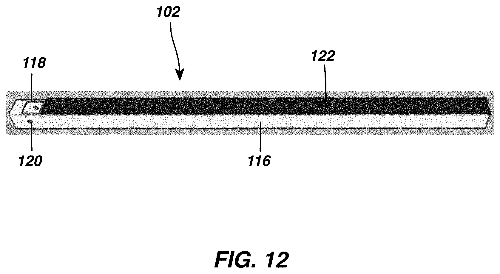
[0032] FIG. 12 shows a perspective view of a horizontal member of a vertical rack system according to one embodiment of the present disclosure;
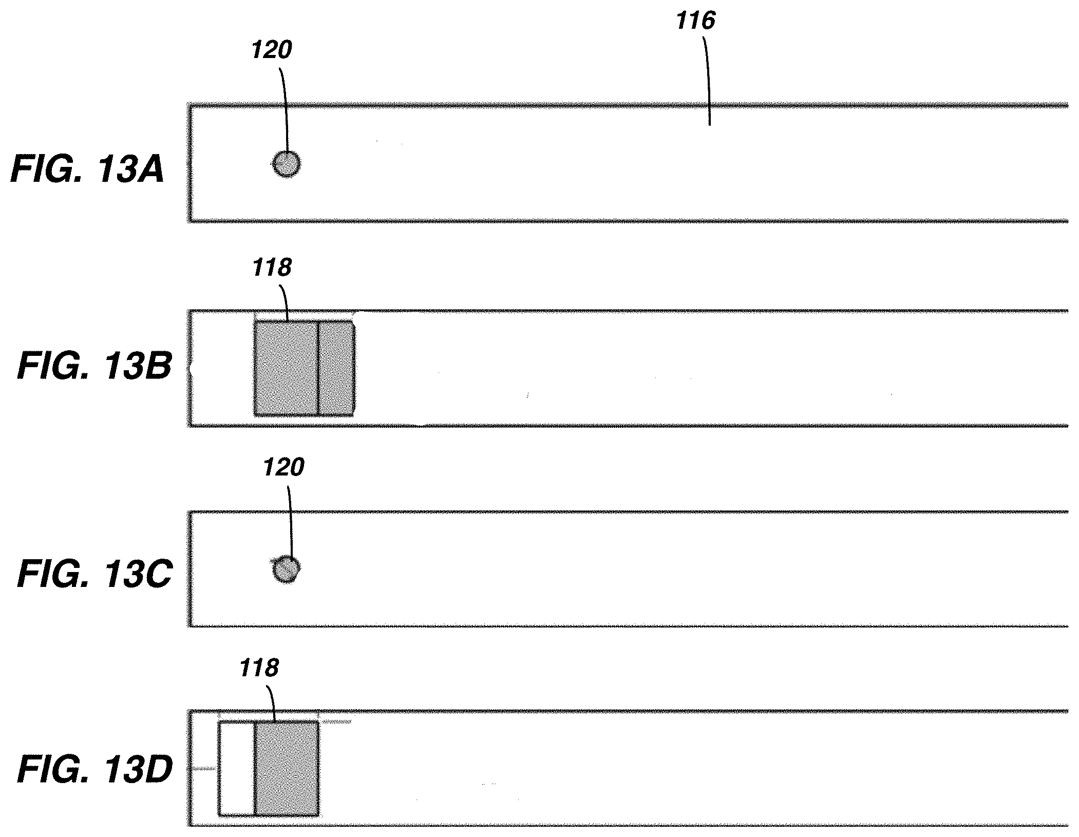
[0033] FIG. 13A shows a first side view of a horizontal member of a vertical rack system according to one embodiment of the present disclosure;
[0034] FIG. 13B shows a top view of a horizontal member of a vertical rack system according to one embodiment of the present disclosure;
[0035] FIG. 13C shows a second side view of a horizontal member of a vertical rack system according to one embodiment of the present disclosure;
[0036] FIG. 13D shows a bottom view of a horizontal member of a vertical rack system according to one embodiment of the present disclosure;
[0037] FIGS. 14A and 14B show a shelf mounted on a rack system according to one embodiment of the present disclosure;
[0038] FIG. 15 shows a collapsible bracket of a rack system according to one embodiment of the present disclosure; and
[0039] FIG. 16 shows a foldable member of a collapsible bracket according to one embodiment of the present disclosure.
DETAILED DESCRIPTION
[0040] Various terms used herein are intended to have particular meanings. Some of these terms are defined below for the purpose of clarity. The definitions given below are meant to cover all forms of the words being defined (e.g., singular, plural, present tense, past tense). If the definition of any term below diverges from the commonly understood and/or dictionary definition of such term, the definitions below control.
[0041] FIGS. 1A-1C show a basic embodiment of a rack system 10 for supporting various items on a surface, such as a ceiling or wall. The rack system 10 is configured to support various types of equipment with various supporting attachments adjustably mounted on the rack system 10. The rack system 10 of the present disclosure is advantageously configured to support various types of items such as tool, sporting equipment, and other various items on the surface and off of a floor of an area of interest. Embodiments herein are particularly suitable for mounting in an area such as a garage to hold items in the garage off of the floor.
[0042] The rack system 10 includes an elongate beam 12 extending from a first end 14 to a second end 16 that is distal from the first end 14. The elongate beam 12 preferably has a rectangular cross-sectional area and is hollow along a length of the elongate beam 12. The elongate beam 12 is preferably formed of a metal, such as steel or aluminum. While the elongate beam 12 preferably has a rectangular cross sectional area, it is understood that a cross sectional area of the elongate beam 12 may be various other suitable shapes for supporting items thereon as described in greater detail below. For example, the elongate beam 12 may be formed having an open channel formed along a length of the elongate beam 12, such that the elongate beam 12 is forms a C-channel.
[0043] The elongate beam 12 preferably has a length of from about 30'' to about 80'', and more preferably has a length of from about 40'' to about 50''. The elongate beam 12 preferably has a height of from about 1'' to about 2'', and more preferably has a height of approximately 1.25''. The elongate beam 12 has a width of from about 1'' to about 2'', and more preferably has a width of approximately 1.25''. While the above dimensions are provided with respect to preferable embodiments of the elongate beam 12, it is also understood that dimensions of the elongate beam 12 may be varied. Further, the elongate beam 12 may be provided in multiple sections that are joined together, such as with fasteners.
[0044] The elongate beam 12 includes a plurality of apertures 18 formed through opposing sides of the elongate beam 12, as shown in FIG. 2. The plurality of apertures 18 preferably have a diameter of approximately 0.5'' and are aligned on opposing sides of the elongate beam 12. The plurality of apertures 18 are preferably uniformly spaced apart along a length of the elongate beam 12 for engaging one or more attachments as described below. The plurality of apertures 18 are preferably spaced apart at a distance of from approximately 0.5'' to approximately 1.5'' and are more preferably spaced apart at a distance of 1'' between apertures 18. The plurality of aperture 18 are preferably located on upper and lower surfaces of the elongate beam 12 when the elongate beam 12 is installed on a mounting surface as described below. While the above spacing and dimensions of the plurality of apertures 18 are preferable, it is also understood that embodiments of the rack system 10 may include apertures having varying spacing and sizes.
[0045] Referring again to FIG. 1A, the rack system 10 includes two or more mounts 20A and 20B for securing the rack system 10 to a surface, such as a wall or ceiling. As shown in FIG. 3, the two or more mounts 20A and 20B are preferably located proximate to the first end 14 and the second end 16 of the elongate beam 12. The two or more mounts 20A and 20B are preferably spaced apart such that the two or more mounts 20A and 20B support a weight of the elongate beam 12 and any attachments thereto.
[0046] Each of the two or more mounts 20A and 20B includes an L-shaped body 22 (FIG. 3). The L-shaped body 22 includes one or more mounting bores 24 formed therethrough for receiving one or more fasteners through the L-shaped body 22 to secure the L-shaped body 22 to a surface. The L-shaped body 22 further includes a support aperture 26 (FIG. 5A) formed on a portion of the L-shaped body 22 that is perpendicular to the portion through which the one or more mounting bores 24 are formed. The support aperture 26 is preferably sized such that an inner shape of the support aperture 26 fits closely around an outer shape of the elongate beam 12. The support aperture 26 is preferably sized such that the elongate beam 12 may freely slide through an inner portion of the support aperture 26 while preventing the elongate beam 12 from rotating or otherwise moving in a direction other than laterally through the support aperture 26.
[0047] As shown in FIGS. 3-5, the support aperture 26 is preferably rectangular in shape such that the support aperture 26 corresponds to a shape of a rectangular elongate beam 12 slidably engaged with the support aperture 26. The two or more mounts 20A are preferably located towards the first end 14 and the second end 16 of the elongate beam 12 when the rack system 10 is installed on a surface. The two or more mounts 20A and 20B are preferably located such that a portion of the elongate beam 12 extends outboard of both of the two or more mounts 20A and 20B as shown in FIGS. 1B and 1C. Further, the outboard portions of the elongate beam 12 preferably include at least one of the plurality of apertures 18 extending outboard of the two or more mounts 20A and 20B.
[0048] In a horizontal arrangement of the elongate support beam 12 of the rack system 10, the support aperture 26 may be formed within the two or more mounts 20A and 20B such that at least one side of the rectangular support aperture 26 is parallel to a surface on which the two or mounts 20A and 20B are secured. Alternatively, and as shown in FIG. 5B, the support aperture 26 may be formed through the two or more mounts 20A and 20B at an angle .theta. relative to a surface on which the two or more mounts 20A and 20B are secured to facilitate supporting an item on the rack system 10 as discussed below. The support aperture 26 is preferably shaped such that the elongate beam 12 is supported at a distance of from about 0.1'' to about 0.5'' from a surface on which the two or more mounts 20A and 20B are mounted, and more preferably at a distance of approximately 0.25''.
[0049] Referring again to FIG. 1A, the rack system 10 further includes one or more attachments 28 adjustably mounted on the rack system 10 for supporting one or more items on the rack system 10. Each of the one or more attachments 28 is preferably removably mounted on the elongate beam 12 of the rack system 10 and is configured such that a location of the one or more attachments 28 is adjustable on the elongate beam 12.
[0050] FIG. 6A illustrates an exemplary embodiment of an attachment 28 that is mountable on the elongate beam 12 of the rack system 10. The attachment 28 includes a clip portion 30 shaped to fit at least partially around the elongate beam 12. The clip portion 30 is preferably shaped such that the clip portion 30 closely fits around three sides of the rectangular beam 12 while allowing the clip portion 30 to be removed from or slidably adjusted along the elongate beam 12. The clip portion 30 includes a pair of opposing apertures 32 formed therethrough, the opposing apertures 32 aligned with one another through opposite sides of the clip portion 30. The pair of opposing apertures 32 are alignable with the plurality of apertures formed through opposing sides of the elongate beam 12 to secure the attachment 28 to the elongate beam 12 as discussed in greater detail below. The pair of opposing apertures preferably have a diameter of approximately 0.5'' and are shaped to receive a pin 34 therethrough, as shown in FIG. 7.
[0051] The attachment of FIGS. 6A-6C includes a pair of parallel arms 36 for supporting items such as tools, skis, and other sporting goods or items. In the embodiment of FIGS. 6A-6C, the pair of parallel arms 36 extends substantially perpendicular to the clip portion 30 and includes upwardly curved end portions 38. Referring to FIG. 6C, in one embodiment the pair of parallel arms 36 is angled upwards relative to horizontal along a length of the pair of parallel arms 36 extending from the clip portion 30. The pair of parallel arms 36 are preferably angled upward at an angle of from about 1.degree. to about 5.degree., and more preferably at an angle of approximately 3.degree..
[0052] To install the rack system 10 of FIGS. 1-7 on a surface, the two or more mounts 20A and 20B are first secured to the surface by inserting one or more fasteners through the mounting bores 24 and into the surface, such as studs on a wall or ceiling surface. The two or more mounts 20A and 20B are preferably installed at a width that is less than a length of the elongate beam 12 and more preferably at a distance that allows for some of the plurality of apertures 18 to be located outboard of each of the mounts 20A and 20B.
[0053] After securing the two or more mounts 20A and 20B to a surface, the elongate beam 12 is next slidably positioned within the support aperture 26 of each of the two or more mounts 20A and 20B. After slidably positioning the elongate beam 12 on the two or more mounts 20A and 20B, a plurality of the attachments 28 are secured on the elongate beam 12 such that items may be hung from or supported on the attachments 28.
[0054] In a preferable embodiment and as shown in FIG. 8, at least two of the attachments 28 are located outboard of the two or more mounts 20A and 20B and secured in place by inserting the pin 34 through the opposing apertures 32 of the attachment 28 and through a pair of the plurality of apertures 18 of the elongate beam. While reference is made to use of a pin to secure the attachments 28 to the elongate beam 12, it is also understood that various other fasteners may be engaged with the elongate beam 12 to secure a position of the attachments 28 on the elongate beam.
[0055] When one of the attachments 28 is located outboard of each of the two or more mounts 20A and 20B, lateral movement of the beam 12 is prevented by the attachments 28 to prevent the elongate beam from disengaging the two or more mounts 20A and 20B. While the above preferable embodiment contemplates attachments 28 mounted outboard of the two or more mounts 20A and 20B, it is also understood that the attachments 28 may otherwise be positioned adjacent to the two or more mounts 20A and 20B to prevent substantial sliding movement of the elongate beam 12 relative to the two or more mounts 20A and 20B.
[0056] Referring now to FIG. 9, in another embodiment the elongate beam 12 may be oriented vertically with respect to a mounting surface to form a vertical rack 100. As shown in FIG. 9, a pair of the elongate beams 12 is preferably mounted vertically along a surface for supporting one or more items on the vertical rack 100. The vertical rack 100 includes a plurality of elongate horizontal members 102 extending substantially perpendicular from the elongate beams 12 to support items on the horizontal members 102. The vertical rack 100 is preferably supported on a surface with a plurality of wall brackets 104 releasably engaged with the elongate beams 12 as discussed in greater detail below.
[0057] Referring to FIG. 10, the plurality of wall brackets 104 are shaped to support the elongate beams 12 in a vertical orientation relative to a support surface, such as a wall. The plurality of wall brackets 104 include opposing tabs 106 and 108 (FIG. 11) including apertures 110 formed therethrough. The apertures 110 are aligned on the opposing tabs 106 and 108 such that a pin may be inserted through the opposing tabs 106 and opposing apertures 18 of the elongate beam 12. The plurality of wall brackets 104 include a base portion 112 oriented perpendicular to the opposing tabs 106 and 108. The base portion 112 includes at least one aperture 114 formed therethrough for receiving a fastener to secure the plurality of wall brackets 104 to a surface.
[0058] Referring now to FIG. 12, each of the plurality of elongate horizontal members 102 includes an elongate body 116. The elongate body 116 preferably has a rectangular cross-sectional area along a length of the elongate body 116. The horizontal members 102 are preferably supported on the vertical beams 12 at an angle such that the horizontal members 102 are angled upward from an end adjacent the vertical beams to distal ends of the horizontal members 102 as shown in FIGS. 9 and 10.
[0059] As shown in FIGS. 13A-13D, the horizontal members 102 include rectangular cutouts 118 formed through opposing sides of the horizontal members 102 that are shaped to fit around the elongate beams 12. The rectangular cutouts 118 are preferably horizontally offset such that when the rectangular cutouts 118 are slidably fit over the elongate beams 12 the horizontal members 102 are supported at an upward angle relative to perpendicular from the vertically oriented elongate beams 12. The horizontal members 102 further include a pair of opposing apertures 120 formed through the elongate body 116 proximate to the opposing apertures 120 such that a pin or other fastener may be inserted through the opposing apertures 120 and apertures 18 of the elongate beams 12 to secure the horizontal members 102 in position.
[0060] The horizontal members 102 further preferably include a padded surface 122 formed on an upper portion of the horizontal members 102 to prevent damage to any items resting on top of the horizontal members 102. The padded surface 122 may be formed from felt, rubber, or other soft or resiliently flexible materials.
[0061] To install the vertical rack 100, the plurality of wall brackets 104 are first mounted on a surface such as a wall by inserting fasteners through the aperture 114 formed through the base portion and into the surface. Prior to installing the elongate beams 12 on the wall brackets 104, the horizontal members 102 may be slidably engaged around the elongate beams 12 and secured in a desired position by inserting a pin through the apertures 120 formed through the elongate body 116 of the horizontal members 102. The elongate beam 12 and horizontal members 102 secured thereto may subsequently be installed on the wall brackets 14 by inserting a pin through the apertures 110 formed through the opposing tabs 106 and 108 and through apertures of the elongate beam 12.
[0062] Referring now to FIGS. 14A and 14B, in yet another embodiment a rack system may further include a shelf 200 formed as part of the rack system for supporting items above the rack system. The shelf 200 is supported on one or more collapsible brackets 202A and 202B that enable the shelf 200 to move between a folded position against a surface on which the shelf 200 is attached and an unfolded position as shown in FIGS. 14A and 14B.
[0063] Referring to FIG. 15, each of the one or more collapsible brackets 202A includes a base portion 204 and a foldable member 206 pivotally mounted on the base portion 204. The base portion 204 includes an aperture 208 formed therethrough for receiving a fastener, such as a removable pin, for securing the foldable member 206 in the unfolded position. A lower end of the base portion 204 is shaped to support the elongate beam 12 according to embodiments described above.
[0064] Referring now to FIG. 16, the foldable member 206 includes a pivot aperture 210 for receiving a pivot pin or other similar member around which the foldable member 206 pivots with respect to the base portion 204. The foldable member 206 further includes an elongate aperture 212 for receiving the pin inserted through the aperture 208 of the base portion to support the shelf 200 in the unfolded position.
[0065] Embodiments of rack systems described herein advantageously allow for various items to be adjustably supported on a surface, such as a wall or ceiling. A location of items mounted on the rack systems may be readily adjusted without requiring tools or substantial disassembly of the rack systems and provide a sturdy mount for various types of items to be secured on the rack systems.
[0066] The foregoing description of preferred embodiments of the present disclosure has been presented for purposes of illustration and description. The described preferred embodiments are not intended to be exhaustive or to limit the scope of the disclosure to the precise form(s) disclosed. Obvious modifications or variations are possible in light of the above teachings. The embodiments are chosen and described in an effort to provide the best illustrations of the principles of the disclosure and its practical application, and to thereby enable one of ordinary skill in the art to utilize the concepts revealed in the disclosure in various embodiments and with various modifications as are suited to the particular use contemplated. All such modifications and variations are within the scope of the disclosure as determined by the appended claims when interpreted in accordance with the breadth to which they are fairly, legally, and equitably entitled.
* * * * *
D00000
D00001
D00002
D00003
D00004
D00005
D00006
D00007
D00008
D00009
D00010
D00011
D00012
D00013

D00014

XML
uspto.report is an independent third-party trademark research tool that is not affiliated, endorsed, or sponsored by the United States Patent and Trademark Office (USPTO) or any other governmental organization. The information provided by uspto.report is based on publicly available data at the time of writing and is intended for informational purposes only.
While we strive to provide accurate and up-to-date information, we do not guarantee the accuracy, completeness, reliability, or suitability of the information displayed on this site. The use of this site is at your own risk. Any reliance you place on such information is therefore strictly at your own risk.
All official trademark data, including owner information, should be verified by visiting the official USPTO website at www.uspto.gov. This site is not intended to replace professional legal advice and should not be used as a substitute for consulting with a legal professional who is knowledgeable about trademark law.