Highly Tunable Magnetic Liquid Crystals
Yin; Yadong ; et al.
U.S. patent application number 16/457816 was filed with the patent office on 2019-12-12 for highly tunable magnetic liquid crystals. The applicant listed for this patent is The Regents of the University of California. Invention is credited to Mingsheng Wang, Yadong Yin.
| Application Number | 20190377215 16/457816 |
| Document ID | / |
| Family ID | 54288297 |
| Filed Date | 2019-12-12 |


| United States Patent Application | 20190377215 |
| Kind Code | A1 |
| Yin; Yadong ; et al. | December 12, 2019 |
HIGHLY TUNABLE MAGNETIC LIQUID CRYSTALS
Abstract
In various embodiments magnetically actuated liquid crystals are provided as well as method of manufacturing such, methods of using the liquid crystals and devices incorporating the liquid crystals. In one non-limiting embodiment the liquid crystals comprise Fe.sub.3O.sub.4 nanorods where the nanorods are coated with a silica coating.
| Inventors: | Yin; Yadong; (Riverside, CA) ; Wang; Mingsheng; (Lake Forest, CA) | ||||||||||
| Applicant: |
|
||||||||||
|---|---|---|---|---|---|---|---|---|---|---|---|
| Family ID: | 54288297 | ||||||||||
| Appl. No.: | 16/457816 | ||||||||||
| Filed: | June 28, 2019 |
Related U.S. Patent Documents
| Application Number | Filing Date | Patent Number | ||
|---|---|---|---|---|
| 15301699 | Oct 3, 2016 | 10359678 | ||
| PCT/US15/24541 | Apr 6, 2015 | |||
| 16457816 | ||||
| 61976364 | Apr 7, 2014 | |||
| Current U.S. Class: | 1/1 |
| Current CPC Class: | C09K 2019/521 20130101; H01F 1/0302 20130101; C09K 19/54 20130101; C09K 19/38 20130101; G02F 2001/133531 20130101; H01F 1/0018 20130101; G02F 1/133553 20130101; G02F 1/133528 20130101; G02F 1/141 20130101; H01F 1/0081 20130101; B82Y 20/00 20130101; G02F 1/0036 20130101; B82Y 40/00 20130101; G02F 1/13768 20130101 |
| International Class: | G02F 1/137 20060101 G02F001/137; H01F 1/00 20060101 H01F001/00; G02F 1/1335 20060101 G02F001/1335; C09K 19/54 20060101 C09K019/54; C09K 19/38 20060101 C09K019/38; G02F 1/00 20060101 G02F001/00 |
Goverment Interests
STATEMENT OF GOVERNMENTAL SUPPORT
[0002] This work was supported in part by Grant No DNR00956081 from the National Science Foundation. The Government has certain rights in this invention.
Claims
1-91 (canceled)
92. A method of making a thin film patterned with one or more optical polarizations, said method comprising: providing a substrate having deposited thereon a resin containing magnetic nanorods, where said magnetic nanorods are coated with a silica and/or polymer layer and form a stable colloidal dispersion, where said magnetic nanorods function as a liquid crystal that performs optical switching in response to a magnetic field; applying a magnetic field to said resin to align said magnetic nanorods in all or in one or more regions of said substrate coated with said resin; and curing/crosslinking said resin in all or in one or more regions of said substrate coated with said resin to fix said magnetic nanorods in a first alignment thereby providing a first optical polarization.
93. The method of claim 92, further comprising: applying a magnetic field to a second region of said substrate to align magnetic nanorods in said second region in an orientation different than said first alignment; and curing/crosslinking said resin in said second region to fix the magnetic nanorods aligned in the second region in a second alignment to provide a second optical polarization.
94. The method of claim 92, further comprising: applying a magnetic field to a third region of said substrate to align said magnetic nanorods in said third region in an orientation different than said first alignment and/or said second alignment; and curing/crosslinking said resin in third second region to fix the magnetic nanorods aligned in the third region in a third alignment to provide a third optical polarization.
95. The method of claim 92, wherein said method comprises leaving the resin in one or more regions uncured/uncrosslinked so that the magnetic nanorods in said regions reorient when a magnetic field is applied to said film.
96. The method of claim 92, wherein said resin is a UV cured resin and said curing/crosslinking by application of UV light to the region that is to be cured/cross-linked.
97. The method of claim 96, wherein said resin is selected from the group consisting of bisphenol-A-diglycidyl-ether-diacrylate (B GEDA), polyethylene-glycoldiacrylate (PEGDA), and poly(diethylene-glycol-carbonate):diacrylate (PGCDA).
98. The method of claim 92, wherein said resin is a chemically cured resin and said curing/crosslinking by application of the curing catalyst to the region that is to be cured/cross-linked.
99. The method of claim 98, wherein said catalyst is inkjet nanoprinted on the region(s) to be cured.
100. A thin film patterned with one or more optical polarizations, said thin film comprising: magnetic nanorods, where said magnetic nanorods are coated with a silica and/or polymer layer and form a stable colloidal dispersion, where said magnetic nanorods function as a liquid crystal that performs optical switching in response to a magnetic field, and where the magnetic nanorods are disposed in one or more predetermined orientations at different locations in said thin film.
101. The thin film of claim 100, wherein said film comprises one or more first regions comprising magnetic nanorods aligned in a first alignment providing a first polarization.
102. The thin film of claim 101, wherein said film comprises one or more second regions comprising magnetic nanorods aligned in a second alignment different from said first alignment providing a second polarization different from said first polarization.
103. The thin film of claim 102, wherein said film comprises one or more third regions comprising magnetic nanorods aligned in a third alignment different from said first and/or said second alignment providing a third polarization different from said first and/or said second polarization.
104. The thin film of claim 100, wherein said film comprises one or more regions wherein the magnetic nanorods in said regions are free to reorient when a magnetic field is applied to said film.
105. The thin film of claim 100, wherein said film is made according to the method of claim 92.
Description
CROSS-REFERENCE TO RELATED APPLICATIONS
[0001] This application is a divisional of U.S. Ser. No. 15/301,699, filed on Oct. 3, 2016, which is a US 371 National Phase of PCT/US2015/024541, filed on Apr. 6, 2015, which claims benefit of and priority to U.S. Ser. No. 61/976,364, filed on Apr. 7, 2014, all of which are incorporated herein by reference in their entirety for all purposes.
BACKGROUND
[0003] Development of magnetic-responsive liquid crystals (LCs) is of both fundamental and practical importance since it not only represents an ideal system in condensed matter that allows exploration of phase complexity in a single sample as the external field changes, but it also opens the way towards various applications that benefit from the instantaneous and contactless nature of magnetic interactions.
[0004] Conventional liquid crystals (LCs) are mostly insensitive to magnetic fields. Limited by the low magnetic susceptibility of their components, most studies on previous liquid crystals focus only on the phase behavior of LCs under magnetic fields. It is believed the use of magnetically tunable liquid crystals for practical applications, such as optical switching, has never been demonstrated.
SUMMARY
[0005] In various embodiments magnetically actuated liquid crystals are provided as well as method of making the magnetically actuated liquid crystals, methods of using the magnetically actuated liquid crystals (e.g., in optical switching applications, displays, anti-counterfeiting devices and the like), methods of fixing the orientation of the components in the liquid crystals and producing patterns of polarization in the fixed liquid crystals, and devices comprising the magnetically actuated liquid crystals. In certain embodiments the liquid crystals comprise magnetic anisotropic nanostructures (e.g., nanorods) whose surfaces are modified for dispersion if necessary, e.g., coated with a polymer or a silica layer. In certain embodiments the nanostructures are coated with a layer of silica.
[0006] In one illustrative, but non-limiting embodiment, liquid crystals are provided that comprise Fe.sub.3O.sub.4 nanorods where the nanorods are coated with a silica coating. In certain embodiments the nanorods are provided as a suspension and/or dispersion.
[0007] Various embodiments contemplated herein may include, but need not be limited to, one or more of the following:
[0008] Embodiment 1: A liquid crystal, said liquid crystal including: a suspension/dispersion of magnetic anisotropic nanostructures.
[0009] Embodiment 2: The liquid crystal of embodiment 1, wherein said anisotropic nanostructure includes a material selected from the group consisting of a ferromagnetic material, a ferromagnetic material, and a superparamagnetic material.
[0010] Embodiment 3: The liquid crystal according to any one of embodiments 1-2, wherein said anisotropic nanostructure includes a material selected from the group consisting of metallic iron, metallic cobalt, metallic nickel, metallic gadolinium, metallic dysprosium, an alloy containing iron, an alloy containing cobalt, an alloy containing nickel, an alloy containing gadolinium, an alloy containing dysprosium, an oxide of iron, an oxide of cobalt, an oxide of nickel, an oxide of manganese, an oxide of europium, and an oxide of chromium.
[0011] Embodiment 4: The liquid crystal of embodiment 2, wherein said lanisotropic nanostructure includes Fe.sub.3O.sub.4.
[0012] Embodiment 5: The liquid crystal according to any one of embodiments 1-4, wherein said anisotropic structures comprise anisotropic nanostructures selected from the group consisting of nanorods, nanoplates, nanotubes, and nanodiscs.
[0013] Embodiment 6: The liquid crystal according to any one of embodiments 1-4, wherein said anisotropic structures comprise nanorods.
[0014] Embodiment 7: The liquid crystal according to any one of embodiments 1-6, wherein the average length of the long axis of said anisotropic structures ranges from about 20 nm up to about 10 .mu.m.
[0015] Embodiment 8: The liquid crystal of embodiment 7, wherein the average length of the long axis of said anisotropic structures ranges from about 50 nm up to about 10 .mu.m, or from about 100 nm up to about 5 .mu.m.
[0016] Embodiment 9: The liquid crystal of embodiment 7, wherein the average length of the long axis of said anisotropic structures ranges from about 20 nm, or from about 50 nm, or from about 100 nm, or from about 200 nm, or from about 300 nm, or from about 400 nm, or from about 500 nm up to about 10 .mu.m, up to about 5 .mu.m, or up to about 4 .mu.m, or up to about 3 .mu.m, or up to about 2 .mu.m.
[0017] Embodiment 10: The liquid crystal of embodiment 7, wherein the average length of the long axis of said structures is about 1.5 .mu.m.
[0018] Embodiment 11: The liquid crystal according to any one of embodiments 1-10, wherein the average length of the short axis of said anisotropic structures ranges from about 2 nm up to about 1 .mu.m, or from about 100 nm up to about 500 nm, or from about 100 nm up to about 300 nm.
[0019] Embodiment 12: The liquid crystal according to any one of embodiments 1-10, wherein the average length of the short axis of said anisotropic structures ranges from about 2 nm or from about 5 nm, or from about 10 nm, or from about 20 nm, or from about 30 nm, or from about 40 nm, or from about 50 nm, or from about 60 nm, or from about 70 nm, or from about 80 nm, or from about 90 nm, or from about 100 nm, up to about 1 .mu.m, or up to about 800 nm, or up to about 500 nm, or up to about 400 nm, or up to about 300 nm.
[0020] Embodiment 13: The liquid crystal according to any one of embodiments 1-10, wherein the average length of the short axis of said anisotropic structures is about 200 nm.
[0021] Embodiment 14: The liquid crystal according to any one of embodiments 1-13, wherein the ratio of the length of the long axis to the length of the short axis of said anisotropic structures is at least about 1.1 or at least about 1.2, or at least about 1.3, or at least about 1.5, or at least about 2, or at least about 3, or at least about 4, or at least about 5, or at least about 6, or at least about 7, or at least about 8, or at least about 9, or at least about 10, or at least about 11, or at least about 12, or at least about 13, or at least about 14, or at least about 15, or at least about 16, or at least about 17, or at least about 18, or at least about 19, or at least about 20.
[0022] Embodiment 15: The liquid crystal according to any one of embodiments 1-14, wherein the surface of said nanostructures is modified to ensure dispersion/suspension in a solvent.
[0023] Embodiment 16: The liquid crystal of embodiment 15, wherein the surface of said nanostructure is functionalized with a hydrophilic group.
[0024] Embodiment 17: The liquid crystal of embodiment 16, wherein the surface of said nanostructure is functionalized with a group selected from the group consisting of hydroxyl, carboxyl, sulfhydryl, carbonyl, amino, and phosphate.
[0025] Embodiment 18: The liquid crystal of embodiment 15, wherein the surface of said nanostructure has a polymer layer or a silica layer thereon.
[0026] Embodiment 19: The liquid crystal of embodiment 15, wherein the surface of said nanostructure has a silica layer thereon.
[0027] Embodiment 20: The liquid crystal according to any one of embodiments 1-19, wherein said anisotropic nanostructures are suspended/dispersed in a polar solvent, a non-polar solvent, or a mixture of polar and non-polar solvents.
[0028] Embodiment 21: The liquid crystal of embodiment 26, wherein said anisotropic nanostructures are suspended/dispersed in a polar solvent.
[0029] Embodiment 22: The liquid crystal of embodiment 26, wherein said anisotropic nanostructures are suspended/dispersed in a solution including water.
[0030] Embodiment 23: The liquid crystal of embodiment 26, wherein said anisotropic nanostructures are suspended/dispersed in a solution including an alcohol.
[0031] Embodiment 24: The liquid crystal of embodiment 23, wherein said anisotropic nanostructures are suspended/dispersed in a solution including an alcohol selected from the group consisting of methanol, ethanol, propanol, 1-butanol, 2-butanol, 2-methyl-1 propanol, 2-methyl-2-propanol, ethylene glycol, methylene glycol, propylene glycol, glycerol, benzyl alcohol, cinnamic alcohol, diethylene glycol, grandisol, cyclohexanol, and octanol.
[0032] Embodiment 25: The liquid crystal of embodiment 23, wherein said anisotropic nanostructures are suspended/dispersed in a solution including ethylene glycol.
[0033] Embodiment 26: The liquid crystal of embodiment 23, wherein said anisotropic nanostructures are suspended/dispersed in a non-polar solvent.
[0034] Embodiment 27: The liquid crystal according to any one of embodiments 1-26, wherein the volume fraction of anisotropic nanostructures in said suspension/dispersion is greater than about 0.1%.
[0035] Embodiment 28: The liquid crystal of embodiment 27, wherein the volume fraction of anisotropic nanostructures in said suspension/dispersion ranges from about 0.1% up to about 70%.
[0036] Embodiment 29: The liquid crystal according to any one of embodiments 27-28, wherein the volume fraction of anisotropic nanostructures in said suspension/dispersion is greater than about 0.5%, or greater than about 1%, or greater than about 3%, or greater than about 4%, or greater than about 3%, or greater than about 5%, or greater than about 6%, or greater than about 7%, or greater than about 8%, or greater than about 9%, or greater than about 10%, or greater than about 11%, or greater than about 12%, or greater than about 13%, or greater than about 14%, or greater than about 15%, or greater than about 16%, or greater than about 17%, or greater than about 18%, or greater than about 19%, or greater than about 20%.
[0037] Embodiment 30: The liquid crystal according to any one of embodiments 1-26, wherein the volume fraction of anisotropic nanostructures in said suspension/dispersion is about 10%.
[0038] Embodiment 31: The liquid crystal according to any one of embodiments 27-30, wherein the volume fraction of anisotropic structures in said suspension is sufficient to provide ordered liquid crystalline phases.
[0039] Embodiment 32: The liquid crystal according to any one of embodiments 1-31, wherein the anisotropic structures reorient in a magnetic field having intensity less than about 1T.
[0040] Embodiment 33: The liquid crystal of embodiment 32, wherein the anisotropic structures reorient in a magnetic field having an intensity less than about 800 mT, or less than bout 500 mT, or less than about 400 mT, or less than about 300 mT, or less than about 200 mT, or less than about 100 mT, or less than about 50 mT, or less than about 25 mT, or less than about 10 mT, or less than about 5 mT, or at about 1 mT.
[0041] Embodiment 34: The liquid crystal according to any one of embodiments 1-33, wherein the anisotropic structures are suspended/dispersed in a solution containing polymer or pre-polymer molecules.
[0042] Embodiment 35: A device including: a first polarizing layer or film configured to act as a polarizer; a second polarizing layer or film; and a liquid crystal according to any one of embodiments 1-34 disposed between said first polarizing layer or film and said second polarizing layer or film.
[0043] Embodiment 36: The device of embodiment 35, wherein said first polarizing layer or film is configured to act as a polarizer.
[0044] Embodiment 37: The device of according to any one of embodiments 35-36, wherein said second polarizing layer or film is configured to act as an analyzer.
[0045] Embodiment 38: The device of according to any one of embodiments 35-37, wherein the angle of polarization of said first polarizing layer or film differs from the angle of polarization of said second polarizing layer or film.
[0046] Embodiment 39: The device of embodiment 38, wherein the angle of polarization of said first polarizing layer or film and the angle of said second polarizing layer or film differ by an amount that ranges from about 0 degrees to about 180 degrees.
[0047] Embodiment 40: The device of embodiment 39, wherein the angle of polarization of said first polarizing layer or film and the angle of said second polarizing layer or film differ by about 45 degrees.
[0048] Embodiment 41: The device of embodiment 39, wherein the angle of polarization of said first polarizing layer or film and the angle of said second polarizing layer or film differ by about 90 degrees.
[0049] Embodiment 42: The device of according to any one of embodiments 35-41, wherein said device further includes a reflective layer disposed behind said first polarizing layer or film and sais second polarizing layer or film.
[0050] Embodiment 43: The device of according to any one of embodiments 35-42, wherein said device is a component of an apparatus selected from the group consisting of a display, a waveguide, an actuator, and an optical modulator.
[0051] Embodiment 44: A method of optical switching, said method including: passing a polarized optical signal through a liquid crystal according to any one of embodiments 1-34; and applying a magnetic field to said liquid crystal to alter the transmission of said liquid crystal to said optical signal.
[0052] Embodiment 45: The method of embodiment 44, wherein said magnetic field is switched at a frequency of at least 1 Hz.
[0053] Embodiment 46: The method of embodiment 45, wherein said magnetic field is switched at a frequency of at least 5 Hz, or at least 10 Hz, or at least 20 Hz, or at least 50 Hz, or at least 80 Hz, or at least 100 Hz, or at least 150 Hz, or at least 200 Hz.
[0054] Embodiment 47: The method according to any one of embodiments 44-46, wherein said method is performed using a device according to any one of embodiments 35-43.
[0055] Embodiment 48: A method of fabricating magnetic anisotropic nanostructures for use as magnetic liquid crystals, said method including: preparing nonmagnetic anisotropic nanostructures; modifying the surface of said nanostructures if necessary to ensure solvent dispersity; and converting said nanostructures into magnetic anisotropic nanostructures.
[0056] Embodiment 49: A method of fabricating magnetic anisotropic nanostructures for use as magnetic liquid crystals, said method including: preparing magnetic anisotropic nanostructures; and modifying the surface of said nanostructures if necessary to ensure solvent dispersity.
[0057] Embodiment 50: The method of embodiment 49, wherein said anisotropic structures comprise a material selected from the group consisting of metallic iron, metallic cobalt, metallic nickel, metallic gadolinium, metallic dysprosium, an alloy containing iron, an alloy containing cobalt, an alloy containing nickel, an alloy containing gadolinium, an alloy containing dysprosium, an oxide of iron, an oxide of cobalt, an oxide of nickel, an oxide of manganese, an oxide of europium, and an oxide of chromium.
[0058] Embodiment 51: The method of embodiment 49, wherein said anisotropic structures comprise a material selected from the group consisting of Fe, Co, Ni, Mn, Gd, Dy, Eu, Cr, Zn, Cu, Mg, O, Si, Bi, Y, Sb.
[0059] Embodiment 52: The method of embodiment 49, wherein said anisotropic structures comprise a material selected from the group consisting of compounds of Fe, Co, Ni, Mn, Gd, Dy, Eu, Cr, Zn, Cu, Mg, O, Si, Bi, Y, Sb.
[0060] Embodiment 53: The method of embodiment 49, wherein said anisotropic structures comprise a material selected from the group consisting of alloys of Fe, Co, Ni, Mn, Gd, Dy, Eu, Cr, Zn, Cu, Mg, O, Si, Bi, Y, Sb.
[0061] Embodiment 54: The method of embodiment 49, wherein said anisotropic structures comprise includes Fe.sub.3O.sub.4.
[0062] Embodiment 55: The method according to any one of embodiments 49-54, wherein said anisotropic structures comprise anisotropic nanostructures selected from the group consisting of nanorods, nanoplates, nanotubes, and nanodiscs.
[0063] Embodiment 56: The method according to any one of embodiments 49-54, wherein said anisotropic structures comprise nanorods.
[0064] Embodiment 57: The method according to any one of embodiments 49-56, wherein the average length of the long axis of said anisotropic structures ranges from about 20 nm up to about 10 .mu.m.
[0065] Embodiment 58: The method of embodiment 57, wherein the average length of the long axis of said anisotropic structures ranges from about 50 nm up to about 10 .mu.m, or from about 100 nm up to about 5 .mu.m.
[0066] Embodiment 59: The method of embodiment 57, wherein the average length of the long axis of said anisotropic structures ranges from about 20 nm, or from about 50 nm, or from about 100 nm, or from about 200 nm, or from about 300 nm, or from about 400 nm, or from about 500 nm up to about 10 .mu.m, up to about 5 .mu.m, or up to about 4 .mu.m, or up to about 3 .mu.m, or up to about 2 .mu.m.
[0067] Embodiment 60: The method of embodiment 57, wherein the average length of the long axis of said structures is about 1.5 .mu.m.
[0068] Embodiment 61: The method according to any one of embodiments 49-60, wherein the average length of the short axis of said anisotropic structures ranges from about 2 nm up to about 1 .mu.m, or from about 100 nm up to about 500 nm, or from about 100 nm up to about 300 nm.
[0069] Embodiment 62: The method according to any one of embodiments 49-60, wherein the average length of the short axis of said anisotropic structures ranges from about 2 nm or from about 5 nm, or from about 10 nm, or from about 20 nm, or from about 30 nm, or from about 40 nm, or from about 50 nm, or from about 60 nm, or from about 70 nm, or from about 80 nm, or from about 90 nm, or from about 100 nm, up to about 1 .mu.m, or up to about 800 nm, or up to about 500 nm, or up to about 400 nm, or up to about 300 nm.
[0070] Embodiment 63: The method according to any one of embodiments 49-60, wherein the average length of the short axis of said anisotropic structures is about 200 nm.
[0071] Embodiment 64: The method according to any one of embodiments 49-63, wherein the ratio of the length of the long axis to the length of the short axis of said anisotropic structures is at least about 1.1 or at least about 1.2, or at least about 1.3, or at least about 1.5, or at least about 2, or at least about 3, or at least about 4, or at least about 5, or at least about 6, or at least about 7, or at least about 8, or at least about 9, or at least about 10, or at least about 11, or at least about 12, or at least about 13, or at least about 14, or at least about 15, or at least about 16, or at least about 17, or at least about 18, or at least about 19, or at least about 20.
[0072] Embodiment 65: The method according to any one of embodiments 49-64, wherein said preparing includes preparing nanostructures including FeOOH nanostructures including an FeCl.sub.3 precursor.
[0073] Embodiment 66: The method according to any one of embodiments 49-65, wherein said modifying the surface of said nanostructures includes modifying said surface with a surfactant.
[0074] Embodiment 67: The method according to any one of embodiments 49-65, wherein said modifying the surface of said nanostructures includes functionalizing said surface with a hydophylic group.
[0075] Embodiment 68: The method of embodiment 67, wherein said modifying the surface of said nanostructures includes functionalizing said surface with a group selected from the group consisting of hydroxyl, carboxyl, sulfhydryl, carbonyl, amino, and phosphate.
[0076] Embodiment 69: The method according to any one of embodiments 49-65, wherein said modifying the surface of said nanostructures includes coating said surface with an oxide coating.
[0077] Embodiment 70: The method of embodiment 69, wherein said oxide coating includes silica.
[0078] Embodiment 71: The method of embodiment 70, wherein said modifying the surface of said nanostructures includes reacting said nanostructures with a silica alkoxide.
[0079] Embodiment 72: The method of embodiment 71, wherein said modifying the surface of said nanostructures includes reacting said nanostructures with a silica alkoxide selected from the group consisting of tetraethyl orthosilicate (TEOS), and tetramethyl orthosilicate (TMOS).
[0080] Embodiment 73: The method according to any one of embodiments 49-65, wherein said modifying the surface of said nanostructures includes coating said surface with a polymer coating.
[0081] Embodiment 74: The method according to any one of embodiments 48, and 50-73, wherein said converting said modified nanostructures into magnetic anisotropic nanostructures includes reducing said non-magnetic nanostructures.
[0082] Embodiment 75: The method according to any one of embodiments 48, and 50-73, wherein said converting said modified nanostructures into magnetic anisotropic nanostructures includes reducing FeOOH in said nanostructures to Fe.sub.3O.sub.4.
[0083] Embodiment 76: The method according to any one of embodiments 74-75, wherein said reducing is performed using a material selected from the group consisting of diethylene glycol, ethylene glycol, glycerol, borohydride, hydrazine, and hydrogen.
[0084] Embodiment 77: The method according to any one of embodiments 48-76, wherein said method further includes purifying and/or concentrating said magnetic anisotropic nanostructures.
[0085] Embodiment 78: The method of embodiment 77, wherein said purifying and/or concentrating includes one or more magnetic separation steps.
[0086] Embodiment 79: The method according to any one of embodiments 48-78, wherein said magnetic anisotropic nanostructures are concentrated or resuspended to a volume fraction greater than about 0.1%.
[0087] Embodiment 80: The method according to any one of embodiments 48-78, wherein said magnetic anisotropic nanostructures are concentrated or resuspended to a volume fraction that ranges 0.1% up to about 70%.
[0088] Embodiment 81: The method according to any one of embodiments 48-78, wherein said magnetic anisotropic nanostructures are concentrated or re-suspended to a volume fraction that is greater than about 0.5%, or greater than about 1%, or greater than about 3%, or greater than about 4%, or greater than about 3%, or greater than about 5%, or greater than about 6%, or greater than about 7%, or greater than about 8%, or greater than about 9%, or greater than about 10%, or greater than about 11%, or greater than about 12%, or greater than about 13%, or greater than about 14%, or greater than about 15%, or greater than about 16%, or greater than about 17%, or greater than about 18%, or greater than about 19%, or greater than about 20%.
[0089] Embodiment 82: The method according to any one of embodiments 48-78, wherein said magnetic anisotropic nanostructures are concentrated or re-suspended to a volume fraction sufficient to provide ordered liquid crystalline phases.
[0090] Embodiment 83: The method according to any one of embodiments 48-82, wherein said anisotropic nanostructures are suspended in a polar solvent, a non-polar solvent, or a mixture of polar and non-polar solvents.
[0091] Embodiment 84: The method of embodiment 83, wherein said anisotropic nanostructures are suspended in a polar solvent.
[0092] Embodiment 85: The method of embodiment 83, wherein said anisotropic nanostructures are suspended in a solution including water.
[0093] Embodiment 86: The method of embodiment 83, wherein said anisotropic nanostructures are suspended in a solution including an alcohol.
[0094] Embodiment 87: The method of embodiment 86, wherein said anisotropic nanostructures are suspended in a solution including an alcohol selected from the group consisting of methanol, ethanol, propanol, 1-butanol, 2-butanol, 2-methyl-1 propanol, 2-methyl-2-propanol, ethylene glycol, methylene glycol, propylene glycol, glycerol, benzyl alcohol, cinnamic alcohol, diethylene glycol, grandisol, cyclohexanol, and octanol.
[0095] Embodiment 88: The method of embodiment 86, wherein said anisotropic nanostructures are suspended in a solution including ethylene glycol.
[0096] Embodiment 89: The method of embodiment 83, wherein said anisotropic nanostructures are suspended in a non-polar solvent.
[0097] Embodiment 90: The method of embodiment 83, wherein the anisotropic structures are suspended in a solution containing polymer or pre-polymer molecules.
[0098] Embodiment 91: A liquid crystal including silica-coated magnetic anisotropic nanostructures fabricated according to the method of any one of embodiments 48-90.
[0099] Embodiment 92: A method of making a thin film patterned with one or more optical polarizations, said method including: providing a substrate having deposited thereon a resin containing anisotropic magnetic nanostructures as recited in any one of embodiments 1-34; applying a magnetic field to said resin to align said anisotropic magnetic nanostructures in all or in one or more regions of said substrate coated with said resin; and curing/crosslinking said resin in all or in one or more regions of said substrate coated with said resin to fix said anisotropic magnetic nanostructures in a first alignment thereby providing a first optical polarization.
[0100] Embodiment 93: The method of embodiment 92, further including: applying a magnetic field to a second region of said substrate to align anisotropic magnetic nanostructures in said second region in an orientation different than said first alignment; and curing/crosslinking said resin in said second region to fix the anisotropic magnetic nanostructures aligned in the second region in a second alignment to provide a second optical polarization.
[0101] Embodiment 94: The method according to any one of embodiments 92-93, further including: applying a magnetic field to a third region of said substrate to align said anisotropic magnetic nanostructures in said third region in an orientation different than said first alignment and/or said second alignment; and curing/crosslinking said resin in third second region to fix the nanorods aligned in the third region in a third alignment to provide a third optical polarization.
[0102] Embodiment 95: The method according to any one of embodiments 92-94, wherein said method includes leaving the resin in one or more regions uncured/uncrosslinked so that the anisotropic magnetic nanostructures in said regions reorient when a magnetic field is applied to said film.
[0103] Embodiment 96: The method according to any one of embodiments 92-95, wherein said resin is a UV cured resin and said curing/crosslinking by application of UV light to the region that is to be cured/cross-linked.
[0104] Embodiment 97: The method of embodiment 96, wherein said resin is selected from the group consisting of bisphenol-A-diglycidyl-ether-diacrylate (BGEDA), polyethylene-glycol-diacrylate (PEGDA), and poly(diethylene-glycol-carbonate) diacrylate (PGCDA).
[0105] Embodiment 98: The method according to any one of embodiments 92-95, wherein said resin is a chemically cured resin and said curing/crosslinking by application of the curing catalyst to the region that is to be cured/cross-linked.
[0106] Embodiment 99: The method of embodiment 98, wherein said catalyst is inkjet nanoprinted on the region(s) to be cured.
[0107] Embodiment 100: A thin film patterned with one or more optical polarizations, said thin film including: anisotropic magnetic nanostructures as recited in any one of embodiments 1-34, where the anisotropic magnetic nanostructures are disposed in one or more predetermined orientations at different locations in said thin film.
[0108] Embodiment 101: The thin film of embodiment 100, wherein said film includes one or more first regions including anisotropic magnetic nanostructures aligned in a first alignment providing a first polarization.
[0109] Embodiment 102: The thin film of embodiment 101, wherein said film includes one or more second regions including anisotropic magnetic nanostructures aligned in a second alignment different from said first alignment providing a second polarization different from said first polarization.
[0110] Embodiment 103: The thin film of embodiment 102, wherein said film includes one or more third regions including anisotropic magnetic nanostructures aligned in a third alignment different from said first and/or said second alignment providing a third polarization different from said first and/or said second polarization.
[0111] Embodiment 104: The thin film according to any one of embodiments 100-103, wherein said film includes one or more regions wherein the anisotropic magnetic nanostructures in said regions are free to reorient when a magnetic field is applied to said film.
[0112] Embodiment 105: The thin film according to any one of embodiments 100-104, wherein said film is made according to the method of any one of embodiments 92-99.
BRIEF DESCRIPTION OF THE DRAWINGS
[0113] FIG. 1 shows TEM images of (panel a) FeOOH nanorods and (panel b) Fe.sub.3O.sub.4@SiO.sub.2 nanorods. Scale bars: 1 .mu.m; (panel c) magnetic hysteresis loop of Fe.sub.3O.sub.4@SiO.sub.2 nanorods; (panel d) SEM image of a fixed magnetic liquid crystal in a polymer matrix showing the ordered arrangement of magnetic nanorods. Scale bars: 1 .mu.m; (panel e) POM images of aqueous dispersions of Fe.sub.3O.sub.4@SiO.sub.2 nanorods in a capillary tube at different volume fractions (.PHI.) of 1%, 3%, 5% and 10% (from top to bottom). Scale bars: 500 .mu.m.
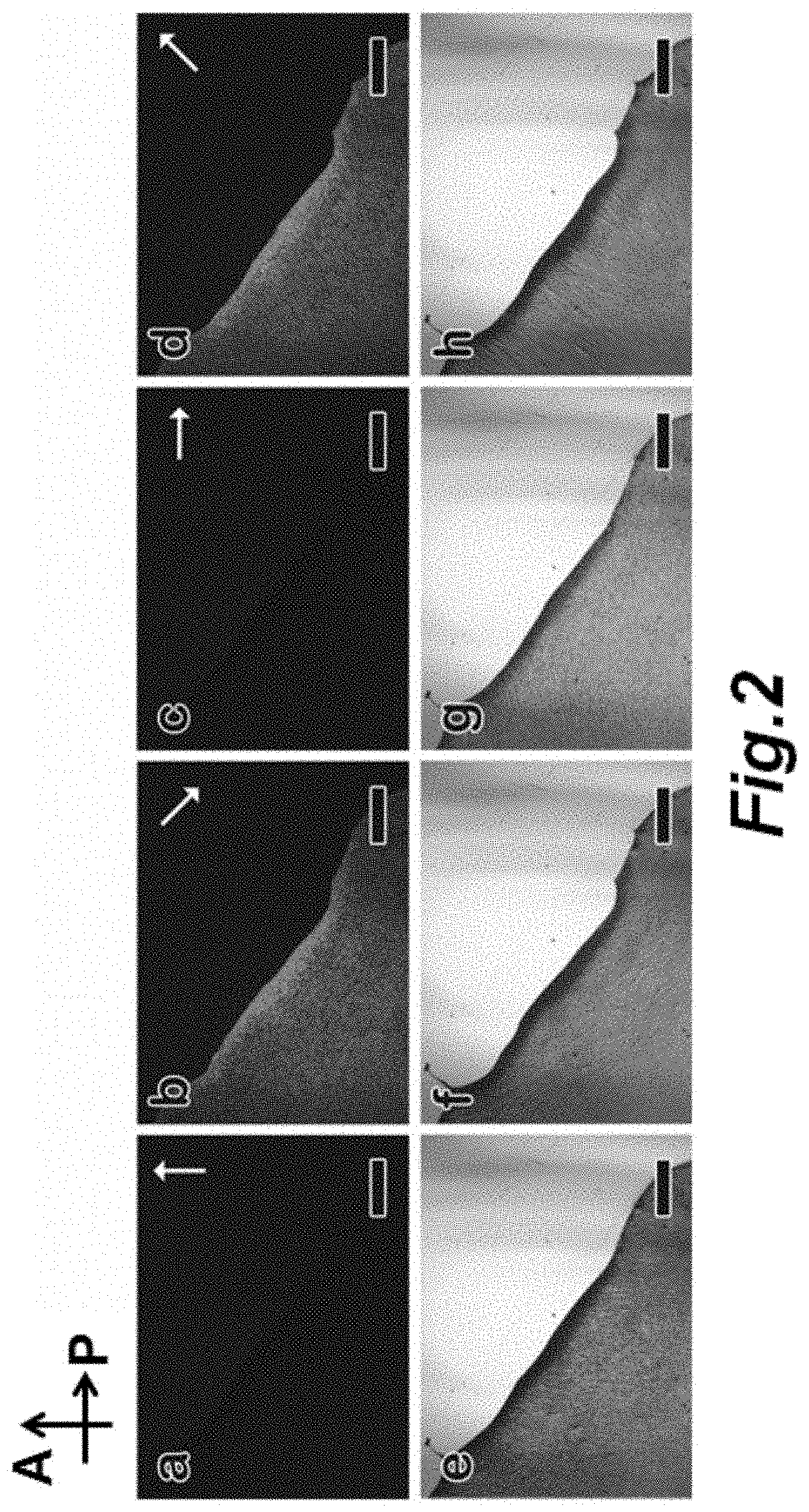
[0114] FIG. 2, (panels a-d) POM images and (panels e-h) bright-field OM images of a magnetic liquid crystal film under magnetic fields oriented in different directions. Black arrows at the top-left indicate the transmission axis of the polarizer (P) and analyzer (A). White arrows indicate the field direction. The top-right corner in each image contains no sample. Scale bars: 500 .mu.m.
[0115] FIG. 3 (panel a) Scheme showing the optical switching process, and (panel b) the transmittance intensity profile of a magnetic liquid crystal under an alternating magnetic field.
[0116] FIG. 4 (panel a) Scheme showing the lithography process for the fabrication of thin films with patterns of different polarizations; (panels b-d) POM images of various polarization-modulated patterns; (panel e) enlarged OM image shows the arrangement of nanorods in the pattern (left) and surrounding area (right). Scale bars: (panels b-d) 500 .mu.m;(panel e) 10 .mu.m
[0117] FIG. 5 (panels a-d) POM images of two polarization-modulated patterns under cross polarizers before (panels a,b) and after (panels c,d) shifting the direction of the transmission axis of the polarizers for 45.degree.; (panels e,f) bright-field images of the same patterns; (panel g) plot showing the dependence of the transmittance of the thin film on the angle between the nanorod orientation and the transmission axis of the polarizer; (panel h) POM image of a single thin film patterned with different brightness in different areas by controlling the relative orientation of the nanorods, which is indicated by the white arrows. Scale bars: 500 .mu.m.
DEFINITIONS
[0118] The terms "suspension" and "dispersion" are used interchangeably herein to refer to nanostructures present in a fluid (or polymerized) medium. In certain embodiments the nanostructures are homogenously dispersed in the medium, while in other embodiments, the nanostructures are not homogenously dispersed. In certain embodiments the nanoparticle provide one or a plurality of phases in the medium.
DETAILED DESCRIPTION
[0119] In various embodiments magnetically actuated liquid crystals are provided as well as method of making the magnetically actuated liquid crystals, methods of using the liquid crystals (e.g., in optical switching applications, displays, and the like), and devices comprising the liquid crystals. In certain embodiments the liquid crystals comprise magnetic anisotropic nanostructures (e.g., nanorods and nanoplates). If necessary, the surfaces of these magnetic anisotropic nanostructures are modified with additional coating for enhanced dispersion in solvents, e.g., coated with a layer of capping ligands, or polymer, or inorganic oxides such as silica. In certain embodiments the nanostructures are coated with a silica layer.
[0120] In one illustrative, but non-limiting embodiment for the fabrication of liquid crystals, superparamagnetic iron oxide nanorods or nanoplates are synthesized, and their surfaces are modified with capping ligands, or oxide such as silica, or polymer for enhanced dispersion (if necessary). The nanorods or nanoplates can be dispersed in a suitable solvent at a certain volume fraction to form magnetically actuated liquid crystals. These liquid crystals show an outstanding magnetic response and magnetic-field-controlled instant and reversible orientation.
[0121] In one illustrative, but non-liming embodiment, for the fabrication of liquid crystals, ferrimagnetic iron oxide nanorods or nanoplates are synthesized, and their surfaces modified with capping ligands, or oxide such as silica, or polymer for enhanced dispersion (if necessary). Then they were dispersed in suitable solvent at a certain volume fraction to form magnetically actuated liquid crystals. These liquid crystals show an outstanding magnetic response and magnetic-field-controlled instant and reversible orientation.
[0122] In one illustrative but non-limiting embodiment, nonmagnetic FeOOH nanorods ARE first synthesized, followed by a coating of silica on their surfaces, and are finally reduced to superparamagnetic or ferrimagnetic iron oxide nanorods encapsulated in a silica layer by diethylene glycol at elevated temperature. The as-reduced nanorods can be dispersed in water or polar solvent at a certain volume fraction, e.g., 10%, and magnetically to provide actuated liquid crystals. Dependent on the volume fraction, this liquid crystal can form nematic or smectic phases. These liquid crystals show an outstanding magnetic response and magnetic-field-controlled instant and reversible orientation tuning is demonstrated.
[0123] In one illustrative, but non-liming embodiment, for the fabrication of liquid crystals,nonmagnetic Ni(OH).sub.2 nanoplates are first synthesized, followed by a coating of SiO.sub.2 on their surfaces, and finally reduced to Fe.sub.3O.sub.4@SiO.sub.2 nanorods by hydrogen. The as-reduced nanoplates were dispersed in water or polar solvent at a certain volume fraction, and magnetically actuated liquid crystals were achieved. Dependent on the volume fraction, this liquid crystal can form nematic or columnar or hexagonal phases. These liquid crystals show an outstanding magnetic response and magnetic-field-controlled instant and reversible orientation.
[0124] In one illustrative, but non-liming embodiment, for the fabrication of liquid crystals, nonmagnetic nanorods or nanoplates were first synthesized, followed by a coating of polymer on their surfaces, and were finally reduced to ferromagnetic core@polymer nanostructures. The as-reduced nanostructures were dispersed in water or polar solvent at a certain volume fraction to form magnetically actuated liquid crystals. These liquid crystals show an outstanding magnetic response and magnetic-field-controlled instant and reversible orientation.
[0125] In one illustrative, but non-liming embodiment, for the application of magnetically actuated liquid crystals in displays, but non-limiting embodiment, magnetically actuated liquid crystals were sandwiched between cross polarizers to form a device. As the field direction changes, this device can tune the transmittance of light. An alternating magnetic field was applied to the device (e.g., 5 mT), the liquid crystal exhibited an optical switching frequency of above 100 Hz, which is comparable to commercial liquid crystals and thus can be a promising substitute for them in device applications. Color filters are attached to this device to create a proto-type of magnetically responsive liquid crystal color display.
[0126] In one illustrative, but non-liming embodiment, for the application of magnetically actuated liquid crystals in polarization pattern printing, but non-limiting embodiment, magnetically actuated liquid crystals were mixed with photocurable polymer precursors, and sandwiched between glasses. A mask was applied to the sample; liquid crystals in selected areas were cured by ultraviolet light and their orientations were fixed with the aid of magnetic fields. The mask was then removed to allow the curing of liquid crystals in the rest areas and the fixing of their orientation in a different direction with the aid of magnetic fields. This process can be repeated for multiple times for the creation of complex patterns.
EXAMPLES
[0127] The following examples are offered to illustrate, but not to limit the claimed invention.
Example 1
Magnetically Actuated Liquid Crystals
[0128] The liquid-like behavior and optical anisotropy of liquid crystals have catalyzed many important applications in modern technology. Their molecular order can be manipulated through external stimuli such as temperature change and electric and magnetic fields, therefore enabling many technological advances, with a particularly successful example being the liquid crystal displays driven by electric fields. Although conventional liquid crystals may be sensitive to magnetic fields, the low magnetic susceptibility of molecular species makes practical applications difficult as extremely strong magnetic fields are required to enable effective switching of the molecular order (Kneppe et al. (1982) Chem. Phys. Lett. 87: 59; Lemaire et al. (2004) Phys. Rev. Lett. 93: 267801; van den Pol et al. (2009) Phys. Rev. Lett. 103: 160952).
[0129] Herein we demonstrate that ferrimagnetic inorganic nanorods can be used as building blocks to construct liquid crystals with optical properties that can be instantly and reversibly controlled by manipulating the nanorod orientation using considerably weak external magnetic fields. Under an alternating magnetic field (5 mT), they exhibit an optical switching frequency above 100 Hz, which is comparable to the performance of commercial liquid crystals based on electrical switching. Developing such magnetically actuated liquid crystals opens the door towards various applications, which may benefit from the instantaneous and contactless nature of magnetic manipulation (Yang and Wu, Fundamentals of liquid crystal devices. Wiley SID series in display technology (John Wiley, Chichester ; Hoboken, N.J., 2006), pp. xvi, 378 p; Boamfa et al. (2005) Adv. Mater. 17: 610).
[0130] Effective switching of the optical properties of liquid crystals using external magnetic fields has remained a great challenge. While direct incorporation of ferro- or ferrimagnetic materials into liquid crystals has been attempted (. Fabre et al. (1990) Phys. Rev. Lett. 64: 539, Vallooran et al. (2011) Adv. Mater. 23: 3932; Cordoyiannis et al. (2009) Phys. Rev. E 79), a long interaction time is usually required to induce uniform molecular alignment. A more straightforward strategy is to enhance the intrinsic magnetic property of the constituents of liquid crystals, for example, by doping rare earth metal ions into liquid crystal molecules (Binnemans et al. (2000) J. Am. Chem. Soc. 122: 4335) or by developing alternative inorganic building blocks with a higher magnetic susceptibility (Hijnen, and Clegg (2012) Chem. Mater. 24: 3449). However, most such studies have been limited to paramagnetic materials, which can only be aligned in extremely strong external magnetic fields(>1 T). In this regard, the direct use of ferro- or ferrimagnetic inorganic materials represents the best solution to design magnetically responsive liquid crystals because they have higher magnetic susceptibility and can rapidly respond to a relatively weak magnetic field. In such systems, the magnetic interaction energy, instead of the nematic potential in the cases involving diamagnetic/paramagnetic materials, dominates the orientation behavior of liquid crystals, so that the orientational control and the optical switching can be effectively carried out with orders of magnitude reduction in the required field strength but with high magnetic ordering efficiency. Onsager theoretically predicted in his pioneering work the spontaneous nematic ordering of long hard rods in the purely entropic regime (Onsager (1949) Ann. N. Y. Acad. Sci. 51: 627), leaving the remaining challenges of developing a controlled synthesis for anisotropically shaped magnetic nanostructures, and more importantly, their effective stabilization as a liquid dispersion because particles with net magnetic dipole moments usually aggregate due to magnetic dipole-dipole interactions.
[0131] Studies on inorganic liquid crystals have been limited to molecular species or highly polydisperse disk- and rod shaped inorganic colloids such as gibbsite (Al(OH).sub.3) and boehmite (AlO(OH)) platelets (van der Beek and Lekkerkerker (2004) Langmuir 20: 8582), platelike smectite clays (Gabriel et al. (1996) J. Phys. Chem. 100: 11139), graphene sheets (Behabtu et al. (2010) Nat. Nano. 5: 406), geothite nanorods (Lemaire et al. (2004) The Europ. Phy. J. E 13: 291), GdPO.sub.4 and LaPO.sub.4 nanorods (Kim et al. (2012) Adv. Funct. Mater. 22: 4949), or semiconductor nanorods of CdSe (Li et al. (2002) Nano. Lett. 2: 557). Magnetic anisotropic nanostructures with a uniform size, well defined shape, and good solution dispersity can be synthesized using various solution phase and gas phase deposition methods. We can also design indirect strategies that involve the preparation of nonmagnetic anisotropic nanostructures as precursors, surface passivation to enhance the colloidal stability, and then conversion of the precursors into magnetic anisotropic nanostructures. As one example, we chose FeOOH nanorods as the starting material, which can be easily prepared through a hydrolysis reaction. A representative transmission electron microscopy (TEM) image of the nanorods is shown in FIG. 1, panel a. The FeOOH nanorods were further coated with a layer of silica through a sol-gel process, and then reduced to Fe.sub.3O.sub.4 by diethylene glycol at 220.degree. C. As shown in FIG. 1, panel b, the product maintains a well-defined rod-like morphology, with an average length of 1.5 .mu.m and diameter of 200 nm. Magnetic measurement confirms the ferrimagnetic nature of the Fe.sub.3O.sub.4 nanorods, showing a saturated magnetization of 18 emu/g and a coercivity of 300 Oe. The surface silica layer plays an important role in the stabilization of the colloidal dispersion of magnetic nanorods: it acts as a physical barrier to separate the magnetic cores from each other, attenuate their magnetic dipole-dipole interactions, and prevent them from aggregating. The abundant hydroxyl groups on the silica surface provide sufficient long-range electrostatic repulsion and short-range solvation forces for stabilizing the magnetic nanorods, granting them excellent dispersibility in various polar solvents such as water and alcohols.
[0132] Upon the application of an external magnetic field, the magnetic nanorods align themselves along the field direction, producing the orientational order needed for the formation of liquid crystals. Since the average size of the nanorods is much larger than the detection limit of small angle X-ray scattering measurement, resolving the crystal structure of the sample in the magnetic field is difficult to achieve. An alternative method which allows us to directly observe the alignment of the nanorods is to fix the nanorods in a polymer matrix. In this case, Fe.sub.3O.sub.4@SiO.sub.2 nanorods were dispersed in a UV curable poly(ethylene glycol) diacrylate (PEGDA) resin at a volume fraction (.PHI.) of 10%. Under an external magnetic field, the dispersion was exposed to UV light to initiate polymerization. Afterwards, the polymerized solid was cut and its cross section was examined using scanning electron microscopy (SEM). As shown in FIG. 1, panel d, a uniform alignment of nanorods could be observed, which confirms the orientational order of the nanorods that leads to liquid crystal properties, although it is still difficult to resolve positional order by using this method. FIG. 1, panel e shows the polarized optical microscopy (POM) images of the aqueous dispersions of Fe.sub.3O.sub.4@SiO.sub.2 nanorods at different volume fractions from 1% to 10%, clearly indicating a transition from an isotropic phase to a more ordered nematic phase as the volume fraction increased, and confirmed the liquid crystal behavior of the dispersions.
[0133] We then demonstrated the optical tuning of such liquid crystal by a magnetic field. The orientation of the nanorods was found to vary with the direction of the magnetic field, resulting in visual changes under POM. Note that the strength of the magnetic fields used in this work is fixed at .about.10 G, unless otherwise specified. The intensity of light transmitted through a liquid crystal sandwiched between cross polarizers can be typically described as:
I=I.sub.0 sin.sup.2(2.alpha.)sin.sup.2(.pi..DELTA.nL/.lamda.) (1)
where I.sub.0 is the intensity of light passing through the first polarizer; .alpha. is the angle between the transmission axes of the polarizer and the long axis of the liquid crystal; .DELTA.n is the difference in the refractive indices along the long axis and short axis for liquid crystals aligned at a specific angle; L is the sample thickness; and .lamda. is the wavelength of incident light. The birefringence of the sample dispersion was measured to be 0.15 and did not show significant change as the field strength increased, indicating good alignment of the nanorods. When the field direction is parallel or perpendicular to the polarizer, a is equal to zero or 90.degree., leading to dark optical views (FIG. 2, panels a c). As the field direction turns to 45.degree. relative to the polarizer, a changes to 45.degree., so that the intensity reaches the maximum according to Equation 1, resulting in bright views, as shown in FIG. 2, panels b and d. In contrast, the corresponding bright field optical microscopy images of the same sample did not show apparent differences in the darkness of the view in response to the changes in the direction of the magnetic field, as indicated in FIG. 2, panels e-h.
[0134] The magnetic liquid crystals can rapidly respond to changes in the direction of external magnetic fields. A video demonstrates the continuous optical switching of a liquid crystal in a rotating magnetic field. In order to obtain a quantitative understanding of its switching frequency, we studied the optical properties of the liquid crystal under a high-frequency alternating magnetic field. Upon application of the magnetic field, the nanorods oscillate as a result of the quick switching of field polarity from one direction to the opposite (Zorba et al. (2010) J. Phys. Chem. C 114: 17868). As the orientation of the nanorods is temporarily displaced from the equilibrium position, which is parallel to the transmission axis of the polarizer, a laser beam passes through the cross polarizer and gives a detectable signal. The black curve in FIG. 3, panel a, indicates that this liquid crystal exhibits a rapid response to an alternating 5 mT field. The transmittance changes drastically within 0.01 s, corresponding to a switching frequency of 100 Hz, while in a control experiment, no transmittance change is observed in the absence of the liquid crystal sample (red curve).
[0135] One of the advantages of inorganic-nanostructure-based liquid crystals is the possibility for convenient fixation of the orientational order. Here we further demonstrate that thin films patterned with various optical polarizations can be conveniently produced by combining the magnetic liquid crystals with lithography processes. As schematically shown in FIG. 4, panel a, a liquid crystal solution containing magnetic nanorods and PEGDA resin was first sandwiched between a glass cover slip and a glass slide to form a liquid film. A photomask was then placed on top of the sample, followed by the application of a magnetic field. Upon exposure to UV light, the orientation of the nanorods in the uncovered regions was fixed along a specific direction within the plane of the film. The photomask was then removed and the sample was again exposed to UV light in the presence of a magnetic field rotated 45.degree. (in plane) from the initial field direction. In the end we obtained a thin film with polarization patterns showing different transmittances to a polarized light. FIG. 4, panels b-d, displays the POM images of as-prepared samples after the application of different patterns. In these cases, the transmission axis of the polarizer was set to be parallel to the initial field direction. The areas cured during the first exposure appear dark under the POM, owing to the parallel arrangement of the nanorods relative to the transmission axis of the polarizer, while the areas cured during the second exposure are bright since all nanorods are oriented 45.degree. relative to the transmission axis of the polarizer. An enlarged bright field optical microscopy image is shown in FIG. 4, panel e, which accentuates the alignment of the nanorods at the boundary of the bright (left) and dark (right) areas (separated by the dotted line), and clearly confirms the 45.degree. angle between the two orientations.
[0136] Changing the orientation of the nanorods relative to the transmission axis of the polarizer allows convenient modulation of the transmittance intensity. As depicted in the extreme cases in FIG. 5, panels a-d, shifting the transmission axis of the polarizer to be parallel to the direction of the second field completely reverses the dark and bright areas, while almost no contrast can be observed under their bright-field optical images (FIG. 5, panels e and f). In FIG. 5, panel g, we have plotted the dependence of measured transmittance on the angle between the orientation of the nanorods and the transmission axis of the polarizer, which is in accordance with Equation 1. The transmittance of the polarized light of the film or consequently its brightness under POM can be fully modulated by controlling the relative orientation of the nanorods in different areas during the lithographic processes. FIG. 5, panel h, demonstrates a single film with varying brightness in different areas fabricated by a multi-step lithography process, in which the magnetic field was gradually shifted from 0.degree. to 45.degree. relative to the transmission axis of the polarizer. The polarization dependent transmittance of the pattern may be immediately applicable in anti-counterfeiting devices. Interestingly, if we only perform the first curing process, the uncured areas remain in the liquid phase so that the orientation of the nanorods within can still be tuned by magnetic fields, allowing continuous change in the contrast between the pattern and the background.
[0137] Depending on the direction of the applied external field, the liquid crystals alter the polarization of light and are thus able to control the intensity of the light transmitted through them. Optical switching tests indicate that this liquid crystal is extremely sensitive to the directional change of external magnetic fields and exhibits an instant response within 0.01 s. The magnetic nanorods can also be dispersed in a UV curable resin to produce thin film liquid crystals, the orientation of which can be fixed completely or in selected areas by combining magnetic alignment and lithography processes, allowing the creation of patterns of different polarizations and control over the transmittance of light in particular areas.
[0138] The magnetically actuated liquid crystal is expected to provide a new platform for fabricating novel optical devices that can be widely applied in many fields, such as displays, waveguides, actuators, optical modulators, and anti-counterfeiting features.
Experimental
[0139] Synthesis of FeOOH Nanorods:
[0140] The synthesis of FeOOH nanorods is based on a previous report with small modifications. Typically, 7.776 g of anhydrous FeCl.sub.3 were dissolved in 80 mL water. The solution was added into 450 .mu.L of 37% HC1 and then centrifuged at 11000 rpm for 3 min for the removal of unsolvable precipitates. The purified solution was heated to 98.degree. C. in a 100 mL three-neck flask with refluxing and was then maintained for 16 hrs. The solid product was collected by centrifugation after the reaction and washed by water for several times.
[0141] Silica Coating of FeOOH Nanorods:
[0142] 30 mg of as-prepared FeOOH nanorods was dispersed in 20 ml of water, and 1 mL 0.1M PAA solution was added for the surface modification of nanorods. After overnight stirring, the nanorods were recovered by centrifugation and were redispersed in 3 mL H.sub.2O. 1 mL of ammonia solution was then added, followed by the addition of 20 mL ethanol and 100 .mu.L of TEOS. After 1 hr, the silica-coated nanorods were collected by centrifugation, washed by water for several times and redispersed in 2 mL of water.
[0143] Conversion of FeOOH@SiO.sub.2 Nanorods to Fe.sub.2O.sub.4SiO.sub.2 Nanorods:
[0144] With the protection of nitrogen, 60 mL of diethylene glycol was heated to 220.degree. C., to which 2 mL of FeOOH@SiO.sub.2 dispersion was added. The color of the mixture changes from yellow to brownish, and finally black. The conversion usually takes 24 hrs, after which magnetic nanorods were collected by centrifugation, washed by ethanol for several times and dispersed in 5 mL of water.
[0145] Assembling Fe.sub.3O.sub.4SiO.sub.2 Nanorods into Liquid Crystal:
[0146] As-reduced Fe.sub.3O.sub.4@SiO.sub.2 nanorods were further purified by magnetic separation for three times. Then they were concentrated to a volumetric fraction of 10% to allow the formation of liquid crystal. Dispersions with different volumetric fractions were also prepared by the same procedure.
[0147] Photopolymerization of Liquid Crystal:
[0148] A mixture solution of 7:3 polyethylene glycol diacrylate (PEGDA, Mn: 700) to water was prepared. As-reduced Fe.sub.3O.sub.4@SiO.sub.2 nanorods were dispersed in the mixture solution and purified by magnetic separation for three times. The solution was then concentrated to a volumetric fraction of 10%. Photoinitiator was added into the solution at a mass fraction of 5%. For the photopolymerization, each time 5 .mu.L of solution was used, sandwiched between one cover glass and one glass slide, and then exposed under uv-light for 20 seconds.
[0149] It is understood that the examples and embodiments described herein are for illustrative purposes only and that various modifications or changes in light thereof will be suggested to persons skilled in the art and are to be included within the spirit and purview of this application and scope of the appended claims. All publications, patents, and patent applications cited herein are hereby incorporated by reference in their entirety for all purposes.
* * * * *
D00001
D00002
D00003
D00004
D00005
D00006
D00007
XML
uspto.report is an independent third-party trademark research tool that is not affiliated, endorsed, or sponsored by the United States Patent and Trademark Office (USPTO) or any other governmental organization. The information provided by uspto.report is based on publicly available data at the time of writing and is intended for informational purposes only.
While we strive to provide accurate and up-to-date information, we do not guarantee the accuracy, completeness, reliability, or suitability of the information displayed on this site. The use of this site is at your own risk. Any reliance you place on such information is therefore strictly at your own risk.
All official trademark data, including owner information, should be verified by visiting the official USPTO website at www.uspto.gov. This site is not intended to replace professional legal advice and should not be used as a substitute for consulting with a legal professional who is knowledgeable about trademark law.