Burner Control System
Young; Gregory ; et al.
U.S. patent application number 16/548461 was filed with the patent office on 2019-12-12 for burner control system. This patent application is currently assigned to Honeywell International Inc.. The applicant listed for this patent is Honeywell International Inc.. Invention is credited to Donald J. Kasprzyk, David Kucera, John D. Mitchell, Jos Praat, Willem Super, Roelof Thiewes, Hans M. van der Mei, Gregory Young, Brian Zabel.
| Application Number | 20190376688 16/548461 |
| Document ID | / |
| Family ID | 59722685 |
| Filed Date | 2019-12-12 |


| United States Patent Application | 20190376688 |
| Kind Code | A1 |
| Young; Gregory ; et al. | December 12, 2019 |
BURNER CONTROL SYSTEM
Abstract
A burner control system for improving burner performance and efficiency. The system may determine fuel and air channel or manifold parameters. Determination of parameters may be performed with a sensor connected across the air and fuel channels. A signal from the sensor may control the parameters which in turn affect the amounts of fuel and air to the burner via a controller. Parameter control of the fuel and air in their respective channels may result in more accurate fuel and air ratio control. One or more flow restrictors in fuel and/or air bypass channels may further improve accuracy of the fuel and air ratio. The channels may be interconnected with a pressure or flow divider. Byproducts of combustion in the exhaust, temperatures of gas and air, flame quality and/or other items may be monitored and adjusted with control of the fuel and air ratio for optimum combustion in the burner.
| Inventors: | Young; Gregory; (Richfield, MN) ; Kucera; David; (Bilovice nad Svitavou, CZ) ; Kasprzyk; Donald J.; (Maple Grove, MN) ; Super; Willem; (Emmen, NL) ; Praat; Jos; (Drenthe, NL) ; Thiewes; Roelof; (Drenthe, NL) ; van der Mei; Hans M.; (Drenthe, NL) ; Zabel; Brian; (Yorktown, IN) ; Mitchell; John D.; (Maple Grove, MN) | ||||||||||
| Applicant: |
|
||||||||||
|---|---|---|---|---|---|---|---|---|---|---|---|
| Assignee: | Honeywell International
Inc. Morris Plains NJ |
||||||||||
| Family ID: | 59722685 | ||||||||||
| Appl. No.: | 16/548461 | ||||||||||
| Filed: | August 22, 2019 |
Related U.S. Patent Documents
| Application Number | Filing Date | Patent Number | ||
|---|---|---|---|---|
| 15600403 | May 19, 2017 | 10422531 | ||
| 16548461 | ||||
| 14992826 | Jan 11, 2016 | 9657946 | ||
| 15600403 | ||||
| 13621175 | Sep 15, 2012 | 9234661 | ||
| 14992826 | ||||
| 14485519 | Sep 12, 2014 | 10317076 | ||
| 15600403 | ||||
| Current U.S. Class: | 1/1 |
| Current CPC Class: | F23N 1/022 20130101; F23N 5/003 20130101; F23N 2900/05181 20130101; F23N 2225/06 20200101; G01F 5/005 20130101; G01G 1/36 20130101 |
| International Class: | F23N 1/02 20060101 F23N001/02; F23N 5/00 20060101 F23N005/00; G01F 5/00 20060101 G01F005/00; G01G 1/36 20060101 G01G001/36 |
Claims
1. A method for compensating for mass air flow provided to a burner system, the method comprising: providing a flow of air to a combustion chamber of the burner; providing a flow of gas to the combustion chamber of a burner through a gas valve of a gas valve assembly; sensing a measure related to the mass air flow of the air that is provided to the combustion chamber using a mass air flow sensor of the gas valve assembly; and adjusting the flow of gas to the combustion chamber via the gas valve assembly based at least in part on the measure related to the mass air flow of the air that is provided to the combustion chamber.
2. The method of claim 1, wherein the mass air flow sensor and the gas valve are located in a single body.
3. The method of claim 1, wherein the method compensates for changes in mass air flow caused by air density.
4. The method of claim 1, wherein the method compensates for changes in mass air flow caused by a blocked or partially blocked exhaust flue connected to the combustion chamber of the burner system.
5. The method of claim 1, wherein the method compensates for changes in mass air flow caused by changes in pressure of the air that is provided to the combustion chamber.
6. The method of claim 1, further comprising adjusting the flow of air to the combustion chamber based at least in part on the measure related to the mass air flow of the air that is provided to the combustion chamber.
7. The method of claim 6, wherein the flow of air is adjusted by adjusting a speed of a fan that provides the flow of air to the combustion chamber.
8. The method of claim 6, wherein the flow of air is adjusted by adjusting a damper that varies a closure or opening of an air flow channel to the combustion chamber.
9. A method for compensating for mass air flow provided to a burner system, the method comprising: providing a flow of air to a combustion chamber of the burner; providing a flow of gas to the combustion chamber of a burner through a gas valve of a gas valve assembly; sensing a measure related to the mass air flow of the air that is provided to the combustion chamber using a mass air flow sensor of the gas valve assembly; and adjusting the flow of air to the combustion chamber based at least in part on the measure related to the mass air flow of the air that is provided to the combustion chamber.
10. The method of claim 9, wherein the mass air flow sensor and the gas valve are located in a single body.
11. The method of claim 9, wherein the method compensates for changes in mass air flow caused by air density.
12. The method of claim 9, wherein the method compensates for changes in mass air flow caused by a blocked or partially blocked exhaust flue connected to the combustion chamber of the burner system.
13. The method of claim 9, wherein the method compensates for changes in mass air flow caused by changes in pressure of the air that is provided to the combustion chamber.
14. The method of claim 9 further comprising adjusting the flow of gas to the combustion chamber via the gas valve assembly based at least in part on the measure related to the mass air flow of the air that is provided to the combustion chamber.
15. A gas valve assembly comprising: an input port for receiving gas; an output port for providing the received gas to a combustion chamber; a valve situated between the input port and the output port for regulating a flow of gas that is delivered from the input port to the output port; a mass air flow sensor housed by the gas valve assembly; and a sense port fluidly coupled to the mass air flow sensor for receiving a pneumatic signal that related to a mass air flow of air provided to the combustion chamber; and a controller operatively coupled to the valve and the mass air flow sensor for adjusting the valve to achieve a flow of gas to the output port that is based at least in part on the mass air flow sensed by the mass air flow sensor.
16. A gas valve assembly of claim 15, wherein the mass air flow sensor and the valve are located in a single body.
17. The gas valve assembly of claim 15, wherein the controller is configured to compensate for changes in mass air flow caused by air density.
18. The gas valve assembly of claim 15, wherein the controller is configured to compensate for changes in mass air flow caused by a blocked or partially blocked exhaust flue connected to the combustion chamber.
19. The gas valve assembly of claim 15, wherein the controller is configured to compensate for changes in mass air flow caused by changes in pressure of the air flow that is provided to the combustion chamber.
20. The gas valve assembly of claim 15, wherein the controller is configured to send a signal to adjust the flow of air to the combustion chamber based at least in part on the mass air flow sensed by the mass air flow sensor.
Description
[0001] This application is a continuation of U.S. patent application Ser. No. 15/600,403, filed on May 19, 2017, which is a continuation-in-part of U.S. patent application Ser. No. 14/992,826, filed on Jan. 11, 2016, now U.S. Pat. No. 9,657,946, which is a continuation of U.S. patent application Ser. No. 13/621,175, filed on Sep. 15, 2012, now U.S. Pat. No. 9,234,661. U.S. patent application Ser. No. 14/992,826, filed on Jan. 11, 2016, is hereby incorporated by reference, all of which are incorporated by reference.
[0002] U.S. patent application Ser. No. 15/600,403, filed on May 19, 2017 is also a continuation-in-part of U.S. patent application Ser. No. 14/485,519, filed on Sep. 12, 2014, which is also incorporated by reference.
BACKGROUND
[0003] The present disclosure pertains to heating and particularly to burners. More particularly, the disclosure pertains to fuel and air mixture control of the burners.
SUMMARY
[0004] The disclosure reveals a burner control system for improving overall burner performance and efficiency. The system may determine fuel and air channel or manifold parameters. Determination of the parameters may be performed with one sensor (e.g., a differential pressure or flow sensor). A signal from the sensor may be used to control the parameters which in turn affect the amount of fuel and air to the burner via a controller. Parameter control of the fuel and air in their respective channels may result in accurate fuel and air ratio control of the fuel and air mixture to the burner. One or more flow restrictors in fuel and/or air channels may further improve accuracy of the fuel and air ratio of the mixture. Byproducts in the burner exhaust may also be monitored and reduced or increased depending on what the byproducts are, with control of the fuel and air ratio of the mixture for further optimization of the combustion in the burner. The system may be a combination of two systems, that is, incorporating a use of the pressure divider with the sensor as the core, and adding combustion feedback or gas/air temperature feedback or any other feedback to increase the accuracy, by fine-tuning the sensor's offset that one is regulating to.
BRIEF DESCRIPTION OF THE DRAWING
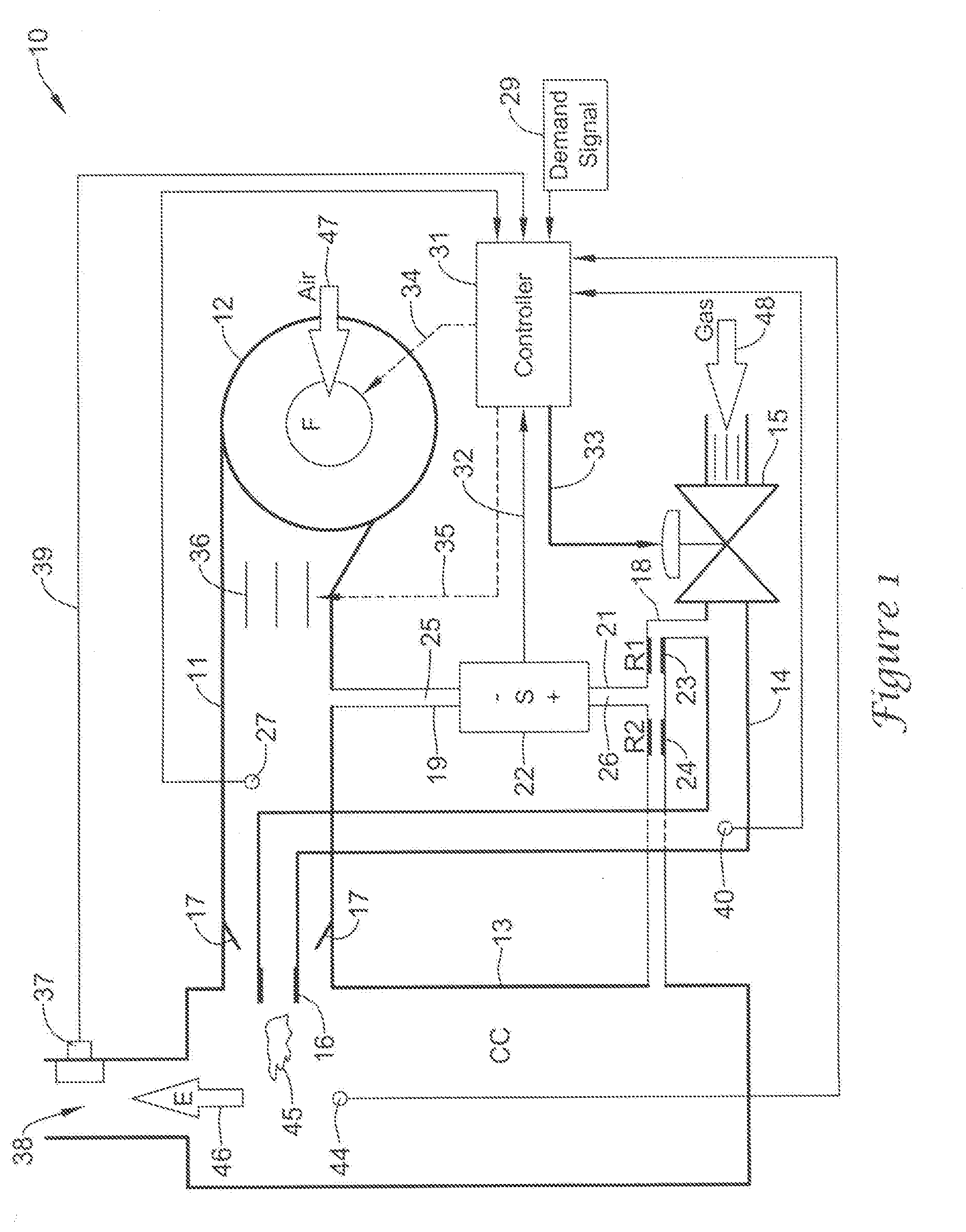
[0005] FIG. 1 is a diagram of a burner control system having a burner fuel and air mixture where a fuel parameter detected by the sensor is adjustable;
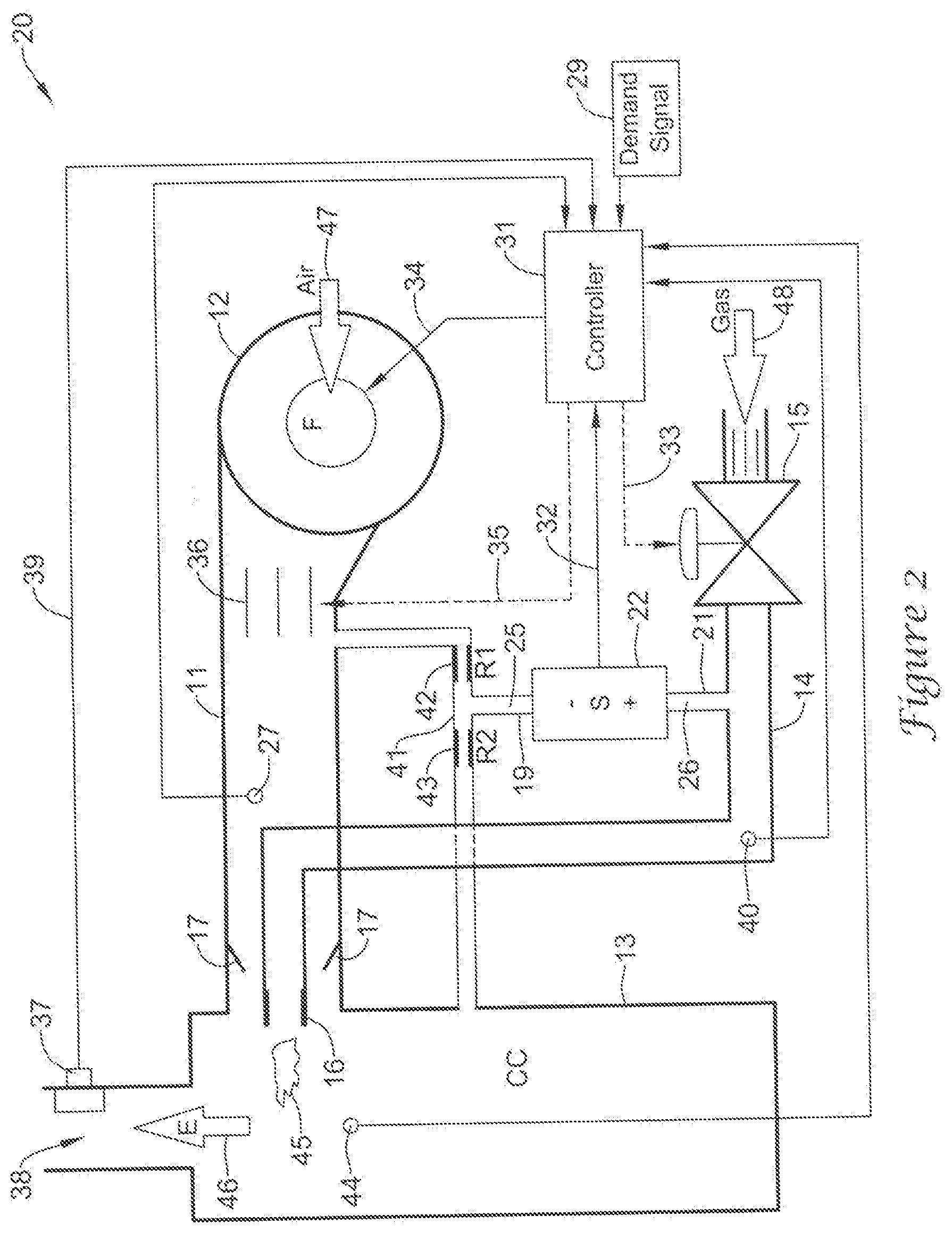
[0006] FIG. 2 is a diagram of a burner control system having a burner fuel and air mixture where an air parameter detected by the sensor is adjustable; and
[0007] FIG. 3 is a diagram of a burner control system having a burner fuel and air mixture where both the air and fuel parameters detected across the sensor are adjustable.
DESCRIPTION
[0008] Precise control of the fuel/air ratio may be one of the most important aspects of improving overall burner performance and efficiency. Related art control systems appear to lack the accuracy, flexibility, and function/feature sets to take full advantage of modern day burner performance or to advance burner designs to the next level. Two of the most common control systems for controlling burners in the related art may be the parallel positioning system and the pneumatic gas-air system. Both have drawbacks.
[0009] The parallel positioning system may rely on precisely positioning two actuators (one on a fuel control valve, one on an air damper) along a known, predefined curve. A drawback to this system may be that the actual flow of gas and air is not necessarily being measured directly and that certain shifts (i.e., temperature change, upstream pressure regulator drift, obstructed air supply, and so forth) might go undetected and uncompensated. An advantage of the parallel positioning system appears to be that it is flexible. This system may be used to control any fuel/air ratio profile (e.g., non-linear) and do it precisely.
[0010] The pneumatic gas-air system may utilize pneumatic feedback signals from gas, air, and optionally from the combustion chamber to control the amount of fuel. Since this system may rely on the fluid parameters of the gas and air directly, it is not necessarily sensitive to certain components' shifting (e.g., upstream pressure regulator drift or obstructed air supply). A disadvantage may be that only two points of the system might be calibrated and the fuel/air (F/A) curve would be a linear approximation to what the burner really needs between the two points. Additionally, this type of system may be sensitive to, for example, pressure surges due to ignition and pressure instabilities around the pressure pick-up detection points for Pgas (gas pressure), Pair (air pressure), and Pcc (combustion chamber pressure).
[0011] A present system may combine the strengths of the related-art systems and eliminate virtually all of their weaknesses. A control system may measure the ratio of the gas and air manifold parameters. The system may combine the measurement of gas and air in such a way that a single sensor can be used to measure both fluids. Optionally, a second sensor may be added for safety through redundancy or to expand the measurement range of the system. The sensor feedback signal may replace, or be used in conjunction with, the position feedback of a parallel positioning system. Since the sensor may be coupled directly to the air and fuel supply, the system is no longer necessarily sensitive to certain failure modes (e.g., regulator drift or obstructed air supply). The system may also have the desired flexibility. Any fuel air curve may be programmed and stored in the controller, despite non-linearity. In essence, this system may have virtually all of the flexibility of a parallel positioning system, and virtually all of the inherent safety of a pneumatic gas air system.
[0012] The present burner control arrangement may be a component of a heating system or a component of a heating, ventilation and air conditioning (HVAC) system.
[0013] Additional features may be added to the baseline system to make it even more useful to the end user. The gas and air flow may be trimmed by the controller to account for variability in the air and gas temperatures (i.e., densities). This may be achieved by measuring/estimating the temperature of the fluids and adjusting the flow restrictions of air and/or gas, accordingly. For example, by keeping the air flow constant and only changing the gas flow, the burner load may be kept constant. The system may be further trimmed based on the chemical composition of the flue gas. This may be achieved by measuring the byproducts (i.e., NOx, CO, HC, O2, and so forth) of combustion and adjusting the flow restrictions of air and/or gas accordingly. These two measures may be combined to eliminate nearly all of the tolerances from burner performance design, and should enable the end user of the system to run at optimum combustion across a turn-down ratio of the appliance.
[0014] In a standard burner configuration where a fan may be used to inject air into the burner under pressure, there may be a manifold for gas and a manifold for air coming into the burner. A bypass channel may be connected to the gas supply downstream of the control valve, but upstream of the burner orifice and then to the combustion chamber. In this bypass channel, there may be two orifices (at least one should be adjustable, but both can be adjustable for added flexibility of the system). These two orifices in series may form a pneumatic circuit commonly referred to as a pressure divider. The purpose of this circuit may be to reduce the gas pressure in the bypass channel from the manifold pressure to some pressure closer in value to the air pressure. Between the two orifices of the pressure divider circuit there may be a coupling between the gas bypass channel and the air supply channel. This may be referred to as a measurement channel. In the measurement channel, there may be mass flow, differential pressure or gauge pressure sensors. The sensors may measure the direction and magnitude of the flow through the measurement channel or of the differential pressure or gauge pressure, and provide feedback to the system's controller. The system constituting the sensor, measurement channel, bypass channel, pressure divider, fuel control valve, and controller may all be located in a single body, or may all be individual items, or may be made up of any combination. Optionally, a combustion sensor may be added to the control system for increased ease of system setup and for improved control accuracy during operation. A sensor may be placed in the flue of the combustion chamber or other appropriate location to observe byproducts of combustion.
[0015] Another feature may be an addition of temperature sensing to measure the air and gas temperatures. If this information is available to the system controller, then the temperature (density) affecting the system mass flow may be compensated out. The temperature compensation may or may not involve separate temperature sensors since many readily available pressure and flow sensors can have built-in temperature measurement used for compensating temperature drifts of the sensor and/or compensation of the system to account for temperature related changes in the working fluids.
[0016] To set up the present system in the field, the burner may be adjusted between minimum and maximum fire and the combustion byproducts may be observed (either manually or by the controller itself if it has its own combustion sensor). The air flow and gas flow may be adjusted to a desired amount at each point on the fuel/air curve between minimum and maximum fire, and the output of the sensor in the measurement channel may be recorded and stored by the controller. This process may be repeated until the entire fuel/air curve has been profiled and stored. Once the controller has this curve, it may adjust the air damper, fan or the fuel valve precisely based on a desired firing rate of the system and feedback from the sensor in the measurement channel.
[0017] One way that the system could work may be as follows: 1) A combustion sensor senses a byproduct concentration and sends a signal to the controller; 2) the controller recalculates the "predetermined magnitude of the parameter" based on the present and the desired byproduct concentrations; and the controller sends a signal to a control mechanism or mechanisms, adjusting fuel and/or air such that the parameter is driven to the new predetermined magnitude.
[0018] A system, where the temperature of both air and fuel is monitored, may work as follows: 1) A controller determines a difference between air and fuel temperatures; 2) The controller recalculates the "predetermined magnitude of the parameter" based on the temperature difference; and 3) The controller sends a signal to control mechanism(s), adjusting fuel and/or air such that the parameter is driven to the new predetermined magnitude.
[0019] FIG. 1 is a diagram of a burner control system 10 having a burner fuel and air mixture where the fuel pressure within or flow through the bypass channel 18 is adjustable. System 10 may have an air supply channel 11 for pumping air 47 with a fan 12 at one end of channel 11 into a chamber 13, such as a combustion chamber. At the other end of channel 11, there may be a baffle plate 17. Fuel 48, such as gas, may be injected downstream of baffle plate 28 into the airflow. Baffle plate 17 may be essential to make sure that the gas pressure is related to, for instance, the combustion chamber 13 pressure. This may assure that the gas flow goes down in case of a reduced air flow as a result of a flow blockage, e.g., in the flue.
[0020] Chamber 13 may be a volume where the one or more bypass channels terminate. Basically, the bypass channel or channels should terminate at a volume that has the same pressure as the termination points of the gas and air channels. Combustion chamber may be regarded herein as an illustrative example of chamber 13. A fuel channel 14 may be connected to a valve 15 at one end and connected at another end to an orifice 16. A measurement channel 19 may connect one end of a sensor 22 to air channel 11. A bypass channel 18 may have one end connected to fuel channel 14 and another end connected to combustion chamber 13. A measurement channel 21 may connect another end of sensor 22 to bypass channel 18. A resistive orifice 23 may be situated in bypass channel 18 between fuel channel 14 and measurement channel 21. Another resistive orifice 24 may be situated in bypass channel 18 between measurement channel 21 and combustion chamber 13. Orifices 23 and 24 may constitute a pressure divider circuit. Orifice 23 may be varied when tuning burner system 10. Orifice 24 may be fixed but could also or instead be variable. An orifice may be variable, for example, in size, shape and/or other property.
[0021] Sensor 22 may be one or more flow sensors, one or more pressure sensors, one or more differential pressure sensors, and/or a manifold of similar or different sensors. The present examples in FIGS. 1-3 may utilize a differential pressure sensor for illustrative purposes, though the differential sensor may be substituted with other kinds of sensors such as a flow sensor or gauge pressure sensors. For instance, if sensor 22 is a flow sensor, then a flow may go from a channel that would have had been indicated by the differential pressure sensor as the channel to have a higher pressure, to the other channel indicated to have the lower pressure as indicated by the differential pressure sensor if it were situated in lieu of the flow sensor.
[0022] When tuning the burner system 10 for operation with nominal settings of air flow in channel 11 and fuel 48 in channel 14, orifice 23, may be adjusted in size to, for example, equalize the pressures or adjust them to predefined magnitudes in measurement channels 19 and 21, which may be designated as pressures 25 and 26, respectively. As a result, for equalization between ports 19 and 20 as a matter of course, there should be no flow through a flow sensor 22 or there should be a zero pressure difference indicated by a differential pressure sensor 22. The differential pressure, flow rate, gauge pressures, or other parameter value does not necessarily need to be zero or reflect similar magnitudes of parameters relating to the air and fuel channels. There may be a deviation or offset from zero as a setpoint referred to for control of the air pressure, gas pressure, flow, or other parameter. A sensor or sensors indicating a parameter comparison relative to the air and fuel channels may allow for a lambda adjustment as a function of the burner load and/or air flow. In lieu of zero, there may be a predefined differential pressure, gauge pressures, flow, or other parameter relative to the burner load, fuel consumption, air usage, fuel air mixture, and/or the like.
[0023] After burner system 10 is in place after being tuned and operating, for instance, pressures 25 and 26 may become different resulting in an indication by sensor 22 that the pressures are different either by a flow or differential pressure indication. A signal 32 of the indication of pressures 25 and 26 or other parameters may go to a controller 31. In response to the difference in pressures 25 and 26, controller 31 may send a signal 33 to valve 15. Valve 15 may be motorized in that it may open or close incrementally according to signal 33. For example, if pressure 25 is greater than pressure 26, then via signals 32 and 33 to and from controller 31, respectively, valve 15 may open to increase the fuel pressure in channels 14 and 18, and thus pressure 26 until it is about equal to pressure 25 if that is the goal, or some predefined differential pressure. If pressure 25 is less than pressure 26, then via signals 32 and 33 to and from controller 31, respectively, valve 15 may close to decrease the fuel pressure in channels 14 and 18, and thus, for example, pressure 26 until it is about equal to pressure 25 if that is the goal, or some predefined differential pressure.
[0024] Controller 31 may be connected to fan 12 which may be varied in speed according to a signal 34 from controller 31 and thus vary flow of air 47 through channel 11. Changing speed of fan 12 may increase or decrease pressure 25 to make it equal to pressure 26, or result in a predetermined differential pressure between pressures 25 and 26, or some other parameter such as a flow rate, indicated by sensor 22 via signals 32 and 34 to and from controller 31, respectively.
[0025] Controller 31 may be connected to a motorized damper/louver 36 which may vary closure or opening of channel 11 to affect an amount of air flow through channel 11 according to a signal 35 from controller and thus vary the flow of air 47 through channel 11. Opening or closing damper/louver 36 may increase or decrease pressure 25 to make it equal to pressure 26, or to result in a predetermined differential pressure between pressures 25 and 26, as indicated by sensor 22 via signals 32 and 35 to and from controller 31, respectively.
[0026] Pressures 25 and 26 may also be equalized or differentiated to a predetermined value, with a combination of two or more kinds of control which incorporate control of valve 15, control of fan 12 and/or control of damper 36, via signals 33, 34 and 35, respectively, from controller 31 according to signal 32 from sensor 22. In a basic form, the present system pressures 25 and 26, or a flow rate between channels 19 and 21, may be adjusted to some value through control over the fuel 48, such as, for instance, gas.
[0027] Air temperature may be detected by a sensor 27 in air channel 11 and provided as a signal to controller 31 of systems 10, 20 and 30 of FIGS. 1, 2 and 3, respectively. Fuel temperature may be detected by sensor 40 in fuel channel 14 and provided as a signal to controller 31 of systems 10, 20 and 30. Instead, temperature sensing of the air 47 and/or fuel 48 may be a built-in part of primary control of the air and/or fuel, respectively. Controller 31 may compensate for densities of air 47 and fuel 48 in a fuel air ratio control. Sensors 27 and 40 may be a combination of temperature and pressure sensors.
[0028] A demand signal 29 may also go to controller 31 in systems 10, 20 and 30. Signal 29 may be regarded as a load control signal. A predefined pressure drop or offset, or flow rate across sensor 22 may be nearly instantaneously set by controller 31 through adjusting fuel valve 15 via line 33 and/or manipulating the air supply with a mechanism such as, for example, fan 12 or damper/louver 36 via lines 34 and 35, respectively, from controller 31. The pressure offset or flow across sensor 22 may be induced as a function of a demand signal 29. Demand signal 29 may effectively tell system 10, 20 or 30, what a firing rate should be, taking into account that a desired fuel air ratio may be different at different firing rates.
[0029] Any of systems 10, 20 and 30, may be used with virtually any control scheme such as controlling fuel 48 or air 47 only, controlling both fuel 48 and air 47, controlling both fuel and air with a combustion byproduct sensor to offset the system, controlling both the fuel and air with the combustion byproduct sensor 37, and so on. A combustion sensor 37 may be mounted at an exhaust port 38 of combustion chamber 13 to provide a signal 39, indicating information about byproducts in exhaust gases 46 emanating from a flame 45 at orifice 16 in combustion chamber 13 for systems 10, 20 and 30. Byproducts of combustion in the burner exhaust, temperatures of the gas and air, and/or flame quality may be monitored and adjusted with control of the fuel and air ratio for optimum combustion in the burner. A quality of flame 45 may be inferred from information about byproducts and/or other information such as parameters relative to pressure, temperature, flow and so forth. A specific flame quality sensor (not shown) may be incorporated. Signal 39 may go to controller 31, which can adjust pressures 25 and/or 26 or flow rate to change an amount of certain byproducts in exhaust gases 46. Sensor 37 may also or instead be a temperature sensor of exhaust gases 46. There may also be a sensor 44 situated in chamber 13 and connected to controller 31. Sensor 44 may be a pressure sensor, or a temperature sensor, or both a pressure and temperature sensor. A basic form of the system may incorporate a pressure divider on the fuel (restrictors 23 and 24) or air side (restrictors 42 and 43), sensor 22, valve 15 and controller 31 that takes signal 32 from sensor 22 and drives valve 15 with signal 33. The system does not necessarily control air 47 but rather the system may simply follow an air signal that the system is given. A flame sensor monitor may be added to the present system. The sensor may be a flame rod, optical sensor, and so on, that can monitor the combustion process and be used to offset the fuel air ratio.
[0030] FIG. 2 is a diagram of a burner control system 20 having a burner fuel and air mixture where the air pressure across the sensor is adjustable. System 20 may have some components similar to those of system 10 shown in FIG. 1. In system 20, port 21 of sensor 22 may be connected directly to fuel channel 14, since bypass channel 18 of system 10 is absent. Port 19 of sensor 22 may be connected to a bypass channel 41 that has a one end coupled to air channel 11 and another end coupled to combustion chamber 13. A restrictive orifice 42 may be situated in bypass channel 41 between the end of the bypass channel 41 coupled to air channel 11 and port 19 of sensor 22. A second resistive orifice 43 may be situated in bypass channel 41 between the coupling port 19 of sensor 22 and the end of bypass channel 41 that is coupled to combustion chamber 13. One or both orifices 42 and 43 may be variable, for instance, in size, shape and/or other property. Pressures 25 and 26 at ports 19 and 21, respectively, may be equalized initially by adjusting a passage size of one or both orifices 42 and 43, and then possibly be set to a predefined differential value of pressures 25 and 26 indicated by a pressure sensor 22, or a flow rate between ports 19 and 21 of a flow sensor 22. A variable passage may equal a bypass channel plus one or more restrictors. In operation further on in time, pressures 25 and 26 may be equalized or set to the predefined value by control of air flow in channel 11 by control of fan or air mover 12 with a signal 34 from controller 31 as guided by signal 32 indicating the differential pressure of pressures 25 and 26 or flow rate across sensor 22. Air flow in channel 11 may also be affected by damper or louver 36 with a signal 35 from controller 31 as guided by signal 32 from sensor 22. The differential of pressures 25 and 26, or flow rate between ports 19 and 21 of sensor 22, may also be affected by fuel flow in channel 14 as controlled by valve 15 with a signal 33 from controller 31 as guided by signal 32 from sensor 22. Control of the differential pressure or the flow rate may be effected by valve 15 control, air mover 12 control or damper/louver 36 control, or any combination of these controls. A basic system may utilize just the valve 15 control. Sensor 22 may detect or measure values or magnitudes of other parameters relative to channels 11 and 14.
[0031] FIG. 3 is a diagram of a burner system 30 having a burner fuel and air mixture where the air and fuel pressures or flow rate across sensor 22 may be adjustable. System 30 may have some components similar to those of systems 10 and 20 shown in FIGS. 1 and 2, respectively. Bypass channel 41 with restrictive orifices 42 and 43 may be coupled at one end to air channel 11 and coupled at the other end to combustion chamber 13. Port 19 of sensor 22 may be coupled to bypass channel 41 between orifices 42 and 43. Port 21 of sensor 22 may be coupled to bypass channel 18 between orifices 23 and 24. Bypass channel 18 with orifices 23 and 24 may be coupled at one end to fuel channel 14 and coupled at the other end to bypass channel 41 between orifice 43 and the end of channel 41 connected to combustion chamber 13. Instead of to channel 41, bypass channel 18 may have the other end coupled directly to chamber 13. At least one or more of orifices 23, 24, 42 and 43 may have an adjustable passage size, shape or other property. By adjusting the orifices in the bypass channels the gas flow may be adjusted in order to meet a desired lambda (excess air) setting of the application, and thus adjust the amplification factor between the air and gas pressures in the air channel 11 and fuel channel 14, or flow rate between channels 11 and 14 across sensor 22, respectively.
[0032] In operation further on in time, pressures 25 and 26 may be equalized or made to meet a desired differential pressure by control of air flow in channel 11 by control of fan or air mover 12 with a signal 34 from controller 31 as guided by signal 32 indicating the differential pressure of pressures 25 and 26 across sensor 22. Instead of the differential value of pressures 25 and 26, another parameter such as flow rate, may be measured across sensor 22. Air flow in channel 11 may also be affected by damper or louver 36 with a signal 35 from controller 31 as guided by signal 32 from sensor 22. The differential of pressures 25 and 26 or flow rate as indicated by sensor 22 may also be affected by fuel flow in channel 14 as controlled by valve 15 with a signal 33 from controller 31 as guided by signal 32 from sensor 22. Control of the differential pressure or flow rate may be effected by valve 15 control, air mover 12 control or damper/louver 36 control, or any combination of these controls. A measurement of gauge pressures at both ends of or across sensor 22, or flow rate may be measured through sensor 22 that is to provide a signal 32 to controller 31 and in turn the controller to provide the respective control signals for regulating air and fuel flow through the respective channels 11 and 14.
[0033] To recap, a burner control system for heating, ventilating and air conditioning (HVAC) may incorporate an air channel having an output coupled to a chamber, a fuel channel having an output coupled to the chamber, an air mover coupled to the air channel, a fuel valve coupled to an input of the fuel channel, a first bypass channel having a first end coupled to the air channel and having a second end coupled to the chamber, a second bypass channel having a first end coupled to the fuel channel and a second end coupled to the first bypass channel or the chamber, a sensor having a first port connected to the first bypass channel and having a second port connected to the second bypass channel, and a controller connected to the sensor. The sensor may detect a parameter between the first port of the sensor and the second port of the sensor. The sensor may provide a signal, indicating a magnitude of the parameter, to the controller. The controller may send a signal to a control mechanism to adjust an amount of fuel to the fuel channel and/or to adjust a quantity of air to the air channel, so as to cause the parameter to approach a predetermined magnitude for achieving a certain fuel air ratio of a fuel air mixture to the chamber. The parameter may be selected from a group consisting of a flow rate, differential pressure and gauge pressures.
[0034] There may also be a sensor, situated in the chamber and connected to the controller, for detecting a quality of a flame resulting from the fuel air mixture in the chamber. The quality of the flame may be used to achieve or adjust a ratio of the fuel air mixture.
[0035] The system may further incorporate a first restrictor orifice situated in the second bypass channel between the first end of the second bypass channel and the second port of the sensor, and a second restrictor orifice situated in the second bypass channel between the second port of the sensor and the second end of the second bypass channel.
[0036] The system may also further incorporate a third restrictor orifice situated in the first bypass channel between the first end of the first bypass channel and the first port of the sensor, and a fourth restrictor orifice situated in the first bypass channel between the first port of the sensor and second end of the second bypass channel coupled to the first bypass channel or the chamber.
[0037] One or more restrictor orifices may have a variable orifice size. The variable orifice size may be varied to make the parameter approach the predetermined magnitude.
[0038] The control mechanism may be the fuel valve that adjusts the amount of fuel to the fuel channel so as to cause the parameter to approach the predetermined magnitude. The control mechanism may be an air mover that adjusts the quantity of air to the air channel so as to cause the parameter to approach the predetermined magnitude.
[0039] The system may further incorporate a variable damper/louver situated in the air channel. The control mechanism may be the variable damper/louver that adjusts the quantity of air to the air channel so as to cause the parameter to approach the predetermined magnitude.
[0040] The sensor may be an item consisting of one or more sensors and is selected from a group consisting of one or more pressure sensors, differential pressure sensors, and flow sensors.
[0041] The system may further incorporate a combustion sensor situated at an exhaust port of the chamber. The combustion sensor may provide a signal, indicative of a concentration of one or more combustion byproducts, to the controller. The controller may calculate a predetermined magnitude of the parameter based on the concentration and desired concentration of the one or more combustion byproducts. The controller may send a signal to the control mechanism to adjust the amount of fuel to the fuel channel and/or to adjust the quantity of air to the air channel so as to drive the parameter to a new predetermined magnitude.
[0042] The system may further incorporate a temperature sensor situated in a fuel channel and/or air channel. The temperature sensor may provide a signal, indicative of a temperature of fuel and/or air, to the controller. The controller may calculate a predetermined magnitude of the parameter based on the temperature of the fuel and/or air. The controller may send a signal to the control mechanism to adjust the amount of fuel to the fuel channel and/or to adjust the quantity of air to the air channel so as to drive the parameter to a new predetermined magnitude.
[0043] Another burner control system may incorporate a chamber, an air channel having an output coupled to the chamber, a fuel channel having an output coupled to the chamber, an air mover coupled to the air channel, a fuel valve coupled to an input of the fuel channel, a bypass channel having a first end coupled to the fuel channel and having a second end coupled to the chamber, a sensor having a first port coupled to the air channel and having a second port coupled to the bypass channel, and a controller connected to the sensor and to the valve or the air mover.
[0044] A difference between a first parameter at the first port of the sensor and a second parameter at the second port of the sensor may be detected by the sensor.
[0045] The system may further incorporate one or more restrictors situated in the bypass channel. At least one restrictor of the one or more restrictors may have a variable flow restriction. A variable passage may incorporate a bypass channel and one or more restrictions. The variable passage may be tuned so that a difference of magnitudes of the first parameter and the second parameter approaches a magnitude to obtain a predetermined fuel air mixture during operation of the burner system.
[0046] If the difference of magnitudes of the first and second parameters is greater or less than a predetermined magnitude by a given delta of magnitude, a signal from the sensor to the controller may indicate the difference of the first and second parameters, and the controller may provide a signal to the valve to close or open the valve to decrease or increase fuel flow in the fuel channel or to the air mover to decrease or increase air flow and change the difference between the first and second parameters to approach the predetermined magnitude.
[0047] A predetermined magnitude of the difference between the first and second parameters may be needed to obtain a correct fuel air mixture. if the first parameter needs to be greater than the second parameter to approach the predetermined magnitude of the difference between the first and second parameters, then the controller may provide a signal to adjust the valve to change an amount of fuel entering the fuel channel or to adjust the air mover to change an amount of air entering the air channel which decreases the second parameter or increases the first parameter. If the second parameter needs to be greater than the first parameter to approach the predetermined magnitude of the difference between the first and second parameters, then the controller may provide a signal to the valve to change an amount of fuel entering the fuel channel or to adjust the air mover to change an amount of air entering the air channel which increases the second parameter or decreases the first parameter.
[0048] The following may be stated as an alternative to the previous paragraph. If the difference between the first and the second parameter needs to be increased to approach the predetermined magnitude of the difference between the first and second parameters, then the controller may provide a signal to adjust the valve to decrease an amount of fuel entering the fuel channel and/or to adjust the air mover to increase an amount of air entering the air channel which decreases the second parameter and/or increases the first parameter, respectively. If the difference between the first and the second parameter needs to be decreased to approach the predetermined magnitude of the difference between the first and second parameters, then the controller may provide a signal to adjust the valve to increase an amount of fuel entering the fuel channel and/or to adjust the air mover to decrease an amount of air entering the air channel which increases the second parameter and/or decreases the first parameter, respectively.
[0049] Still another burner system may incorporate an air channel having an output coupled to a combustion chamber, a fuel channel having an output coupled to the chamber, an air flow control mechanism coupled to the air channel, a fuel valve coupled to an input of the fuel channel, a bypass channel having a first end coupled to the air channel and having a second end coupled to the chamber, and a sensor having a first port coupled to the bypass channel and a second port coupled to the fuel channel.
[0050] The system may further incorporate a controller having an input connected to an output of the sensor. A difference between a first parameter at the first port of the sensor and a second parameter at the second port of the sensor may be detected by the sensor and indicated by the sensor on a signal to the controller. The system may still further incorporate one or more restrictors situated in the bypass channel. At least one restrictor of the one or more restrictors may have a variable flow restriction.
[0051] A predetermined magnitude of the difference between the first and second parameters may be needed to obtain a correct fuel air mixture. If the second parameter needs to be more than the first parameter to approach the predetermined magnitude of the difference between the first and second parameters, then the controller may provide a signal to the air flow control mechanism to adjust an amount of air going through the air channel or to the valve to adjust an amount of fuel going through the fuel channel which decreases the first parameter or increases the second parameter. If the first parameter needs to be greater than the second parameter to approach the predetermined magnitude of the difference between the first and second parameters, then the controller may provide a signal to the air flow control mechanism to adjust the amount of air going through the air channel or to the valve to adjust the amount of fuel going through the fuel channel which increases the first parameter or decreases the second parameter.
[0052] The system may further incorporate a second sensor connected to the controller and situated in the chamber. The second sensor may detect a quality of a flame in the chamber. The quality of the flame may be conveyed via a signal to the controller for calculating a fuel air mixture for optimizing the quality of the flame in the chamber. The fuel air mixture may be attained by signals from the controller to the air flow control mechanism and/or to the fuel valve. Optimizing the quality of the flame may incorporate reducing or increasing the byproducts in an exhaust of the chamber, increasing or decreasing an amount of heat per unit of fuel used, and/or achieving other beneficial results relative to energy, environment, efficiency, and/or the like.
[0053] In the present specification, some of the matter may be of a hypothetical or prophetic nature although stated in another manner or tense.
[0054] Although the present system and/or approach has been described with respect to at least one illustrative example, many variations and modifications will become apparent to those skilled in the art upon reading the specification. It is therefore the intention that the appended claims be interpreted as broadly as possible in view of the related art to include all such variations and modifications.
* * * * *
D00000
D00001
D00002
D00003
XML
uspto.report is an independent third-party trademark research tool that is not affiliated, endorsed, or sponsored by the United States Patent and Trademark Office (USPTO) or any other governmental organization. The information provided by uspto.report is based on publicly available data at the time of writing and is intended for informational purposes only.
While we strive to provide accurate and up-to-date information, we do not guarantee the accuracy, completeness, reliability, or suitability of the information displayed on this site. The use of this site is at your own risk. Any reliance you place on such information is therefore strictly at your own risk.
All official trademark data, including owner information, should be verified by visiting the official USPTO website at www.uspto.gov. This site is not intended to replace professional legal advice and should not be used as a substitute for consulting with a legal professional who is knowledgeable about trademark law.