Screw Compressor System for a Utility Vehicle
HEBRARD; Gilles ; et al.
U.S. patent application number 16/333495 was filed with the patent office on 2019-12-12 for screw compressor system for a utility vehicle. This patent application is currently assigned to KNORR-BREMSE SYSTEME FUR NUTZFAHRZEUGE GMBH. The applicant listed for this patent is KNORR-BREMSE SYSTEME FUR NUTZFAHRZEUGE GMBH. Invention is credited to Gilles HEBRARD, Jean-Baptiste MARESCOT, Joerg MELLAR, Thomas WEINHOLD.
| Application Number | 20190376517 16/333495 |
| Document ID | / |
| Family ID | 59982348 |
| Filed Date | 2019-12-12 |
| United States Patent Application | 20190376517 |
| Kind Code | A1 |
| HEBRARD; Gilles ; et al. | December 12, 2019 |
Screw Compressor System for a Utility Vehicle
Abstract
A screw compressor system for a utility vehicle has at least one screw compressor, at least one screw compressor drive, at least one temperature probe and at least one control and regulation unit. The control and/or regulation unit is connected to the screw compressor drive and to the temperature probe and is designed and configured such that it controls, in accordance with a temperature threshold signal obtained from the temperature probe, the screw compressor drive with respect to a rotational speed.
| Inventors: | HEBRARD; Gilles; (Muenchen, DE) ; MARESCOT; Jean-Baptiste; (Muenchen, DE) ; MELLAR; Joerg; (Muenchen, DE) ; WEINHOLD; Thomas; (Muenchen, DE) | ||||||||||
| Applicant: |
|
||||||||||
|---|---|---|---|---|---|---|---|---|---|---|---|
| Assignee: | KNORR-BREMSE SYSTEME FUR
NUTZFAHRZEUGE GMBH Muenchen DE |
||||||||||
| Family ID: | 59982348 | ||||||||||
| Appl. No.: | 16/333495 | ||||||||||
| Filed: | September 19, 2017 | ||||||||||
| PCT Filed: | September 19, 2017 | ||||||||||
| PCT NO: | PCT/EP2017/073581 | ||||||||||
| 371 Date: | June 5, 2019 |
| Current U.S. Class: | 1/1 |
| Current CPC Class: | F25B 49/022 20130101; F04C 2240/81 20130101; F04C 28/28 20130101; F25B 2700/21 20130101; F04C 28/00 20130101; F25B 2700/2105 20130101; F25B 2700/2115 20130101; F04C 2270/19 20130101; F25B 1/047 20130101; F25B 2600/0253 20130101; F04C 2270/05 20130101; Y02B 30/741 20130101; F25B 2500/26 20130101; F04C 18/16 20130101; F04C 28/08 20130101 |
| International Class: | F04C 18/16 20060101 F04C018/16 |
Foreign Application Data
| Date | Code | Application Number |
|---|---|---|
| Sep 21, 2016 | DE | 10 2016 011 508.4 |
Claims
1-9. (canceled)
10. A screw compressor system for a utility vehicle, comprising: at least one screw compressor; at least one screw compressor drive; at least one temperature sensor; and at least one open-loop and/or closed-loop control unit, wherein the open-loop and/or closed-loop control unit is connected to the screw compressor drive and to the temperature sensor, the open-loop and/or closed-loop control unit is configured so as to control the screw compressor drive with regard to a rotational speed thereof in a manner dependent on a temperature threshold value signal received from the temperature sensor.
11. The screw compressor system as claimed in claim 10, wherein the open-loop and/or closed-loop control unit is a constituent part of the screw compressor.
12. The screw compressor system as claimed in claim 10, wherein the open-loop and/or closed-loop control unit is a constituent part of an air treatment system of the utility vehicle.
13. The screw compressor system as claimed in claim 10, wherein the open-loop and/or closed-loop control unit is a constituent part of an engine or vehicle controller of the utility vehicle.
14. The screw compressor system as claimed in claim 10, wherein the open-loop and/or closed-loop control unit is a separate open-loop and/or closed-loop control unit.
15. The screw compressor system as claimed in claim 10, wherein the open-loop and/or closed-loop control unit is configured to deactivate the screw compressor drive upon receipt of a temperature threshold value signal that signals an overshooting of a predetermined temperature threshold value in the screw compressor.
16. The screw compressor system as claimed in claim 10, wherein the open-loop and/or closed-loop control unit is configured to permit an activation of the screw compressor drive only if said open-loop and/or closed-loop control unit receives a temperature threshold value signal that signals an undershooting of a predetermined temperature threshold value in the screw compressor.
17. The screw compressor system as claimed in claim 10, wherein the screw compressor system has no thermostat valve.
18. The screw compressor system as claimed in claim 17, wherein the screw compressor system has no heat exchanger for oil cooling.
19. The screw compressor system as claimed in claim 10, wherein the screw compressor system has no heat exchanger for oil cooling.
Description
BACKGROUND AND SUMMARY OF THE INVENTION
[0001] The present invention relates to a screw compressor system for a utility vehicle, having at least one screw compressor with at least one open-loop and/or closed-loop control unit for the open-loop and/or closed-loop drive control of the screw compressor.
[0002] Screw compressors for utility vehicles are already known from the prior art. Such screw compressors are used to provide the compressed air required for the brake system of the utility vehicle, for example.
[0003] In this context, in particular oil-filled compressors, in particular also screw compressors, are known, in the case of which it is necessary to regulate the oil temperature. This is generally realized by virtue of an external oil cooler being provided which is connected to the oil-filled compressor and to the oil circuit via a thermostat valve. Here, the oil cooler is a heat exchanger which has two mutually separate circuits, wherein the first circuit is provided for the hot liquid, that is to say the compressor oil, and the second circuit is provided for the cooling liquid. As cooling liquid, use may for example be made of air, water mixtures with an antifreeze, or another oil.
[0004] This oil cooler must then be connected to the compressor oil circuit by means of pipes or hoses, and the oil circuit must be safeguarded against leakage.
[0005] This external volume must furthermore be filled with oil, such that the total quantity of oil is also increased. The system inertia is thus increased. Furthermore, the oil cooler must be mechanically accommodated and fastened, either by means of brackets situated in the surroundings or by means of a separate bracket, which necessitates additional fastening means and also structural space.
[0006] U.S. Pat. No. 4,780,061 has already disclosed a screw compressor with an integrated oil cooling arrangement.
[0007] Furthermore, DE 37 17 493 A1 discloses a screw compressor installation which is arranged in a compact housing and which has an oil cooler on the electric motor of the screw compressor.
[0008] A generic screw compressor is already known for example from DE 10 2004 060 417 B4.
[0009] It is the object of the present invention to advantageously further develop a screw compressor system of the type mentioned in the introduction, in particular such that the open-loop and/or closed-loop drive control of the screw compressor can be made simpler and reliable.
[0010] This object is achieved according to the invention by a screw compressor system for a utility vehicle having at least one screw compressor, at least one screw compressor drive, at least one temperature sensor and at least one open-loop and/or closed-loop control unit. The open-loop and/or closed-loop control unit is connected to the screw compressor drive and to the temperature sensor, wherein the open-loop and/or closed-loop control unit is configured so as to control the screw compressor drive with regard to its rotational speed in a manner dependent on a temperature threshold value signal received from the temperature sensor.
[0011] The invention is based on the underlying concept that temperature management of the screw compressor system can be achieved by virtue of the screw compressor drive being correspondingly controlled in a manner dependent on the temperature in the screw compressor. The rotational speed of the screw compressor drive also significantly influences the temperature of the screw compressor. If a certain temperature is reached, then it is possible, through adaptation of the rotational speed of the screw compressor drive, for the temperature to be correspondingly increased or else lowered. In particular, provision may be made for the screw compressor system to be of relatively large design, such that, owing to the oil quantity present in the screw compressor, a certain inertia exists such that temperature changes occur. It is also conceivable for the screw compressor system to be one which is designed normally for part-load operation or operation at low load, and which does not need to be constantly operated at full load.
[0012] For example, provision may be made for the open-loop and/or closed-loop control unit to be a constituent part of the screw compressor system. In this way, a compact construction is formed, and it is not necessary to resort to external components.
[0013] It is however basically also conceivable for the open-loop and/or closed-loop control unit to be a constituent part of an air treatment system of the utility vehicle. Here, a corresponding controller is already provided, which can easily be jointly utilized.
[0014] It is also conceivable for the open-loop and/or closed-loop control unit to be a constituent part of an engine or vehicle controller of the utility vehicle. Here, too, it would be possible to resort to an existing component of the utility vehicle.
[0015] It is however basically also conceivable for the open-loop and/or closed-loop control unit to be in the form of a separate open-loop and/or closed-loop control unit. This permits, for example, easy installation and also an easy exchange or easy upgrades.
[0016] Furthermore, provision may be made for the open-loop and/or closed-loop control unit to be designed and configured to deactivate the screw compressor drive upon receipt of a temperature threshold value signal that signals an overshooting of a predetermined temperature threshold value in the screw compressor. In this way, a temperature reduction in the screw compressor can be achieved in a very short time in a simple and effective manner. In the absence of operation of the screw compressor, which is achieved by deactivation of the screw compressor drive, no further generation of heat occurs in the screw compressor, such that the latter can cool down.
[0017] It is furthermore conceivable for the open-loop and closed-loop control unit to be designed and configured to permit an activation of the screw compressor drive only if said open-loop and closed-loop control unit receives a temperature threshold value signal that signals an undershooting of a predetermined temperature threshold value in the screw compressor. The temperature threshold value signal that signals an undershooting of a predetermined temperature threshold value in the screw compressor may basically differ from a temperature threshold value signal which is received by the open-loop and/or closed-loop control unit by means of which a deactivation of the screw compressor drive is triggered. These temperature threshold value signals may however also be identical. By preventing a start or restart of the screw compressor in the presence of an excessively high temperature, simple but at the same time reliable open-loop and/or closed-loop control of the temperature in the screw compressor system or in the screw compressor is likewise made possible.
[0018] Provision may be made for the screw compressor system to have no thermostat valve. It is basically conceivable that, on the basis of the configuration of the open-loop and/or closed-loop control unit, the temperature management of the screw compressor can be implemented with such effectiveness that there is no need whatsoever for a heat-dependent activation of an oil cooling circuit, which commonly has a thermostat valve. This component of the screw compressor system can thus be omitted.
[0019] Provision may basically also be made for the screw compressor system to have no heat exchanger for oil cooling. Through the omission of this relatively expensive component, the construction of the screw compressor system can be simplified overall.
[0020] Further details and advantages of the invention will now be discussed in more detail on the basis of an exemplary embodiment illustrated in the drawings.
BRIEF DESCRIPTION OF THE DRAWINGS
[0021] FIG. 1 shows a schematic sectional drawing through a screw compressor according to the invention; and
[0022] FIG. 2 shows a schematic drawing of the screw compressor system according to the present invention.
DETAILED DESCRIPTION OF THE DRAWINGS
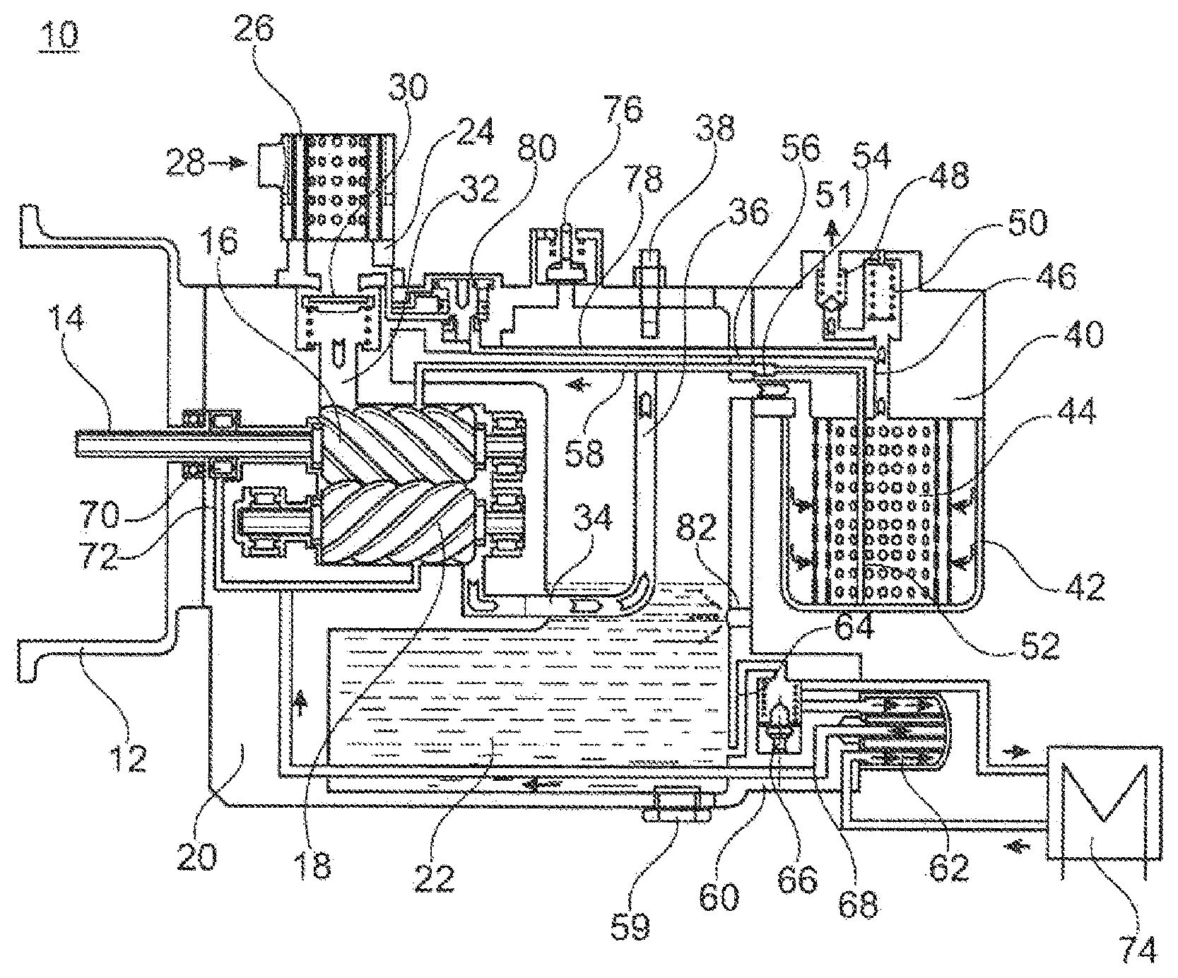
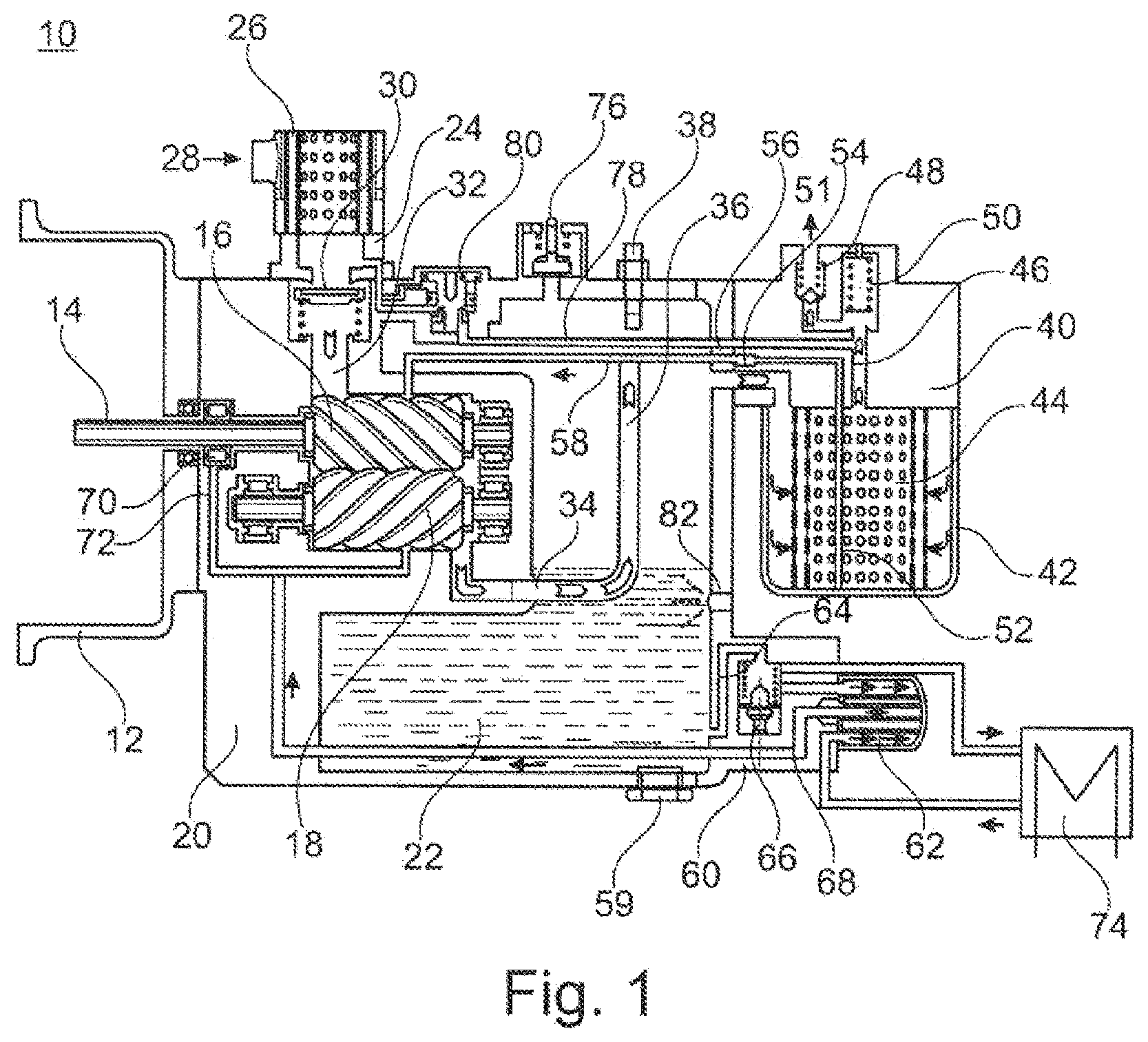
[0023] FIG. 1 shows, in a schematic sectional illustration, a screw compressor 10 in the context of an exemplary embodiment of the present invention.
[0024] The screw compressor 10 has a fastening flange 12 for the mechanical fastening of the screw compressor 10 to an electric motor (not shown in any more detail here).
[0025] What is shown, however, is the input shaft 14, by which the torque from the electric motor is transmitted to one of the two screws 16 and 18, specifically the screw 16.
[0026] The screw 18 meshes with the screw 16 and is driven by means of the latter.
[0027] The screw compressor 10 has a housing 20 in which the main components of the screw compressor 10 are accommodated.
[0028] The housing 20 is filled with oil 22.
[0029] At the air inlet side, an inlet connector 24 is provided on the housing 20 of the screw compressor 10. The inlet connector 24 is in this case designed such that an air filter 26 is arranged at said inlet connector. Furthermore, an air inlet 28 is provided radially on the air inlet connector 24.
[0030] In the region between the inlet connector 24 and the point at which the inlet connector 24 joins to the housing 20, there is provided a spring-loaded valve insert 30, which is designed here as an axial seal.
[0031] This valve insert 30 serves as a check valve.
[0032] Downstream of the valve insert 30, there is provided an air feed channel 32 which feeds the air to the two screws 16, 18.
[0033] At the outlet side of the two screws 16, 18, there is provided an air outlet pipe 34 with a riser line 36.
[0034] In the region of the end of the riser line 36, there is provided a temperature sensor 38 by means of which the oil temperature can be monitored.
[0035] Also provided in the air outlet region is a holder 40 for an air deoiling element 42.
[0036] In the assembled state, the holder 40 for the air deoiling element has the air deoiling element 42 in the region facing toward the base (as also shown in FIG. 1).
[0037] Also provided, in the interior of the air deoiling element 42, is a corresponding filter screen or known filter and oil separation devices 44, which will not be specified in any more detail.
[0038] In the central upper region in relation to the assembled and operationally ready state (that is to say as shown in FIG. 1), the holder for the air deoiling element 42 has an air outlet opening 46 which leads to a check valve 48 and a minimum pressure valve 50. The check valve 48 and the minimum pressure valve 50 may also be formed in one common combined valve.
[0039] The air outlet 51 is provided downstream of the check valve 48.
[0040] The air outlet 51 is generally connected to correspondingly known compressed-air consumers.
[0041] In order for the oil 22 that is situated and separated off in the air deoiling element 42 to be returned into the housing 20, a riser line 52 is provided which has a filter and check valve 54 at the outlet of the holder 40 for the air deoiling element 42 at the transition into the housing 20.
[0042] A nozzle 56 is provided, downstream of the filter and check valve 54, in a housing bore. The oil return line 58 leads back into approximately the central region of the screw 16 or of the screw 18 in order to feed oil 22 thereto again.
[0043] An oil drain screw 59 is provided in the base region, in the assembled state, of the housing 20. By means of the oil drain screw 59, a corresponding oil outflow opening can be opened, via which the oil 22 can be drained.
[0044] Also provided in the lower region of the housing 20 is the attachment piece 60 to which the oil filter 62 is fastened. Via an oil filter inlet channel 64, which is arranged in the housing 20, the oil 22 is conducted firstly to a thermostat valve 66.
[0045] Instead of the thermostat valve 66, it is possible for an open-loop and/or closed-loop control device to be provided by means of which the oil temperature of the oil 22 situated in the housing 20 can be monitored and set to a setpoint value.
[0046] Downstream of the thermostat valve 66, there is then the oil inlet of the oil filter 62, which, via a central return line 68, conducts the oil 22 back to the screw 18 or to the screw 16 again, or else to the oil-lubricated bearing 70 of the shaft 14. Also provided in the region of the bearing 70 is a nozzle 72, which is provided in the housing 20 in conjunction with the return line 68.
[0047] The cooler 74 is connected to the attachment piece 60, as will be discussed in more detail below in FIGS. 2 to 4.
[0048] In the upper region of the housing 20 (in relation to the assembled state), there is situated a safety valve 76, by means of which an excessively high pressure in the housing 20 can be dissipated.
[0049] Upstream of the minimum pressure valve 50, there is situated a bypass line 78, which leads to a relief valve 80. Via said relief valve 80, which is activated by means of a connection to the air feed 32, air can be returned into the region of the air inlet 28. In this region, there may be provided a ventilation valve (not shown in any more detail) and also a nozzle (diameter constriction of the feeding line).
[0050] Furthermore, approximately at the level of the line 34, an oil level sensor 82 may be provided in the outer wall of the housing 20. Said oil level sensor 82 may for example be an optical sensor, and may be designed and configured such that, on the basis of the sensor signal, it can be identified whether the oil level during operation is above the oil level sensor 82 or whether the oil level sensor 82 is exposed, and thus the oil level has correspondingly fallen.
[0051] In conjunction with this monitoring, it is also possible for an alarm unit to be provided which outputs or transmits a corresponding error message or warning message to the user of the system.
[0052] The function of the screw compressor 10 shown in FIG. 1 is as follows.
[0053] Air is fed via the air inlet 28 and passes via the check valve 30 to the screws 16, 18, where the air is compressed. The compressed air-oil mixture, which, having been compressed by a factor of between 5 and 16 downstream of the screws 16 and 18, rises through the outlet line 34 via the riser pipe 36, is blown directly onto the temperature sensor 38.
[0054] The air, which still partially carries oil particles, is then conducted via the holder 40 into the air deoiling element 42 and, if the corresponding minimum pressure is attained, passes into the air outlet line 51.
[0055] The oil 22 situated in the housing 20 is kept at operating temperature via the oil filter 62 and possibly via the heat exchanger 74.
[0056] If no cooling is necessary, the heat exchanger 74 is not used and is also not activated.
[0057] The corresponding activation is performed by means of the thermostat valve 66. After purification in the oil filter 62, oil is fed via the line 68 to the screw 18 or to the screw 16, or else to the bearing 70. The screw 16 or the screw 18 is supplied with oil 22 via the return line 52, 58, and the purification of the oil 22 takes place here in the air deoiling element 42.
[0058] By means of the electric motor (not shown in any more detail), which transmits its torque via the shaft 14 to the screw 16, which in turn meshes with the screw 18, the screws 16 and 18 of the screw compressor 10 are driven.
[0059] By means of the relief valve 80 (not shown in any more detail), it is ensured that the high pressure that prevails for example at the outlet side of the screws 16, 18 in the operational state cannot be enclosed in the region of the feed line 32, and that, instead, in particular during the start-up of the compressor, there is always a low inlet pressure, in particular atmospheric pressure, prevailing in the region of the feed line 32. Otherwise, upon a start-up of the compressor, a very high pressure would initially be generated at the outlet side of the screws 16 and 18, which would overload the drive motor.
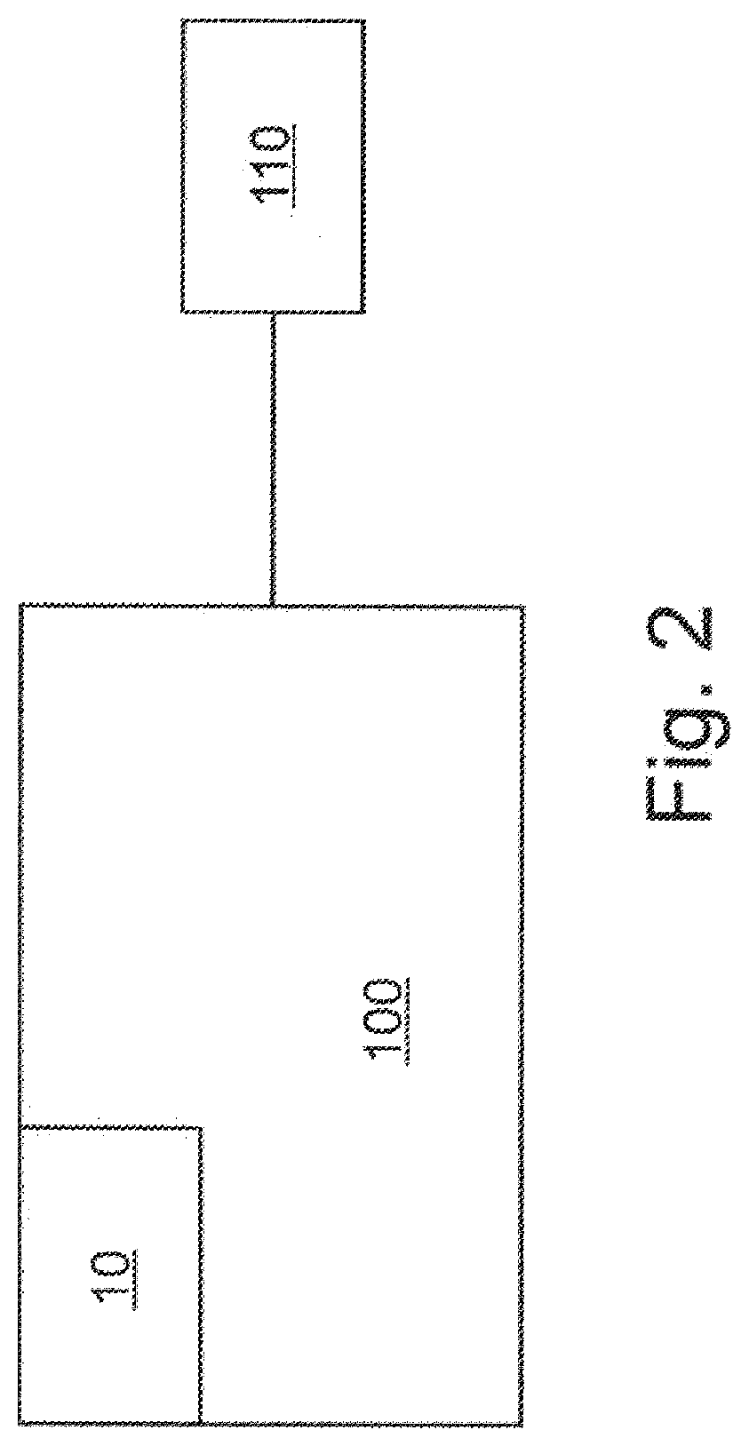
[0060] FIG. 2 shows, in a schematic illustration, a screw compressor system 100 according to the invention, having the screw compressor 10 shown in FIG. 1.
[0061] The screw compressor system 100 furthermore has an open-loop and/or closed-loop control unit 110, which is connected to the temperature sensor 38 and to the drive of the screws 16 and 18 of the screw compressor 10 (the electric motor, which is not shown in any more detail, and which transmits its torque to the input shaft 14).
[0062] Here, the open-loop and closed-loop control unit 110 is formed as a constituent part of the screw compressor 10.
[0063] Provision may however basically be made for the open-loop and closed-loop control unit 110 to be formed as a constituent part of an air treatment system (not shown in any more detail) of the utility vehicle, as a constituent part of an engine or vehicle controller of the utility vehicle, or as a separate open-loop and closed-loop control unit 110.
[0064] The open-loop and/or closed-loop control unit 110 is designed and configured so as to control the screw compressor drive with regard to its rotational speed in a manner dependent on a temperature threshold value signal received from the temperature sensor 38.
[0065] Here, provision is made in particular for the open-loop and closed-loop control unit 110 to deactivate the screw compressor drive upon receipt of a temperature threshold value signal that signals an overshooting of the predetermined temperature threshold value in the screw compressor 10.
[0066] A start-up of the screw compressor is possible again only when a temperature threshold value signal that signals an undershooting of a predetermined temperature threshold value in the screw compressor 10 is transmitted from the temperature sensor 38 to the open-loop and closed-loop control unit 110.
[0067] The temperature threshold value for the activation and deactivation of the screw compressor 10 is in this case preferably selected to be identical in order to permit simple implementation.
[0068] Provision may however basically also be made for different threshold values to be provided for this purpose.
[0069] The temperature threshold value may for example be selected to be approximately 10 to 30% above the normal working temperature.
[0070] By means of the embodiment shown in FIG. 2, it can be achieved that the screw compressor system 100, or the screw compressor 10, no longer needs to have a thermostat valve 66, and also no longer needs to have a heat exchanger 74.
LIST OF REFERENCE DESIGNATIONS
[0071] 10 Screw compressor [0072] 12 Fastening flange [0073] 14 Input shaft [0074] 16 Screws [0075] 18 Screws [0076] 20 Housing [0077] 22 Oil [0078] 24 Inlet connector [0079] 26 Air filter [0080] 28 Air inlet [0081] 30 Valve insert [0082] 32 Air feed channel [0083] 34 Air outlet pipe [0084] 36 Riser line [0085] 38 Temperature sensor [0086] 40 Holder for an air deoiling element [0087] 42 Air deoiling element [0088] 44 Filter screen or known filter or oil separation devices [0089] 46 Air outlet opening [0090] 48 Check valve [0091] 50 Minimum pressure valve [0092] 51 Air outlet [0093] 52 Riser line [0094] 54 Filter and check valve [0095] 56 Nozzle [0096] 58 Oil return line [0097] 59 Oil drain screw [0098] 60 Attachment piece [0099] 60a Outer ring [0100] 60b Inner ring [0101] 62 Oil filter [0102] 64 Oil filter inlet channel [0103] 66 Thermostat valve [0104] 68 Return line [0105] 70 Bearing [0106] 72 Nozzle [0107] 74 Cooler, heat exchanger [0108] 76 Safety valve [0109] 78 Bypass line [0110] 80 Relief valve [0111] 82 Oil level sensor [0112] 100 Screw compressor system [0113] 110 Open-loop and/or closed-loop control unit
* * * * *
D00000
D00001
D00002
XML
uspto.report is an independent third-party trademark research tool that is not affiliated, endorsed, or sponsored by the United States Patent and Trademark Office (USPTO) or any other governmental organization. The information provided by uspto.report is based on publicly available data at the time of writing and is intended for informational purposes only.
While we strive to provide accurate and up-to-date information, we do not guarantee the accuracy, completeness, reliability, or suitability of the information displayed on this site. The use of this site is at your own risk. Any reliance you place on such information is therefore strictly at your own risk.
All official trademark data, including owner information, should be verified by visiting the official USPTO website at www.uspto.gov. This site is not intended to replace professional legal advice and should not be used as a substitute for consulting with a legal professional who is knowledgeable about trademark law.