Electric Oil Pump
KOBAYASHI; Yoshiyuki ; et al.
U.S. patent application number 16/486175 was filed with the patent office on 2019-12-12 for electric oil pump. The applicant listed for this patent is Nidec Tosok Corporation. Invention is credited to Takamitsu ETO, Hirotaka KANAMONO, Shigehiro KATAOKA, Yoshiyuki KOBAYASHI.
| Application Number | 20190376511 16/486175 |
| Document ID | / |
| Family ID | 63370088 |
| Filed Date | 2019-12-12 |


View All Diagrams
| United States Patent Application | 20190376511 |
| Kind Code | A1 |
| KOBAYASHI; Yoshiyuki ; et al. | December 12, 2019 |
ELECTRIC OIL PUMP
Abstract
An electric oil pump includes a motor, a pump, and a motor driver. The pump includes a pump rotor attached to the shaft, a pump body, and a pump cover. A motor driver includes an inverter circuit that controls driving of a motor and an inverter cover. The inverter circuit is in thermal contact with the pump cover.
| Inventors: | KOBAYASHI; Yoshiyuki; (Zama-shi, JP) ; ETO; Takamitsu; (Zama-shi, JP) ; KATAOKA; Shigehiro; (Zama-shi, JP) ; KANAMONO; Hirotaka; (Zama-shi, JP) | ||||||||||
| Applicant: |
|
||||||||||
|---|---|---|---|---|---|---|---|---|---|---|---|
| Family ID: | 63370088 | ||||||||||
| Appl. No.: | 16/486175 | ||||||||||
| Filed: | February 23, 2018 | ||||||||||
| PCT Filed: | February 23, 2018 | ||||||||||
| PCT NO: | PCT/JP2018/006647 | ||||||||||
| 371 Date: | August 15, 2019 |
| Current U.S. Class: | 1/1 |
| Current CPC Class: | F04C 2240/50 20130101; F04C 29/047 20130101; F04C 15/0096 20130101; F04C 2240/40 20130101; F04C 2240/60 20130101; F04C 11/008 20130101; H02K 11/33 20160101; F04C 2240/808 20130101; F04C 15/0088 20130101; F04C 2210/206 20130101; F04C 2/102 20130101; H02K 7/14 20130101; F04C 2240/30 20130101 |
| International Class: | F04C 15/00 20060101 F04C015/00 |
Foreign Application Data
| Date | Code | Application Number |
|---|---|---|
| Mar 3, 2017 | JP | 2017-040629 |
Claims
1-15. (canceled)
16: An electric oil pump comprising: a motor including a shaft rotatable with respect to a central axis extending in an axial direction; a pump that is positioned on a first side of the motor in the axial direction, is driven by the shaft extending from the motor, and discharges oil; and a motor driver that is positioned on the first side of the motor in the axial direction via the pump and drives the motor; wherein the motor includes: a rotor that is rotatable around the shaft; a stator disposed on a side outward from the rotor in a radial direction; and a housing that houses the rotor and the stator; the pump includes: a pump rotor attached to the shaft; a pump body including a recess that houses the pump rotor and includes a side wall surface and a bottom surface positioned on the second side of the motor in the axial direction, and an opening on the first side of the motor in the axial direction; and a pump cover that closes the opening; the motor driver includes: an inverter circuit that controls driving of the motor; and an inverter cover that covers the inverter circuit; wherein the inverter circuit is in thermal contact with the pump cover.
17: The electric oil pump according to claim 16, wherein an inlet to take in the oil is provided at a position on the pump cover, and an outlet to discharge the oil is provided in the pump cover on a side opposite to the position of the inlet with respect to the center axis.
18: The electric oil pump according to claim 16, wherein an inlet to take in the oil is provided at a position on the pump cover, a delivery port that communicates with the motor is provided in the bottom surface of the recess on a side opposite to the position of the inlet with respect to the center axis, and an outlet to discharge the oil is provided on a bottom surface or a side surface of the housing.
19: The electric oil pump according to claim 16, wherein an inlet to take in the oil is provided at a position on the pump body, and an outlet to discharge the oil is provided in the pump body on a side opposite to the position of the inlet with respect to the center axis.
20: The electric oil pump according to claim 16, wherein the pump cover is in thermal contact with the inverter circuit via a heat dissipation body.
21: The electric oil pump according to claim 17, wherein the inverter circuit is disposed on an inlet side of the central axis.
22: The electric oil pump according to claim 16, wherein the inverter circuit includes a circuit board and a heater, and the heater is in thermal contact with the inverter cover.
23: The electric oil pump according to claim 22, wherein the heater of the inverter circuit is in thermal contact with the inverter cover via a heat dissipation body.
24: The electric oil pump according to claim 22, wherein the heater of the inverter circuit is disposed on an inlet side of the central axis.
25: The electric oil pump according to claim 22, wherein the heater of the inverter circuit includes a field effect transistor.
26: The electric oil pump according to claim 22, wherein the circuit board of the inverter circuit is a copper-inlaid substrate.
27: The electric oil pump according to claim 22, wherein the circuit board of the inverter circuit includes a plurality of substrates.
28: The electric oil pump according to claim 16, wherein the pump body includes a bearing.
29: The electric oil pump according to claim 28, wherein the bearing includes a ball bearing.
30: The electric oil pump according to claim 28, wherein the bearing includes a sliding bearing.
Description
CROSS REFERENCE TO RELATED APPLICATIONS
[0001] This is a U.S. national stage of PCT Application No. PCT/JP2018/006647, filed on Feb. 23, 2018, and priority under 35 U.S.C. .sctn. 119(a) and 35 U.S.C. .sctn. 365(b) is claimed from Japanese Application No. 2017-040629, filed Mar. 3, 2017; the entire disclosures of each application are hereby incorporated herein by reference.
1. FIELD OF THE INVENTION
[0002] The present invention relates to an electric oil pump.
2. BACKGROUND
[0003] Continuously variable transmissions (CVT), dual clutch transmissions (DCT), and the like have been known as transmissions for automobiles and the like in recent years. Various forms of transmissions have been discussed to improve fuel efficiency.
[0004] In addition, transmissions are required to have a function of supplying oil by using a motor at the time of idle reduction or the like, and an electric oil pump having an inverter circuit, a motor, and a pump for realizing this function is required.
[0005] For example, Japanese Unexamined Patent Application Publication No. 2015-175291 discloses an electric oil pump with a structure in which a part of a pump cover in which an inverter circuit is housed serves as a part of a transmission case.
[0006] However, since the electric oil pump disclosed in Japanese Unexamined Patent Application Publication No. 2015-175291 has a pump cover also serving as a part of the transmission case, the structure of the electric oil pump is limited by the structure of the transmission. Therefore, it is not possible to use the electric oil pump with a structure including an inverter circuit, a motor, and a pump generally in various transmissions.
[0007] In addition, in a case in which an electric oil pump is required to exhibit higher output performance in terms of responsiveness and the like, a quantity of heat from elements used in the inverter circuit increases, and thus the inverter circuit needs to be efficiently cooled.
SUMMARY
[0008] Example embodiments of the present disclosure provide electric oil pumps each of which is usable for various transmissions and achieves efficiently cooling of an inverter circuit.
[0009] An electric oil pump according to an example embodiment of the present disclosure includes a motor including a shaft rotatable with respect to a central axis extending in an axial direction, a pump that is located on a first side of the motor in the axial direction, driven by the shaft extending from the motor, and discharges oil, and a motor driver that is positioned on a second side of the motor in the axial direction via the pump and drives the motor, wherein the motor includes a rotor that is rotatable around the shaft, a stator disposed on a side outward from the rotor in a radial direction, and a housing that houses the rotor and the stator, wherein the pump includes a pump rotor attached to the shaft, a pump body including a recess that houses the pump rotor and includes a side wall surface and a bottom surface positioned on the second side of the motor in the axial direction, and an opening on the first side of the motor in the axial direction, and a pump cover that closes the opening, the motor driver includes an inverter circuit that controls driving of the motor, and an inverter cover that covers the inverter circuit, and the inverter circuit is in thermal contact with the pump cover.
[0010] According to example embodiments of the present disclosure, it is possible to provide electric oil pumps each usable for various transmissions and efficiently cooling an inverter circuit.
[0011] The above and other elements, features, steps, characteristics and advantages of the present disclosure will become more apparent from the following detailed description of the example embodiments with reference to the attached drawings.
BRIEF DESCRIPTION OF THE DRAWINGS
[0012] FIG. 1 illustrates a cross-sectional diagram of an electric oil pump according to a first example embodiment of the present disclosure.
[0013] FIG. 2 illustrates a cross-sectional diagram of a first modified example of a motor drive unit of the present disclosure.
[0014] FIG. 3 illustrates a cross-sectional diagram of a second modified example of a motor drive unit of the present disclosure.
[0015] FIG. 4 illustrates a cross-sectional diagram of a third modified example of a motor drive unit of the present disclosure.
[0016] FIG. 5 illustrates a cross-sectional diagram of a fourth modified example of a motor drive unit of the present disclosure.
[0017] FIG. 6 illustrates a cross-sectional diagram of a fifth modified example of a motor drive unit of the present disclosure.
[0018] FIG. 7 illustrates a cross-sectional diagram of a sixth modified example of a motor drive unit of the present disclosure.
[0019] FIG. 8 illustrates a cross-sectional diagram of a seventh modified example of a motor drive unit of the present disclosure.
[0020] FIG. 9 illustrates a cross-sectional diagram of an electric oil pump according to a second example embodiment of the present disclosure.
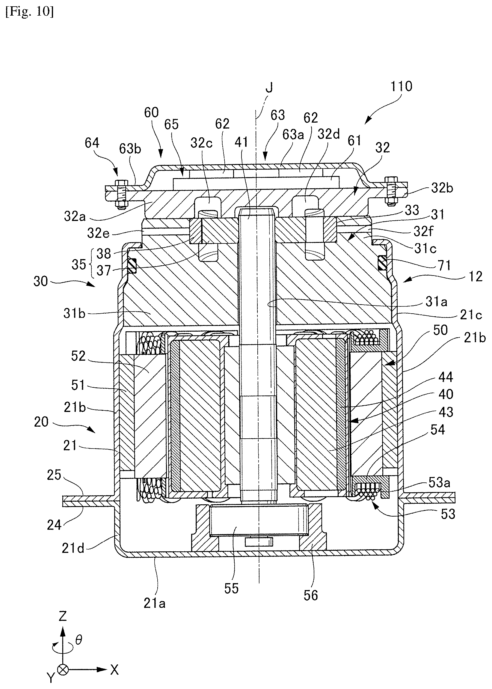
[0021] FIG. 10 illustrates a cross-sectional diagram of an electric oil pump according to a third example embodiment of the present disclosure.
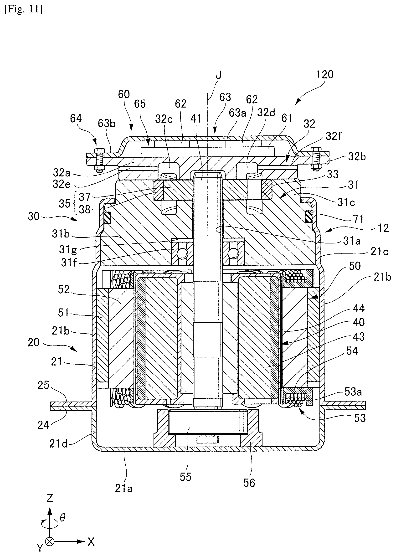
[0022] FIG. 11 illustrates a cross-sectional diagram of an electric oil pump according to a fourth example embodiment of the present disclosure.
DETAILED DESCRIPTION
[0023] Electric oil pumps according to example embodiments of the present disclosure will be described below with reference to the drawings. In addition, scales, numerical values, and the like of each structure may differ from those of actual structures in the following drawings in order to facilitate understanding of respective components.
[0024] In addition, an XYZ coordinate system is appropriately shown in the drawings as a three-dimensional orthogonal coordinate system. In an XYZ coordinate system, a Z axis direction is parallel to the axial direction of the central axis J shown in FIG. 1. An X axis direction is parallel to a direction in which a top board 63a of an inverter cover 63 shown in FIG. 1 extends, that is, the left-right direction of FIG. 1. A Y axis direction is orthogonal to both the X axis direction and the Z axis direction.
[0025] Furthermore, in the following description, a positive side of the Z axis direction (+Z side) will be referred to as a "front side," and a negative side of the Z axis direction (-Z side) will be referred to as a "rear side." Note that the rear side and the front side are merely names used for description, and do not restrict actual positional relationships and directions. In addition, a direction parallel to the central axis J (Z axis direction) will be referred to simply as an "axial direction," a radial direction with respect to the central axis J will be referred to simply as a "radial direction," and a circumferential direction with respect to the central axis J, that is, a direction around the central axis J (.theta. direction), will be referred to simply as a "circumferential direction", unless specified otherwise.
[0026] Note that, in the present specification, the phrase "in thermal contact with" includes not only a case in which target members are in direct contact with each other but also a case in which members sandwich a member relating to heat conduction therebetween. In addition, in the present specification, the phrase "extending in the axial direction" includes extending in a direction inclining from the axial direction by an angle in a range less than 45.degree., as well as extending exactly in the axial direction (Z axis direction). In addition, in the present specification, the phrase "extending in the radial direction" includes extending in a direction inclining from the radial direction by an angle in a range less than 45.degree., as well as extending exactly in the radial direction, that is, a direction perpendicular to the axial direction (Z axis direction).
First Example Embodiment
<Overall Configuration>
[0027] FIG. 1 illustrates a cross-sectional diagram of an electric oil pump according to the present example embodiment.
[0028] The electric oil pump 10 according to the present example embodiment has a motor unit 20, a pump unit 30, and a motor drive unit 60. The motor unit 20, the pump unit 30, and the motor drive unit 60 are provided in a row in the axial direction.
[0029] The motor unit 20 has a shaft 41 that extends in the axial direction and is supported to be rotatable around the central axis J and causes the shaft 41 to rotate and thereby drives the pump. The pump unit 30 is positioned on the front side (+Z side) of the motor unit 20, is driven by the motor unit 20 via the shaft 41, and discharges oil. The motor drive unit 60 is positioned on the front side (+Z side) of the pump unit 30 and controls driving of the motor unit 20.
[0030] Each of constituent members will be described below in detail.
<Motor Unit 20>
[0031] The motor unit 20 has a housing 21, a rotor 40, a shaft 41, a stator 50, and a bearing 55, as illustrated in FIG. 1.
[0032] The motor unit 20 is, for example, an inner rotor-type motor in which the rotor 40 is fixed to an outer circumferential surface of the shaft 41 and the stator 50 is positioned outward from the rotor 40 in the radial direction. In addition, the bearing 55 is disposed at an end of the shaft 41 on the rear side (-Z side) in the axial direction and supports the shaft 41 to be rotatable.
(Housing 21)
[0033] The housing 21 has a bottomed thin cylindrical shape as illustrated in FIG. 1 and has a bottom part 21a, a stator holding part 21b, a pump body holding part 21c, a side wall part 21d, and flange parts 24 and 25. The bottom part 21a constitute the bottom portion, and the stator holding part 21b, the pump body holding part 21c, and the side wall part 21d constitute a cylindrical side wall surface with respect to the central axis J. In the present example embodiment, an inner diameter of the stator holding part 21b is larger than that of the pump body holding part 21c. An outer surface of the stator 50, that is, an outer surface of a core back part 51 which will be described below, is fitted to an inner surface of the stator holding part 21b. Accordingly, the stator 50 is housed in the housing 21. The flange part 24 spreads outward from an end part of the side wall part 21d on the front side (+Z side) in the radial direction. On the other hand, the flange part 25 spreads outward from an end part of the stator holding part 21b on the rear side (-Z side) in the radial direction. The flange parts 24 and 25 face each other and are fastened by a fastening means, which is not illustrated. Accordingly, the motor unit 20 and the pump unit 30 are sealed and fixed inside the housing 21.
[0034] For a material of the housing 21, for example, a zinc-aluminum-magnesium-based alloy or the like can be used, and specifically, steel sheets and strips plated with a molten zinc-aluminum-magnesium alloy can be used. In addition, a bearing holding part 56 for holding the bearing 55 is provided in the bottom part 21a.
(Rotor 40)
[0035] The rotor 40 has a rotor core 43 and a rotor magnet 44. The rotor core 43 surrounds the shaft 41 in the direction around the axis (in the 0 direction) and is fixed to the shaft 41. The rotor magnet 44 is fixed to an outer surface of the rotor core 43 in a direction around the axis (in the 0 direction). The rotor core 43 and the rotor magnet 44 rotate along with the shaft 41.
(Stator 50)
[0036] The stator 50 surrounds the rotor 40 in a direction around the axis (in the 0 direction) and causes the rotor 40 to rotate around the central axis J. The stator 50 has the core back part 51, tooth parts 52, a coil 53, and a bobbin (insulator) 54.
[0037] A shape of the core back part 51 is a cylindrical shape concentric with the shaft 41. The tooth parts 52 extend from an inner surface of the core back part 51 toward the shaft 41. A plurality of tooth parts 52 are provided and are disposed on the inner surface of the core back part 51 in a circumferential direction at equal intervals. The coil 53 is provided around the bobbing (insulator) 54 and a conductive wire 53a is wound therearound. The bobbin (insulator) 54 is installed in each of the tooth parts 52.
(Bearing 55)
[0038] The bearing 55 is disposed on the rear side (-Z side) of the rotor 40 and the stator 50 and is held by the bearing holding part 56. The bearing 55 supports the shaft 41. A shape, a structure, and the like of the bearing 55 are not particularly limited, and any known bearing can also be used.
<Pump Unit 30>
[0039] The pump unit 30 is provided on one side of the motor unit 20 in the axial direction, specifically on the front side (+Z side). The pump unit 30 has the same rotation axis as the motor unit 20 and is driven by the motor unit 20 via the shaft 41. The pump unit 30 has a positive displacement pump from which oil is pressure-fed by enlarging and reducing the volume of a tightly sealed space (an oil chamber). A trochoid pump, for example, may be used as the positive displacement pump. The pump unit 30 has a pump body 31, a pump cover 32, and a pump rotor 35. Note that a combination of the pump body 31 and the pump cover 32 will also be referred to as a pump case hereinafter.
(Pump Body 31)
[0040] The pump body 31 is positioned on the front side (+Z side) of the motor unit 20. The pump body 31 has a main pump body 31b, a through hole 31a penetrating through the inside of the main pump body 31b along the axial direction of the central axis J, and a projection part 31c projecting in a cylindrical shape from the main pump body 31b on the front side (+Z side). An inner diameter of the projection part 31c is larger than that of the through hole 31a. The projection part 31c and the main pump body 31b constitute a recess 33 that is open on the side toward the pump cover 32. The through hole 31a is open toward the motor unit 20 on the rear side (-Z side) and is open at the recess 33 on the front side (+Z side). The through hole 31a functions as a bearing member that rotatably supports the shaft 41 inserted thereinto. The recess 33 houses the pump rotor 35 and functions as a pump chamber (which will also be referred to as a pump chamber 33 hereinafter).
[0041] The pump body 31 is fixed inside the pump body holding part 21c on the front side (+Z side) of the motor unit 20. An O-ring 71 is provided between an outer circumferential surface of the main pump body 31b and an inner circumferential surface of the pump body holding part 21c in the radial direction. Accordingly, the gap between the outer circumferential surface of the pump body 31 and the inner circumferential surface of the housing 21 in the radial direction is sealed.
[0042] Cast iron or the like, for example, can be used as a material of the pump body 31.
(Pump Rotor 35)
[0043] The pump rotor 35 is attached to an end of the shaft 41 on the front side (+Z side) and is housed in the pump chamber 33. The pump rotor 35 has an inner rotor 37 attached to the shaft 41 and an outer rotor 38 surrounding the outer side of the inner rotor 37 in the radial direction.
[0044] The inner rotor 37 is an annular gear having teeth on the outer surface thereof in the radial direction. The inner rotor 37 is fixed to the shaft 41 by press-fitting an end of the shaft 41 on the front side (+Z side) thereinto. The inner rotor 37 rotates in the direction around the axis (in the .theta. direction) along with the shaft 41.
[0045] The outer rotor 38 surrounds the outer side of the inner rotor 37 in the radial direction and is an annular gear having teeth on an inner surface in the radial direction. The outer rotor 38 is rotatably housed in the pump chamber 33. The outer rotor 38 has an inner housing chamber (not illustrated) that houses the inner rotor 37, the inner housing chamber being formed, for example, in a star shape. The number of internal teeth of the outer rotor 38 is greater than the number of external teeth of the inner rotor 37.
[0046] The inner rotor 37 and the outer rotor 38 mesh with each other, and when the inner rotor 37 rotates due to the shaft 41, the outer rotor 38 rotates according to the rotation of the inner rotor 37. Since the inner rotor 37 and the outer rotor 38 rotate, the volume of the space generated between the inner rotor 37 and the outer rotor 38 changes depending on their rotation position. The pump rotor 35 utilizes the change in the volume to take-in oil from an inlet port 32c, which will be described below, applies a pressure to the received oil, and discharges the oil to an outlet port 32d. In the present example embodiment, a region in the space generated between the inner rotor 37 and the outer rotor 38 in which a volume increases (i.e., oil is taken-in) is called a negatively pressurized region.
(Pump Cover 32)
[0047] The pump cover 32 is attached on the front side (+Z side) of the pump body 31. The pump cover 32 has a main pump cover 32a, a flange part 32b, the inlet port 32c, the outlet port 32d, an inlet 32e, and an outlet 32f.
[0048] The pump cover 32 is generally formed of a metal such as an aluminum alloy and has a large heat capacity and surface area, and thus the pump cover has a high heat radiating effect. In addition, since oil having a temperature equal to or lower than a certain temperature (e.g., 120.degree. C.) flows inside the pump cover 32, an increase in temperature of the pump cover 32 is mitigated.
[0049] The main pump cover 32a has a disk shape extending in the radial direction. The main pump cover 32a closes an opening of the recess 33 on the front side (+Z side). The flange part 32b extends from an outer edge on the front side (+Z side) of the main pump cover 32a in the radial direction. An outer diameter of the pump cover 32 is greater than that of the projection part 31c of the pump body 31 since the pump cover 32 has the flange part 32b.
[0050] The inlet port 32c is a crescent-shaped groove when viewed from the pump rotor 35 to the front side (+Z side). The inlet port 32c communicates with the pump rotor 35 on a degree that increases with the increasing volume of the space generated between the inner rotor 37 and the outer rotor 38. Likewise, the outlet port 32d also is a crescent-shaped groove when viewed from the pump rotor 35 to the front side (+Z side). The outlet port 32d communicates with the pump rotor 35 on a degree that decreases with decreasing volume of the space formed between the inner rotor 37 and the outer rotor 38.
[0051] The inlet 32e extends from the inlet port 32c toward a -X side (to the left side of the drawing) within the main pump cover 32a and communicates with the outside. On the other hand, the outlet 32f extends from the outlet port 32d toward an X side (the right side of the drawing) within the main pump cover 32a and communicates with an outside. The inlet 32e and the outlet 32f are connected to the pump rotor 35 via the inlet port 32c and the outlet port 32d respectively. Accordingly, intake of oil from the pump rotor 35 and discharge of oil from the pump rotor 35 are possible. More specifically, oil stored in the oil pan (not illustrated) is taken into the pump chamber from the inlet 32e via the inlet port 32c due to a negative pressure generated in the pump chamber by rotation of the pump rotor 35. The taken oil is discharged from a pressurized region to the outlet 32f via the outlet port 32d.
<Motor Drive Unit 60>
[0052] The motor drive unit 60 is provided on the front side (+Z side) of the pump cover 32 and controls driving of the motor unit 20. The motor drive unit 60 has the inverter cover 63 and an inverter circuit 65 including a circuit board 61 and heating elements 62.
(Inverter Circuit 65)
[0053] The inverter circuit 65 is obtained by mounting the heating elements 62 on the circuit board 61, supplies power for driving, to the coil 53 of the stator 50 of the motor unit 20, and controls operations such as drive, rotation, stop, and the like of the motor unit 20. In addition, supply of power and communication based on an electrical signal between the motor drive unit 60 and the coil 53 of the stator 50 are performed by electrically connecting the motor drive unit 60 and the coil 53 by using a wiring member such as a coated cable, which is not illustrated.
[0054] The circuit board 61 outputs a motor drive signal. In the present example embodiment, the circuit board 61 is directly disposed on a surface of the pump cover 32 with ensured insulation. Printed wiring, which is not illustrated, is provided on a surface of the circuit board 61. In addition, by using a copper-inlaid substrate as the circuit board 61, heat generated by the heating elements 62 is more easily transmitted to the pump cover 32, and thus cooling efficiency is improved.
[0055] The heating elements 62 are mounted on the front side (+Z side) of the circuit board 61. The heating elements 62 are, for example, capacitors, microcomputers, power ICs, field effect transistors (FETs), or the like. In addition, the number of heating elements 62 is not limited to two, and may be one or three or more.
(Inverter Cover 63)
[0056] The inverter cover 63 is provided on the front side (+Z side) of the pump cover 32 and covers the circuit board 61 and the heating elements 62. The inverter cover 63 has the top board 63a and a flange 63b.
[0057] The top board 63a is in contact with a surface of the heating elements 62 on the front side (+Z side) and extends in the radial direction. The flange 63b extends from an outer edge of the top board 63a toward the rear side (-Z side). An end surface of the flange 63b on the rear side (-Z side) comes in contact with a surface of the flange part 32b of the pump cover 32 on the front side (+Z side). Since the heating elements 62 of the inverter circuit 65 are in direct contact with the top board 63a of the inverter cover 63, heat generated by the heating elements 62 can be dissipated from the inverter cover 63.
[0058] By fastening the flange 63b of the inverter cover 63 to the flange part 32b of the pump cover 32 by using fastening means 64 such as a bolt and a nut, the inverter cover 63 is fixed to the pump cover 32.
Action of Present Example Embodiment
[0059] (Operation of electric oil pump)
[0060] First, an operation when the electric oil pump 10 is activated will be described.
[0061] In the electric oil pump 10 according to the present example embodiment, first, power is supplied to the motor drive unit 60 from an external power source connected via a connector part, which is not illustrated. Accordingly, a drive current is supplied to the coil 53 of the stator 50 via a wiring member such as a coated cable, which is not illustrated, from the motor drive unit 60. When a drive current is supplied to the coil 53, a magnetic field is generated, and the rotor core 43 and the rotor magnet 44 of the rotor 40 rotate along with the shaft 41 due to the magnetic field. In this operation, the electric oil pump 10 obtains a rotational drive force.
[0062] The drive current supplied to the coil 53 of the stator 50 is controlled by power ICs circuit components, and the like, which are the heating elements 62 of the inverter circuit 65 in the motor drive unit 60. Specifically, the motor drive unit 60 detects a rotational position of the rotor 40 by detecting a change of magnetic flux of a sensor magnet (not illustrated) by a rotation sensor, which is not illustrated. The inverter circuit 65 of the motor drive unit 60 outputs a motor drive signal corresponding to a rotational position of the rotor 40 and controls a drive current supplied to the coil 53 of the stator 50. In this operation, drive of the electric oil pump 10 of the present example embodiment is controlled.
[0063] When power is supplied from the motor drive unit 60 to the coil 53, a rotational magnetic field is generated by applying the power to the coil 53, and thereby the rotor core 43 and the rotor magnet 44 rotate. The rotation of the rotor 40 is transmitted to the inner rotor 37 of the pump rotor 35 via the shaft 41, and thereby the inner rotor 37 rotates. Accordingly, a negative pressure is generated in the pump chamber 33 facing the inlet port 32c.
(Flow of Oil)
[0064] Next, a flow of oil will be described. The inlet 32e of the electric oil pump 10 is connected to the oil pan (not illustrated) in which oil is stored, via the circulation pipe (not illustrated), and the tip of the circulation pipe on the oil pan side is immersed in the oil. The oil stored in the oil pan passes through the inlet 32e, enters the inside of the electric oil pump 10, and reaches the inlet port 32c due to a negative pressure generated by rotating the inner rotor 37 of the electric oil pump 10. The oil taken from the inlet port 32c into the pump chamber 33 is pressure-fed to the outlet port 32d and discharged from the outlet port 32d to the outlet 32f. The discharged oil is supplied to an inside of a transmission, which is not illustrated. The supplied oil causes oil pressure at a corresponding location and then flows back to be stored in the oil pan again.
Effects of Present Example Embodiment
[0065] (1) The pump cover 32 is generally formed of a metal such as an aluminum alloy, and has a large heat capacity and surface area, and thus the pump cover has a high heat dissipation effect. In the present example embodiment, the inverter circuit 65 is disposed on the front side (+Z side) of the pump cover 32, and the circuit board 61 is in direct contact with the main pump cover 32a having the high heat dissipation effect, with ensured insulation. Furthermore, a flow path of oil is created in the pump unit 30 from the inlet 32e to the outlet 32f, and thus oil having a temperature equal to or lower than a certain temperature (e.g., 120.degree. C.) flows inside the pump cover 32.
[0066] Thus, heat generated in the circuit board 61 is effectively cooled via the pump cover 32 and a temperature rise is restrained. That is, since the pump cover 32 in contact with oil flowing inside the pump unit 30 also performs a role as a heat sink by directly cooling the circuit board 61 of the inverter circuit 65, cooling can be effectively realized.
[0067] (2) In the present example embodiment, the heating elements 62 of the inverter circuit 65 are brought in direct contact with the top board 63a of the inverter cover 63. For this reason, heat generated by the heating elements 62 can also be dissipated from the inverter cover 63. In addition, by using a copper-inlaid substrate as the circuit board 61, heat generated in the inverter circuit 65 is more easily transmitted to the pump cover 32, and thus cooling efficiency is improved.
[0068] (3) The electric oil pump of the present example embodiment comprises the motor unit 20, the pump unit 30, and the motor drive unit 60 which are provided in a row in the axial direction and has a compact cylindrical shape, and thus it can be generally used in various transmissions.
[0069] (4) In the present example embodiment, some of oil taken-in from the inlet 32e enters the gap between the through hole 31a of the pump body 31 and the shaft 41 and lubricates a shaft support part. That is, the through hole 31a functions as a sliding bearing member that supports the shaft 41 to be rotatable by using the oil flowing into the gap between the through hole 31a and the shaft 41. However, in a case where a seal material or the like is disposed at a predetermined location in order to prevent oil from entering into the motor unit 20, a sliding bearing can be realized by using taken oil, while preventing oil from entering into the motor unit 20.
[0070] Therefore, the shaft 41 has a double bearing structure due to the above-described sliding bearing member of the pump unit 30 and the bearing 55 of the motor unit 20. Thus, even if the inner rotor 37 receives a pressure caused by the oil, the double bearing structure can mitigate an inclination of the shaft 41, and thus an increase in sliding resistance can be restrained without causing the inner rotor 37 to be pushed to a wall surface of the pump case (i.e., the pump body 31 and the pump cover 32).
[0071] (5) In the present example embodiment, since the inlet 32e and the outlet 32f are provided in the pump cover 32, cooling can be performed at a position close to the inverter circuit 65, and thus the cooling efficiency of the inverter circuit 65 is enhanced.
Modified Examples of First Example Embodiment
Modified Examples in which Heat Dissipation Member is Provided
[0072] In the electric oil pump 10 according to the first example embodiment illustrated in FIG. 1, the circuit board 61 of the inverter circuit 65 is in direct contact with the main pump cover 32a with ensured insulation. However, the disclosure is not limited to this structure, and for example, a heat dissipation member 66 relating to heat conduction can be sandwiched between the circuit board 61 and the main pump cover 32a as illustrated in FIG. 2 (first modified example).
[0073] For the heat dissipation member 66, for example, a thermosetting resin having a high heat conductivity such as silicone rubber, a heat dissipation sheet, or a heat dissipation gel can be used. In a case in which a thermosetting resin is used, for example, after a resin is applied to the main pump cover 32a, the circuit board 61 is assembled on the main pump cover 32a so as to bring the circuit board 61 in pressure-contact with the resin, and then the resin is cured. Accordingly, the inverter circuit 65 can be easily formed.
[0074] In this modified example, the circuit board 61 of the inverter circuit 65 can be brought in contact with the main pump cover 32a more reliably by using the heat dissipation member 66 so that the cooling efficiency of the circuit board 61 can be improved.
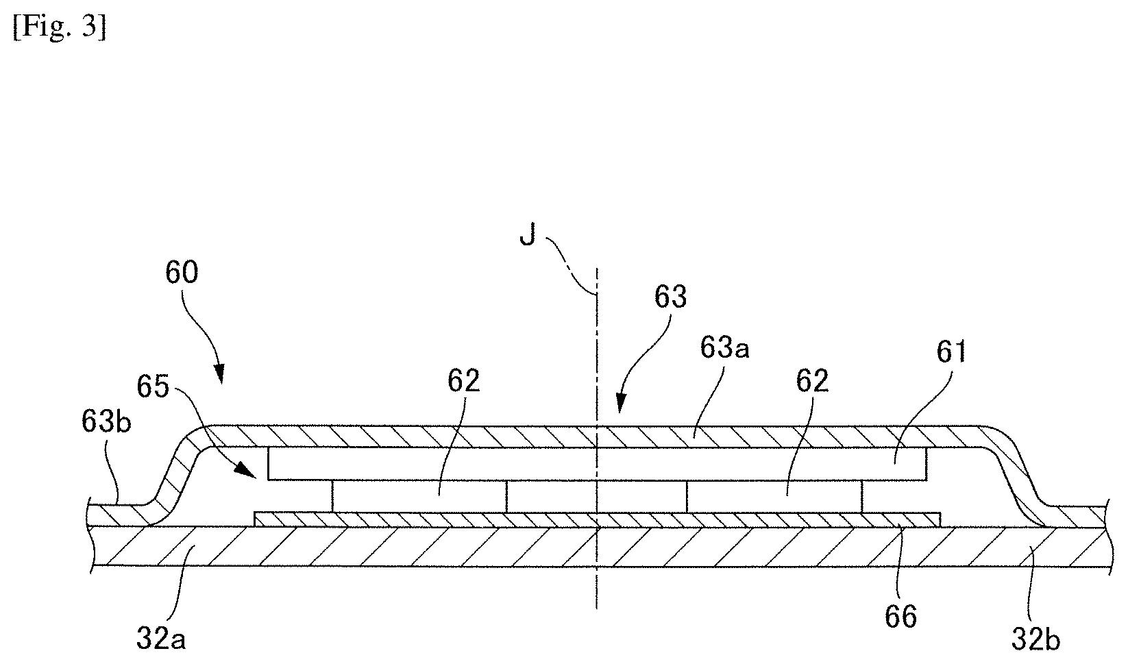
[0075] In addition, for example, positions of the circuit board and the heating elements 62 may be reversed in the axial direction, the heating elements 62 may be disposed on the rear side (-Z side) further than the circuit board 61 and thus brought in contact with the heat dissipation member 66, and meanwhile, the circuit board 61 may be brought in direct contact with the top board 63a of the inverter cover 63 with ensured insulation, as illustrated in FIG. 3 (second modified example).
[0076] Since the heating elements 62 of the inverter circuit 65 can be brought in contact with the main pump cover 32a via the heat dissipation member 66 more reliably in this modified example, cooling efficiency of the heating elements 62 can be improved. In addition, since the circuit board 61 is brought in direct contact with the top board 63a of the inverter cover 63 with ensured insulation, heat generated in the circuit board 61 can also be dissipated from the inverter cover 63.
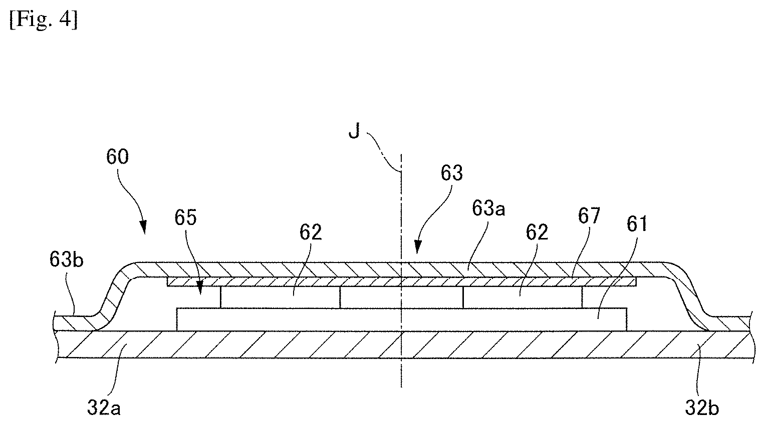
[0077] Furthermore, for example, the heat dissipation member 66 can be provided on the rear side (-Z side) of the top board 63a of the inverter cover 63 in the motor drive unit 60 and can be brought in contact with the heating elements 62, as illustrated in FIG. 4 (third modified example).
[0078] In this modified example, since the heat dissipation member 66 relating to heat conduction is sandwiched between the heating elements 62 of the inverter circuit 65 and the top board 63a and thereby the heating elements 62 can be brought in contact with the top board 63a more reliably, heat of the heating elements is effectively dissipated from the inverter cover 63 and a temperature rise is restrained.
Modified Example in which Multiple Circuit Boards are Provided
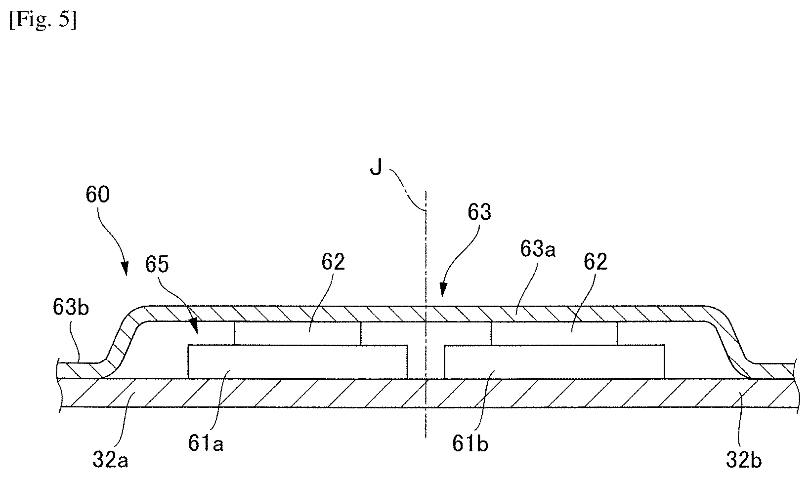
[0079] In the first example embodiment illustrated in FIG. 1, an example of the inverter circuit 65 having one circuit board 61 on which two heating elements 62 of the same type are mounted has been introduced. However, the disclosure is not limited to the inverter circuit 65 having this structure, and for example, an inverter circuit 65 having two circuit boards 61a and 61b on each of which heating elements 62 are mounted as illustrated in FIG. 5 can also be used (fourth modified example). In addition, the number of circuit boards 61 may be two or three or more. Furthermore, the number of heating elements 62 mounted on one circuit board 61 may be plural, and heating elements of different kinds (e.g., any of capacitors, microcomputers, power ICs, field effect transistors (FETs), and the like) may be used.
[0080] According to this modified example, by using multiple circuit boards 61 in the inverter circuit 65, a degree of freedom of positions of the circuit boards when the circuit boards are disposed in the motor drive unit 60 increases. With respect to a circuit board 61 on which heating elements 62 generating a large quantity of heat are mounted, for example, only the heating elements 62 can be disposed on the main pump cover 32a side as illustrated in FIG. 3. In addition, with respect to a circuit board 61 on which heating elements 62 having a large element size are mounted, the disposition thereof can be changed if there is space to do so. Accordingly, by changing disposition of the circuit board 61 in the motor drive unit 60 according to their characteristics, heat dissipation and disposition in the space can be efficiently achieved.
Modified Example in which Disposition of Inverter Circuit is Changed
[0081] In the electric oil pump 10 according to the first example embodiment illustrated in FIG. 1, the inverter circuit 65 is disposed inside the motor drive unit 60 symmetrically with respect to the central axis J. However, the disclosure is not limited to this structure, and for example, a circuit board 61a and heating elements 62 included in the inverter circuit 65 can be disposed on the -X side (the left side of the drawing) from the central axis J in the radial direction, as illustrated in FIG. 6 (fifth modified example).
[0082] As illustrated in FIG. 1, in the pump unit 30, while the inlet 32e is disposed on the -X side (the left side of the drawing) from the central axis J in the radial direction, the outlet 32f is disposed on the X side (the right side of the drawing) from the central axis J in the radial direction. Oil having a low temperature (e.g., 120.degree. C.) taken from the inlet 32e is gradually heated by heat from the inverter circuit 65 until it reaches the outlet 32f, and thus the temperature rises. Thus, cooling efficiency of oil in the pump unit 30 serving as a heat sink is lowered as it gets closer to the outlet 32f.
[0083] In this modified example, the circuit board 61a and the heating elements 62 of the inverter circuit 65 are disposed on the -X side (the left side of the drawing) from the central axis J in the radial direction. Thus, the inverter circuit 65 can be cooled with oil having a low temperature (e.g., 120.degree. C.) on the inlet 32e side whose temperature has not yet increased due to heat dissipation, and thus cooling efficiency is improved. Therefore, effective cooling can be realized, for example, by disposing the inverter circuit 65 including a field effect transistor (FET) generating a large quantity of heat at the position.
Modified Example in which Disposition of Heating Element is Changed
[0084] In the first example embodiment illustrated in FIG. 1, an example of the inverter circuit 65 having one circuit board 61 on which two heating elements 62 of the same type are mounted has been introduced. However, the disclosure is not limited to the inverter circuit 65 having this structure, and for example, an inverter circuit 65 having a structure in which a part of a heating element 68 that is not mounted on a circuit board 61c is connected to the circuit board 61c by using wiring 69, as illustrated in FIG. 7 can also be used (sixth modified example).
[0085] In this modified example, in a case in which the heating element 68 is an element generating a large quantity of heat, for example, the heating element 68 is disposed directly on a main pump cover 32a on the -X side (the left side of the drawing) from the central axis J in the radial direction, thus cooling can be performed by using oil having a low temperature (e.g., 120.degree. C.) on the inlet 32e side, and therefore effective cooling can be achieved.
[0086] Further, either or both of the heating element 68 and the circuit board 61c may be disposed on the main pump cover 32a having a heat dissipation member 66 relating to heat conduction interposed therebetween.
[0087] In the above-described sixth modified example, an example in which a part of the heating element 68 which is not mounted on the circuit board 61c is disposed directly on a main pump cover 32a on the -X side (the left side of the drawing) from the central axis J in the radial direction has been described. However, for example, a recess 32g may be provided at a part of the main pump cover 32a on the -X side (the left side of the drawing) from the central axis J in the radial direction, and the heating element 68 may be disposed inside the recess 32g via a heat dissipation member 74 and connected to the circuit board 61c by using wiring 75 as illustrated in FIG. 8 (seventh modified example).
[0088] Since the heating element 68 is disposed inside the recess 32g, a surface area of the main pump cover 32a facing the heating element 68 increases, and the heat dissipation effect is further improved. In addition, a height of the heating element 68 in the axial direction can be reduced by a height of the recess 32g, and therefore the motor drive unit 60 can be made compact as a whole. Although the heating element 68 can be housed directly in the recess 32g, it is preferable to dispose the heating element 68 inside the recess 32g via the heat dissipation member 74.
[0089] For the heat dissipation member 74, for example, a thermosetting resin having a high heat conductivity such as silicone rubber, a heat dissipation sheet, or a heat dissipation gel can be used. In a case in which a thermosetting resin is used, for example, an appropriate amount of heat dissipation member 74 is applied to the inside of the recess 32g, then the heating element 68 is fixed to the main pump cover 32a and is put into the recess 32g, and at the same time the heating element 68 is brought in pressure-contact with the heat dissipation member 74. The inside of the recess 32g can be easily filled with the heat dissipation member 74 by curing the heat dissipation member 74 in the above-described state. In addition, by forming irregularities on the surface of the main pump cover 32a or the like, the surface area can be increased, and heat dissipation effect can be further improved.
[0090] Although a component having a high height and low heat resistance, for example, a capacitor, can be exemplified as the heating element 68 housed inside the recess 32g formed on the main pump cover 32a side, other components may be used.
Second Example Embodiment
[0091] Next, an electric oil pump according to a second example embodiment of the present disclosure will be described. In the first example embodiment, an example in which the inlet 32e is provided on the -X side (the left side of the drawing) of the pump cover 32 from the central axis J in the radial direction and the outlet 32f is provided on the X side (the right side of the drawing) of the pump cover 32 from the central axis J in the radial direction has been introduced. On the other hand, in the electric oil pump of the present example embodiment, an outlet is formed at a position different from that of the pump cover 32. Differences of the present example embodiment from the first example embodiment will be mainly described below. The electric oil pump according to the present example embodiment will be given the same reference numerals as those of the same configuration of the electric oil pump according to the first example embodiment, and description thereof will not be repeated.
[0092] FIG. 9 illustrates a cross-sectional diagram of the electric oil pump according to the second example embodiment.
[0093] In the electric oil pump 100 according to the present example embodiment, a delivery port 31d that extends from a bottom of a recess 33 to a rear side (-Z side) and communicates with a motor unit 20 is provided in a pump body 31 of a pump unit 30 on an X side (the right side of the drawing) from a central axis J in a radial direction. In addition, an outlet 73 from which oil is discharged is provided on a bottom part 21a of a housing 21 at a part of the X side (the right side of the drawing) from the central axis J in the radial direction. Furthermore, an oil circulation filter 76 is provided on the rear side (-Z side) of the outlet 73 if necessary. Further, the outlet 73 may be provided at a part of a stator holding part 21b on the X side (the right side of the drawing) from the central axis J in the radial direction, rather than on the bottom part 21a of the housing 21.
Action of Present Example Embodiment
[0094] An operation when the electric oil pump device 100 according to the present example embodiment is activated will not be described since the operation is the same as the first example embodiment, and so a flow of oil will be described.
[0095] An inlet 32e of the electric oil pump 10 is connected to the oil pan (not illustrated) that stores oil, via the circulation pipe (not illustrated), and the tip of the circulation pipe on the oil pan side is immersed in the oil. The oil stored in the oil pan passes through the inlet 32e, enters inside of the electric oil pump 100, and reaches an inlet port 32c due to a negative pressure generated by rotating the inner rotor 37 of the electric oil pump 100. The oil is taken from the inlet port 32c into a pump chamber 33, then is pressure-fed to the delivery port 31d, further passes through the pump unit 30, and flows into the motor unit 20. In the motor unit 20, the oil flows the gap between the inner circumferential surface of the stator 50 and the outer circumferential surface of the rotor 40 from the front side (+Z side) to the rear side (-Z side) and is discharged to the outlet 73. Accordingly, the coil 53 of the stator 50 can be cooled with higher efficiency and thus the rotor 40 can be cooled. The discharged oil is supplied to an inside of a transmission, which is not illustrated. The supplied oil causes oil pressure at a corresponding location and then flows back to be stored in the oil pan again.
Effect of Present Example Embodiment
[0096] (1) The pump cover 32 is generally formed of a metal such as an aluminum alloy, and has a large heat capacity and surface area, and thus the pump cover has a high heat dissipation effect. In the present example embodiment, the inverter circuit 65 is disposed on the front side (+Z side) of the pump cover 32, and the circuit board 61 is in direct contact with the main pump cover 32a having the high heat dissipation effect, with ensured insulation. Furthermore, the flow path of oil is created in the pump unit 30 from the inlet 32e to the delivery port 31d, and thus oil having a temperature equal to or lower than a certain temperature (e.g., 120.degree. C.) flows inside the pump cover 32.
[0097] Thus, heat generated in the circuit board 61 is effectively cooled via the pump cover 32 and a temperature rise is restrained. That is, since the pump cover 32 in contact with oil flowing inside the pump unit 30 also performs the role as a heat sink by directly cooling the circuit board 61 of the inverter circuit 65, cooling can be effectively realized.
[0098] (2) In the present example embodiment, the heating elements 62 of the inverter circuit 65 are brought in direct contact with the top board 63a of the inverter cover 63. For this reason, heat generated by the heating elements 62 can also be dissipated from the inverter cover 63. In addition, by using a copper-inlaid substrate as the circuit board 61, heat generated in the inverter circuit 65 is more easily transmitted to the pump cover 32, and thus cooling efficiency is improved.
[0099] (3) The electric oil pump of the present example embodiment comprises the motor unit 20, the pump unit 30, and the motor drive unit 60 which are each overlapped in the axial direction and has a compact cylindrical shape, and thus it can be generally used in various transmissions.
[0100] (4) Normally, a coil generates heat most intensely in a motor. Heat generated by the coil is transmitted to the stator core. That is, since the stator 50 generates a large amount of heat in the motor unit 20, improving efficiency of cooling the stator 50 leads to improvement in cooling efficiency of the entire motor unit 20. In the present example embodiment, the rotor 40 and the stator 50 of the motor unit 20 can be cooled at the same time since oil supplied from the outside is taken into the pump unit 30 from the inlet 32e by a pump rotor 35, passes through the delivery port 31d, and flows in the motor unit 20. Since the oil circulates the inside of the motor unit 20 and absorbs heat generated by the motor, it can prevent the motor from reaching an excessively high temperature, and deterioration of rotation efficiency of the motor can be avoided. That is, the electric oil pump device 100 in a structure exhibiting a high cooling effect can be provided.
Modified Example of Second Example Embodiment
[0101] In the above-described example embodiment, the rotor 40 and the stator 50 of the motor unit 20 can be cooled at the same time by delivering oil to the inside of the motor unit 20 via the delivery port 31d. However, a configuration without the delivery port 31d can also be adoptable. In this case, the gap between the shaft 41 and the pump body 31 in the axial direction may be used. That is, the gap between the shaft 41 and the pump body 31 in the axial direction can perform a role of a delivery port through which oil is delivered from the pump unit 30 to the motor unit 20.
[0102] In this case, the through hole 31a functions as a sliding bearing member that supports the shaft 41 to be rotatable.
[0103] According to a modified example described above, it is not necessary to separately provide the delivery port 32d, and thus processing becomes easier. In addition, oil flowing from the pump unit 30 can be used as lubricating oil, and thus the oil can be efficiently delivered into the motor unit 20.
[0104] Further, a notch may be provided on at least one of the outer circumferential surface of the shaft 41 and the inner circumferential surface of the pump body 31. Accordingly, when oil passes between the shaft 41 and the pump body 31, flow path resistance can be decreased, and thus oil can be more efficiently delivered from the pump unit 30 to the motor unit 20.
[0105] In addition, another bearing can be used in the pump body 31, in addition to the above-described sliding bearing member. In this case, oil may be allowed to pass through the bearing or a gap between the shaft 41 and the bearing.
Third Example Embodiment
[0106] Next, an electric oil pump according to a third example embodiment of the present disclosure will be described. In the first example embodiment, an example in which the inlet 32e and the outlet 32f are provided in the pump cover 32 has been introduced. On the other hand, in the electric oil pump according to the present example embodiment, an inlet 32e and an outlet 32f are provided in the pump body 31. Differences of the present example embodiment from the first example embodiment will be mainly described below. The electric oil pump according to the present example embodiment will be given the same reference numerals as those of the same configuration of the electric oil pump according to the first example embodiment, and description thereof will not be repeated.
[0107] FIG. 10 illustrates a cross-sectional diagram of the electric oil pump according to the third example embodiment of the present disclosure.
[0108] In the electric oil pump 110 according to the present example embodiment, the inlet 32e extends inside the projection part 31c of the pump body 31 from the pump chamber 33 toward the -X side (the left side of the drawing) and reaches the outer surface of the projection part 31c. On the other hand, the outlet 32f extends inside the projection part 31c in the pump body 31 from the pump chamber 33 to the X side (the right side of the drawing) and reaches the outer surface of the projection part 31c.
[0109] The inlet 32e and the outlet 32f are connected to a pump rotor 35 via the inlet port 32c and the outlet port 32d respectively. Accordingly, the configuration makes intake of oil to the pump rotor 35 and discharge of oil from the pump rotor 35 possible. Specifically, oil stored in the oil pan (not illustrated) is taken into the pump chamber from the inlet 32e via the inlet port 32c due to a negative pressure generated in the pump chamber by rotation of the pump rotor 35. The taken oil is discharged from the pressurized region to the outlet 32f via the outlet port 32d.
[0110] The electric oil pump 110 according to the present example embodiment exhibits the same action and effects as the electric oil pump 10 according to the first example embodiment. In addition, since the inlet 32e and the outlet 32f are provided in the pump body 31 in the present example embodiment, the effects is better exhibited when heat that has moved to the pump body 31 is cooled.
Fourth Example Embodiment
[0111] Next, an electric oil pump according to a fourth example embodiment of the present disclosure will be described. In the present example embodiment, a bearing unit is provided in the pump body 31. Differences of the present example embodiment from the first example embodiment will be mainly described below. The electric oil pump according to the present example embodiment will be given the same reference numerals as those of the same configuration of the electric oil pump according to the first example embodiment, and description thereof will not be repeated.
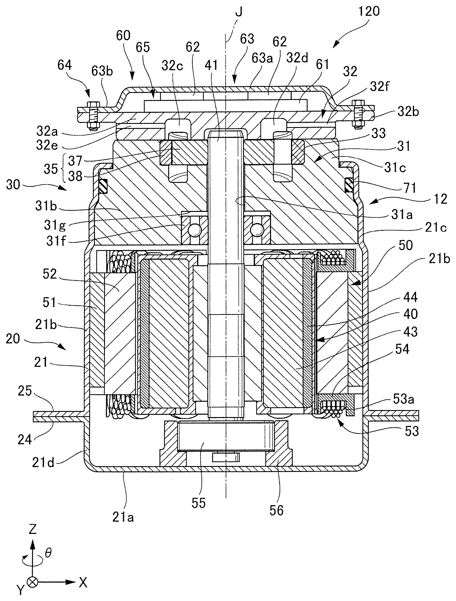
[0112] FIG. 11 illustrates a cross-sectional diagram of the electric oil pump according to the fourth example embodiment.
[0113] The electric oil pump 120 according to the present example embodiment includes a ball bearing 31f serving as a bearing unit that supports the shaft 41 on the rear side (-Z side) of the main pump body 31b.
[0114] The ball bearing 31f is fitted in the recess 31g provided in the main pump body 31b and is fixed by the main pump body 31b in a circumferential direction of the ball bearing 31f. That is, the main pump body 31b also serves as a bearing holder in the present example embodiment.
[0115] Thus, since it is not necessary to provide a new region in the main pump body 31b which a bearing holder is to be installed, an effective volume of the pump body can be increased. Thus, a heat capacity can be increased, and heat dissipation of an inverter circuit becomes easier.
[0116] In addition, the shaft 41 has a double bearing structure of the ball bearing 31f and the bearing 55 of the motor unit 20 in the present example embodiment. Thus, even if the inner rotor 37 receives a pressure caused by oil, the double bearing structure can mitigate an inclination of the shaft 41, an increase in sliding resistance can be restrained without causing the inner rotor 37 to be pushed to a wall surface of the pump case (i.e., the pump body 31 and the pump cover 32).
[0117] Furthermore, since the inlet 32e and the outlet 32f are provided in the pump cover 32 in the present example embodiment as in the first example embodiment, oil flows closer to the inverter circuit 65 in comparison to the third example embodiment in which the inlet 32e and the outlet 32f are provided in the pump body 31, and thus heat generated in the inverter circuit 65 can be effectively cooled.
[0118] Further, although an example in which the ball bearing 31f serves as a bearing unit has been introduced in the present example embodiment, another structure functioning as a bearing unit may be adopted. For example, a sliding bearing member as described in the first example embodiment and a modified example of the second example embodiment can be used instead of or together with the ball bearing 31f.
[0119] Although several example embodiments of the present disclosure have been described above, the example embodiments are merely examples and do not intend to limit the scope of the disclosure. Their example embodiments can be implemented in various other modes, and can be subject to omission, substitution, modification in various forms within a scope not departing from the subject matter of the disclosure. Their example embodiments and modifications are included within the scope of the disclosures described in the claims and equivalents thereto, as included in the scope and the subject matter of the disclosure.
[0120] Although, in the pump unit 30 of the first example embodiment, the inlet 32e is provided on the -X side (the left side of the drawing) from the central axis J in the radial direction, and the outlet 32f is provided on the X side (the right side of the drawing) from the central axis J in the radial direction, for example, the disposition of the inlet 32e and the disposition of the outlet 32f can be reversed. In this case, for the modified examples of the first example embodiment in which the inverter circuit 65 is asymmetrically disposed with respect to the central axis J (FIG. 6 to FIG. 8), the inverter circuit 65 can be disposed in a reverse direction to the central axis J. In addition, the disposition of the inverter circuit 65 according to the modified examples of the first example embodiment is also applicable to the second and fourth example embodiments. Furthermore, while the inlet 32e is provided in the pump cover 32 in the second example embodiment, the inlet 32e can also be provided in the pump body 31 as in the third example embodiment. In addition, a length, a shape, an inner diameter, and the like of the inlet 32e and the outlet 32f, and a shape, a width, a height, and the like of the inlet port 32c and the outlet port 32d according to the first and fourth example embodiments, and a length, a shape, an inner diameter, and the like of the delivery port 31d according to the second example embodiment can be appropriately changed if necessary.
[0121] This application claims the benefits of priority based on Japanese Patent Application No. 2017-040629, filed on Mar. 3, 2017, the content of which is incorporated herein by reference.
[0122] While example embodiments of the present disclosure have been described above, it is to be understood that variations and modifications will be apparent to those skilled in the art without departing from the scope and spirit of the present disclosure. The scope of the present disclosure, therefore, is to be determined solely by the following claims.
* * * * *
D00000
D00001
D00002
D00003
D00004
D00005
D00006
D00007
D00008
D00009
D00010
D00011
XML
uspto.report is an independent third-party trademark research tool that is not affiliated, endorsed, or sponsored by the United States Patent and Trademark Office (USPTO) or any other governmental organization. The information provided by uspto.report is based on publicly available data at the time of writing and is intended for informational purposes only.
While we strive to provide accurate and up-to-date information, we do not guarantee the accuracy, completeness, reliability, or suitability of the information displayed on this site. The use of this site is at your own risk. Any reliance you place on such information is therefore strictly at your own risk.
All official trademark data, including owner information, should be verified by visiting the official USPTO website at www.uspto.gov. This site is not intended to replace professional legal advice and should not be used as a substitute for consulting with a legal professional who is knowledgeable about trademark law.