Side Door Pushbutton Releases
Walawender; Chester Stanislaus ; et al.
U.S. patent application number 16/002650 was filed with the patent office on 2019-12-12 for side door pushbutton releases. The applicant listed for this patent is Ford Global Technologies, LLC. Invention is credited to Rajesh K. Patel, Chester Stanislaus Walawender.
| Application Number | 20190376324 16/002650 |
| Document ID | / |
| Family ID | 67623070 |
| Filed Date | 2019-12-12 |


| United States Patent Application | 20190376324 |
| Kind Code | A1 |
| Walawender; Chester Stanislaus ; et al. | December 12, 2019 |
SIDE DOOR PUSHBUTTON RELEASES
Abstract
A vehicle door system includes a controller and a powered latch that is configured to selectively retain a door structure in a closed position when the powered latch is latched. The powered latch permits the door to be opened when the powered latch is unlatched. An electronic door release pad is disposed on an outer side of the door structure. The door release pad includes a pad surface that faces outwardly away from the door structure. A generally flat outer side of the door structure extends around the perimeter of the pad surface. The pad surface preferably comprises a sensor. The controller is configured to generate a signal to unlatch the powered latch if the door release pad generates a signal indicating that a user has touched the pad surface and/or that an object has been detected adjacent the pad.
| Inventors: | Walawender; Chester Stanislaus; (Livonia, MI) ; Patel; Rajesh K.; (Farmington Hills, MI) | ||||||||||
| Applicant: |
|
||||||||||
|---|---|---|---|---|---|---|---|---|---|---|---|
| Family ID: | 67623070 | ||||||||||
| Appl. No.: | 16/002650 | ||||||||||
| Filed: | June 7, 2018 |
| Current U.S. Class: | 1/1 |
| Current CPC Class: | E05B 17/10 20130101; B60R 25/30 20130101; E05B 81/77 20130101; E05F 15/76 20150115; B60R 25/2036 20130101; B60R 25/01 20130101; E05F 15/60 20150115 |
| International Class: | B60R 25/01 20130101 B60R025/01; E05B 17/10 20060101 E05B017/10; E05F 15/76 20150101 E05F015/76; E05F 15/60 20150101 E05F015/60; B60R 25/30 20130101 B60R025/30; B60R 25/20 20130101 B60R025/20 |
Claims
1. A vehicle door system, comprising: a door structure configured to be movably mounted to a vehicle body structure, the door structure including an outer side; a controller; powered latch configured to retain the door structure in a closed position when the powered latch is latched, and wherein the powered latch permits the door to be opened when the powered latch is unlatched; an electronic door release pad disposed on an outer side of the door structure, the door release pad having a substantially flat sensing surface facing outwardly away from the door structure, and a perimeter extending around the flat sensing surface, the outer side of the door structure having a substantially flat outer surface extending continuously around the perimeter of the flat sensing surface in close proximity thereto; wherein the flat sensing surface of the door release pad comprises a touch sensor; and wherein the controller is configured to generate a signal to unlatch the powered latch if the door release pad generates a signal indicating that a user has touched the flat sensing surface.
2. The vehicle door system of claim 1, including: A powered actuator configured to move the door structure from a closed position to an open position after the controller causes the powered latch to unlatch.
3. The vehicle door system of claim 1, wherein: the door release pad comprises a piezoelectric sensor.
4. The vehicle door system of claim 3, wherein: The flat sensing surface of the door release pad has an elongated narrow shape defined by the perimeter and extending in a horizontal direction.
5. The vehicle door system of claim 4, wherein: the perimeter of the door release pad including a horizontally-extending lower edge that is spaced outwardly from the outer surface of the door structure, the door release pad further including a light bar extending along the lower edge, wherein the controller causes the light bar to be illuminated if a predefined condition occurs.
6. The vehicle door system of claim 5, wherein: the predefined condition is selected from the group consisting of: a user having a recognized fob approaches the vehicle, the controller unlatches the powered latch, and the controller latches the powered latch.
7. The vehicle door system of claim 5, wherein: the light bar comprises a downwardly-facing surface.
8. The vehicle door system of claim 5, wherein: the controller causes the light bar to be illuminated a first color if a first predefined condition occurs, and causes the light bar to be illuminated a second color that is not the same as the first color if a second predefined condition occurs.
9. The vehicle door system of claim 1, wherein: the flat sensing surface is at least about 4 inches long, and has a maximum vertical dimension of less than about 2 inches; and wherein substantially the entire flat sensing surface comprises a single sensing surface.
10. The vehicle door system of claim 1, including: a capacitive sensor; and wherein: the controller is configured to generate a signal to unlatch the powered latch only if: 1) the capacitive sensor detects an object; and 2) the door release pad generates a signal indicating that a user has touched the flat sensing surface.
11. The vehicle door system of claim 10, wherein: the touch sensor is selected from the group consisting of force resistance sensor, load sensors, inductive sensors, and piezo sensors.
12. The vehicle door system of claim 1, including: a light source configured to illuminate an edge of the door release pad when the controller generates a signal to unlatch the powered latch.
13. The vehicle door system of claim 12, wherein: the light source is configured to generate green light when the controller generates a signal to unlatch the powered latch, and to generate red light if the door is in a locked state.
14. The vehicle door system of claim 2, wherein: the controller is configured to unlock and unlatch the door and actuate the powered actuator to open the door if an authenticated keycard is detected.
15. The vehicle door system of claim 1, including: a sensing system configured to detect humans in the vicinity outside the vehicle; and wherein: the controller is configured to: 1) determine the intent of the detected humans; and 2) only unlock or unlatch the powered latch if the intent is to enter the vehicle.
16. A vehicle door, comprising: a powered latch and a powered door opener mounted to a door structure; a stationary horizontally elongated piezoelectric strip on an outside of the door structure; and a controller configured to illuminate a lower edge of the piezoelectric strip if a fob is detected, and unlatch the powered latch followed by actuating the door opener if a single touch is detected anywhere on the piezoelectric strip.
17. The vehicle door of claim 16, wherein: the piezoelectric strip has a flat outer surface.
18. The vehicle door of claim 16, wherein: the piezoelectric strip comprises a pad having an upper edge that is flush with an outer surface of the door structure, and a lower edge that is spaced outwardly away from the outer surface of the door structure.
19. The vehicle door of claim 18, wherein: the lower edge of the piezoelectric strip includes a surface that faces downwardly.
20. The vehicle door of claim 19, wherein: the downwardly-facing surface comprises a light-transmitting material, and including: an LED light source disposed in the pad to illuminate the downwardly facing surface.
Description
FIELD OF THE INVENTION
[0001] The present invention generally relates to vehicle door releases, and more particularly relates to a vehicle door that includes a sensor pad or button that can be utilized to unlatch and open a door.
BACKGROUND OF THE INVENTION
[0002] Various types of vehicle doors and door handles have been developed. Outside door handles typically protrude outwardly from the door. These door handles may be mechanically connected to a door latch by a linkage, and movement of the door handle is typically required to unlatch the door. However, existing door handles may suffer from various drawbacks.
SUMMARY OF THE INVENTION
[0003] According to one aspect of the present disclosure, a vehicle door system includes a door structure that is configured to be movably mounted to a vehicle body structure. The vehicle door system further includes a controller and a powered latch that is configured to retain the door structure in a closed position when the powered latch is latched. The powered latch permits the door to be opened when the powered latch is unlatched. The vehicle door system further includes an electronic door release pad that is disposed or fixed on an outer side of the door structure. The door release pad may have a substantially flat sensing surface facing outwardly away from the door structure, and a perimeter extending around the flat sensing surface. An outer side of the door structure may have a substantially flat outer surface extending continuously around the perimeter of the flat sensing surface in close proximity thereto. The flat sensing surface of the door release pad preferably comprises a sensor, such as a touch sensor and/or a capacitive sensor. The controller is configured to generate a signal to unlatch the powered latch if the door release pad generates a signal indicating that a user has touched the flat sensing surface and/or that an object has been detected adjacent the door release pad.
[0004] Embodiments of the first aspect of the disclosure can include any one or a combination of the following features: [0005] The door releases/unlatches if a capacitive sensor detects a user and also detects a force change applied to the door release pad. [0006] The controller may be configured to require both a change in capacitance and a force change before generating a door unlatch command. [0007] The door release pad or a region of the door adjacent the door release pad may illuminate upon activation to open, or turn red when the vehicle door is locked and latched. [0008] The vehicle door may be designed to operate as a "approach unlock/unlatch and power present the door" and walk away lock (as a person with a fob or keycard who is the legitimate owner of the vehicle with an authenticating fob or keycard walk away from the vehicle, the vehicle will lock itself). [0009] The vehicle door may include a powered actuator that initially shifts the door to a partially open presented position after the powered latch is unlatched. [0010] The vehicle door may have a substantially smooth outer surface without a protruding handle.
[0011] A vehicle door system according to another aspect of present disclosure including a powered latch and a powered door opener mounted to door structure. The vehicle door further includes a stationary horizontally elongated piezoelectric strip on the outside of the door. The vehicle door further includes a controller that is configured to illuminate a lower edge of the piezoelectric strip if a fob is detected. The controller is further configured to unlatch the powered latch followed by actuation of the door opener if a single touch is detected anywhere on the piezoelectric strip.
[0012] These and other aspects, objects, and features of the present invention will be understood and appreciated by those skilled in the art upon studying the following specification, claims, and appended drawings.
BRIEF DESCRIPTION OF THE DRAWINGS
[0013] In the drawings:
[0014] FIG. 1 is a partially schematic side elevational view of a vehicle door according to one aspect of the present disclosure;
[0015] FIG. 2 is a partially schematic cross sectional view of the vehicle door of FIG. 1 taken along the line II-II;
[0016] FIG. 3 is a cross sectional view of a portion of the vehicle door of FIG. 1 taken along the line
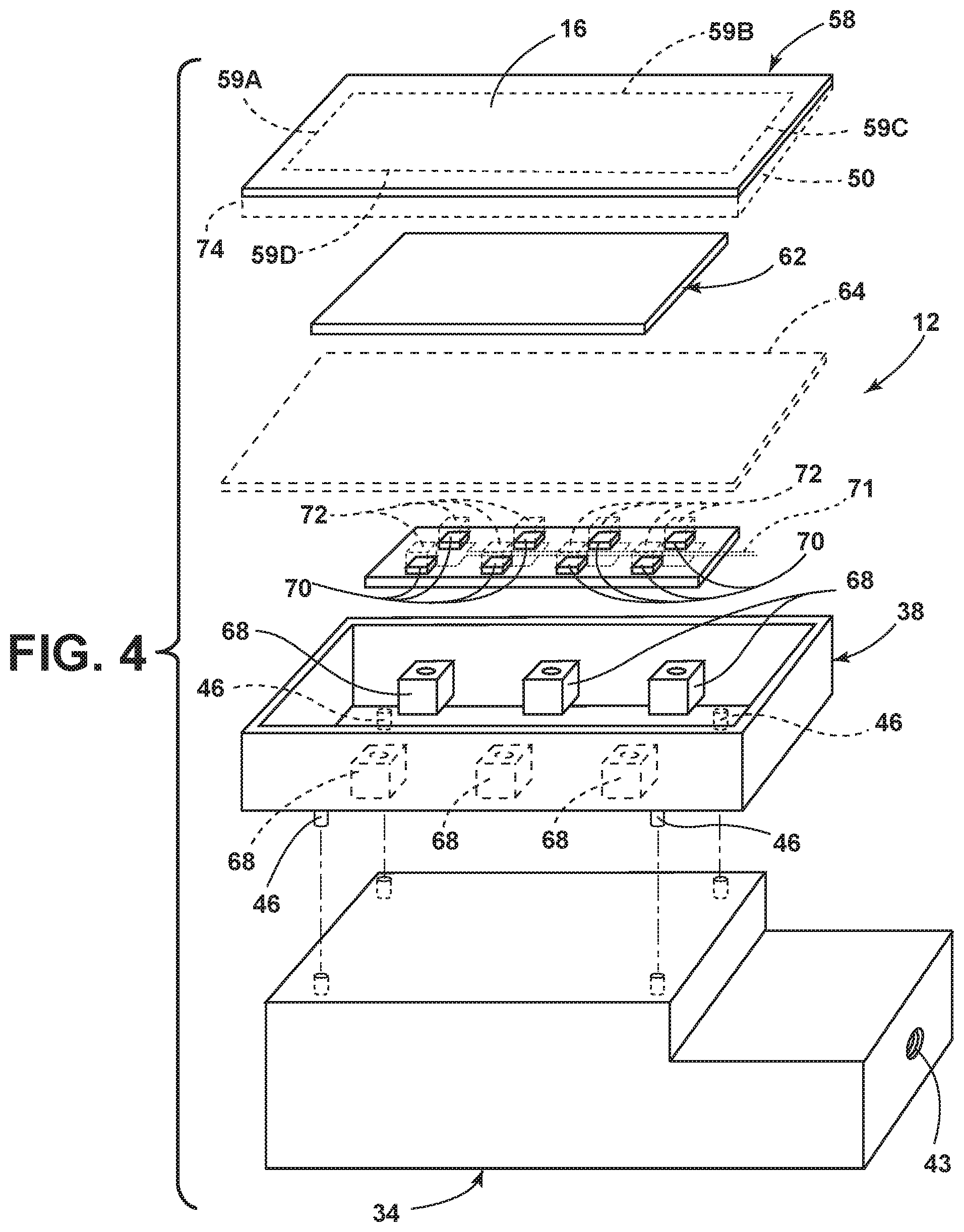
[0017] FIG. 4 is an exploded perspective view of a sensor pad assembly according to one aspect of the present disclosure;
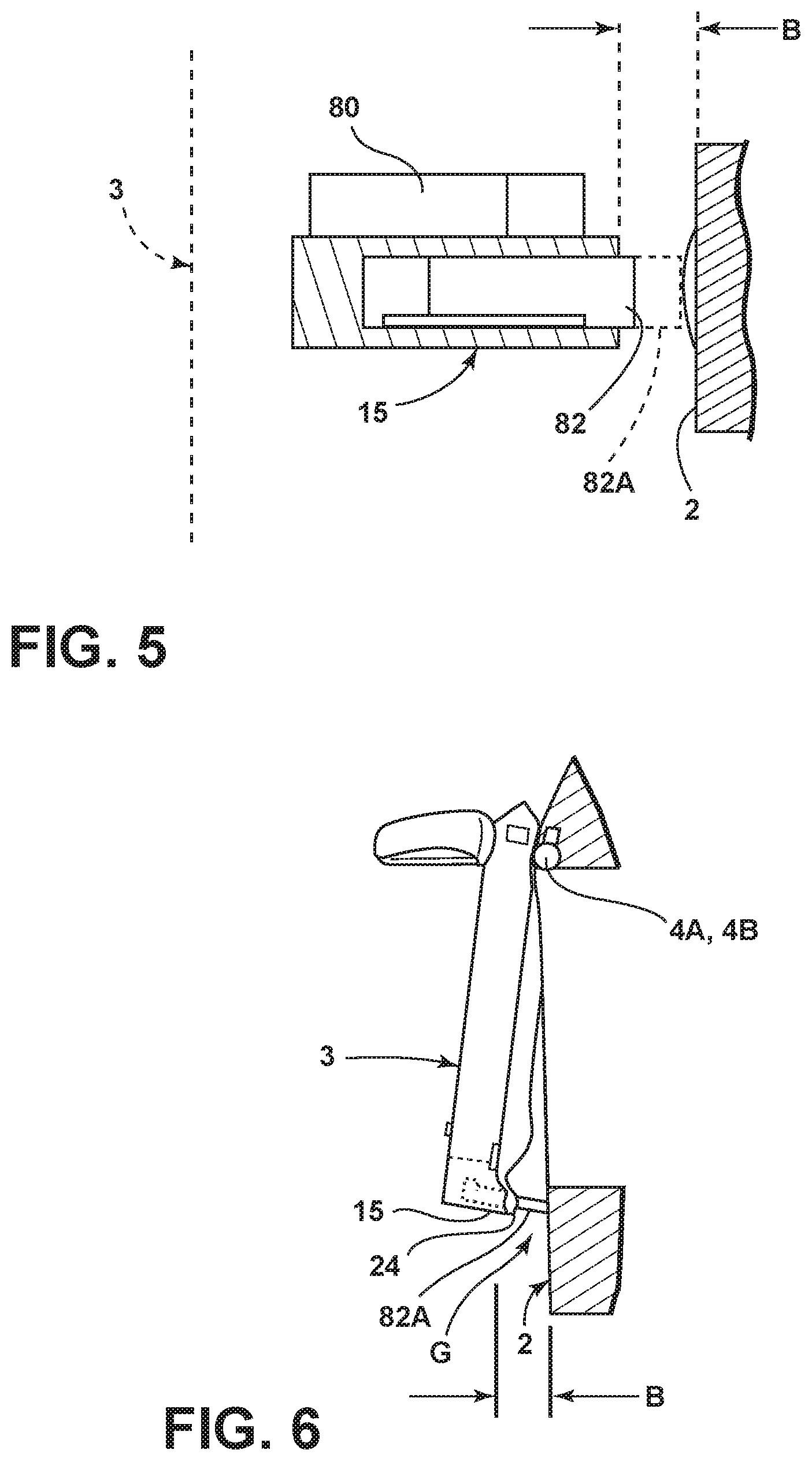
[0018] FIG. 5 is a partially schematic view of a powered actuator that initially opens the vehicle door to a partially open "presented" position;
[0019] FIG. 6 is a partially schematic top plan view showing the vehicle door in a partially open "presented" position.
DETAILED DESCRIPTION OF THE PREFERRE EMBODIMENTS
[0020] For purposes of description herein, the terms "upper," "lower," "right," "left," "rear," "front," "vertical," "horizontal," and derivatives thereof shall relate to the disclosure as oriented in FIG. 1. However, it is to be understood that the disclosure may assume various alternative orientations, except where expressly specified to the contrary. It is also to be understood that the specific devices and processes illustrated in the attached drawings, and described in the following specification are simply exemplary embodiments of the inventive concepts defined in the appended claims. Hence, specific dimensions and other physical characteristics relating to the embodiments disclosed herein are not to be considered as limiting, unless the claims expressly state otherwise.
[0021] In this document, relational terms, such as first and second, top and bottom, and the like, are used solely to distinguish one entity or action from another entity or action, without necessarily requiring or implying any actual such relationship or order between such entities or actions. The terms "comprises," "comprising," or any other variation thereof, are intended to cover a non-exclusive inclusion, such that a process, method, article, or apparatus that comprises a list of elements does not include only those elements but may include other elements not expressly listed or inherent to such process, method, article, or apparatus. An element proceeded by "comprises . . . a" does not, without more constraints, preclude the existence of additional identical elements in the process, method, article, or apparatus that comprises the element.
[0022] With reference to FIG. 1, a motor vehicle 1 includes a body structure 2 and a door 3 having a door structure 5 that is movably mounted to the body structure 2 by suitable structure such as hinges 4A and 4B. The vehicle door 3 comprises a door system that includes a door structure 5 and a controller 6. A powered latch 8 is operably connected to the controller 6. The controller 6 and powered latch 8 may be operably connected to an electrical power supply 10. It will be understood that electrical power supply 10 may comprise one or more batteries or other suitable sources of electrical power.
[0023] The powered latch 8 is configured to retain the door structure 5 in a closed position when the powered latch 8 is latched, and the powered latch 8 permits the door to be opened when the powered latch is unlatched. Powered latch 8 may comprise a powered door latch as described in U.S. patent application Ser. No. 14/696,749, filed on Apr. 27, 2015, entitled ELECTRONIC SAFE DOOR UNLATCHING OPERATIONS, the entire contents of which are incorporated herein by reference.
[0024] The vehicle door 3 further includes a door release pad 12 that is disposed or fixed on an outer side 14 of the door structure 5 (see also FIG. 2). The door release pad 12 includes a substantially flat surface 16 that faces outwardly in the direction of "A" of FIG. 2 away from the door structure 5. The door release pad 12 further includes a perimeter 18 extending around the flat sensing surface 16 as shown in FIGS. 2 and 3. The outer side of the door structure 5 has a substantially flat outer surface 20 extending continuously around the perimeter 18 of the flat sensing surface 16 in close proximity thereto. As discussed in more detail below, the flat surface 16 of the door release pad 12 may comprise a sensing surface including touch sensor and/or other suitable sensors (e.g. capacitive sensitivity). The controller 6 may be configured to generate a signal to unlatch the powered door latch 8 if the door release pad 12 generates a signal indicating that a user has touched the flat sensing surface 16. As discussed in more detail below, a connection with FIGS. 5 and 6, vehicle 1 may include a powered actuator 15 that shifts door 3 to a partially open position to permit a user to grasp rear edge 24 of door 3 to pull door 3 to a fully open position.
[0025] Referring again to FIG. 1, the perimeter 18 of door release pad 12 is generally oblong, with an elongated narrow shape extending in a horizontal direction. Perimeter 18 has a length "L", a height "H" at a forward N22 of door release pad 22, and a height "H2" at a rearward end 23 of the door release pad. The dimensions L, H and H2 may be varied as required for a particular application. In general, the length L is preferably about 150-200 mm, the height H is about 25 mm, and the dimension H2 is about 12 mm. However, it will be understood that virtually any size or shape may be utilized. The door release pad 12 may be positioned in an upper rear portion 25 of door 3 adjacent rear edge 24 below beltline 26 of door 3. The beltline 26 generally comprises the region of outer skin 27 of door structure 5 immediately below window 28 of door 3. Thus, the door release pad 12 may be positioned in a region of door 3 that is commonly used to mount conventional protruding door handles. This position of door release pad 12 is typically more intuitive for users who are accustomed to using conventional door handles. However, it will be understood that the door release pad 12 is not a door handle in a conventional sense, and door release 12 does not need to include a gripping feature that a user could grasp to pull the door 3 open. In general, the door release pad 12 could have virtually any shape or size, and could be positioned in virtually any location either on door 3 or on vehicle body 2. For example, a door release pad 12 could be mounted on a rear portion of frame 29 of door structure 5 adjacent window 28. As discussed in more detail below, a fob 30 may be configured to communicate wirelessly with controller 6 to provide for authentication of a user to permit unlatching of powered door latch 8 if fob 30 recognized (authorized). The fob 30 may optionally include a key 31 that is configured to engage in optional lock cylinder 32 in the event the door release pad 12 or other electrical components malfunction.
[0026] With further reference to FIGS. 2 and 3, door release pad 12 may comprise a housing 38 that is secured to the door structure 5 by a support structure 34. In the illustrated example, the support structure 34 is secured to a rear edge structure 40 (FIG. 3) of door structure 5 by a threaded fastener 42 that engages a threaded opening 43 of support structure 34. The housing 38 may comprise a polymer material, and may be disposed in a shallow pocket 44 formed in outer skin 27 of door structure 5. Housing 38 may include pins 46 that extend through openings 48 in outer skin 27 in end pocket 44 to thereby locate and secure the housing 38 to the door structure 5. It will be understood that a wide variety of housings, mounting structures and the like may be utilized to secure the door release pad 12 to the door structure 5.
[0027] Referring again to FIG. 2, a horizontally extending lower edge 50 of door release pad 12 may optionally project outwardly away from outer side 14 of door structure 5 such that a lower edge portion of door release pad 12 is spaced outwardly (e.g. 5 mm or other suitable dimension) from outer surface 20 of door structure 5. The edge 50 may be illuminated by LEDs or other suitable light sources to form a "light bar" that projects light 52 downwardly adjacent door 3 if predefined conditions occur. Light 52 may have sufficient brightness to illuminate a ground surface below and adjacent door 3 at night. The edge 50 may comprise a downwardly-facing surface extending along a generally horizontal lower perimeter portion 18A. In a preferred embodiment, only the lower perimeter portion 18A at edge 50 is illuminated. However, the entire perimeter 18 of door release pad 12 may be illuminated, or only selected portions of perimeter 18 may be illuminated. For example, a horizontal upper portion 18 of perimeter 18 may be illuminated, and may transit light 52A outwardly in the direction of arrow "A". Also, lower perimeter 18A may be flush with outer surface 20 of door structure 5 such that surface 16A of door release pad 12 is flush (substantially coplanar) with surface 20.
[0028] The door release pad 12 may be operably interconnected to powered door latch 8 by conductors such as electrical lines 54 and a 5-pin sealed connector 56, or other suitable connecting arrangement. It will be understood that the various components of vehicle 1 may be configured to communicate via electrically conductive lines, fiber optic lines, wireless communication systems, or virtually any other suitable arrangement.
[0029] With reference to FIGS. 3 and 4, door release pad 12 may comprise an outer layer 58 having an edge portion 59 that overlaps a portion 60 of outer skin 27 around the pocket 44. The outer layer 58 may comprise a light-transmitting polymer material or other suitable material. Optionally, a region 60A of outer skin 27 may be recessed inwardly in an amount that is approximately equal to a thickness of outer layer 58, such that flat sensing surface 16 formed by outer layer 58 is substantially co-planar with flat outer surface 20 of outer skin 27 of door structure 5.
[0030] The door release pad 12 also includes a sensor 62 that is positioned immediately inside outer layer 58, and a printed circuit board 66. An optional support structure such as plate 64 may be utilized to support the sensor 62 on internal supports 68 of housing 38. The sensor 62 may comprise a capacitive sensor that is configured to detect the presence of an object (e.g. a user's hand) that is located directly adjacent the flat sensing surface 16 formed by outer layer 58. The sensor 62 may also comprise a force resistance sensor, a load sensor, an inductive sensor, or a piezoelectric sensor. As discussed above, the door release pad 12 is operably connected to the controller 6. In particular, the sensor 62 may be operably connected to the controller 6. The controller 6 may be configured to "look for" (i.e. require) both a capacitance change and a force change before allowing an unlatched signal to the powered door latch 8 to be processed. More specifically, as noted above, the sensor 62 may comprise a capacitive sensor in combination with a second sensing capability, wherein the second sensing capability comprises one or more of 1) force resistance, 2) load sensing, 3) inductive sensing, or 4) piezoelectric sensing. If sensor 62 is configured in this manner, controller 6 may be configured to ignore a "capacitive only" signal or a "force change only" signal from sensor 62. If controller 6 is required to receive two separate inputs from sensor 62, this reduces inadvertent unlatching that could otherwise result if sensor 62 comprises only a capacitive sensor or only a second sensor (wherein the second sensor comprises one of a force resistance sensor, a load sensor, an inductive sensor, or a piezoelectric sensor). Controller 6 may also be configured to require detection.
[0031] Alternatively, the sensor 62 may comprise a single sensor. For example, the sensor 62 may comprise a force sensor only, such that a force applied to flat sensing surface 16 by a user will be detected by sensor 62, causing a signal to be sent to the controller 6. Controller 6 may optionally be configured to require an authorization signal from fob 30 or other suitable authorization signal in addition to detection of a force on flat sensing surface 16 in order to generate an unlatched signal to powered door latch 8.
[0032] Alternatively, sensor 62 may comprise a capacitive sensor only, and controller 6 may be configured to unlatch powered latch 8 if a user's hand is detected in the vicinity of sensing surface 16.
[0033] Referring again to FIG. 4, one or more light sources such as LEDS 70 may be mounted to the printed circuit board 66. Printed circuit board 66 may include electrical conductors 71 that operably interconnect the printed circuit board 66 to the controller 6. One or more light pipes 72 may be configured to transmit light from the LEDS 70 to one or more edge portions 59A-59D of outer layer 58 to thereby illuminate selected portions of outer layer 58. Outer layer 58 may comprise a transparent or translucent light-transmitting polymer material. It will be understood that the light pipes 72 are shown in schematic form in FIG. 4. Also, light pipes 72 may comprise transparent polymer, and may be configured as required to illuminate one or more specific portions of outer layer 581n particular, outer layer 58 may include an edge 74 having an increased thickness to thereby form an illuminated edge 50. As discussed above, the illuminated edge 50 may face downwardly (FIG. 2) to project light 52A downwardly.
[0034] LEDS 70 may be configured to provide various colors and intensities of light. For example, if a user having an authorized fob 30 approaches the vehicle 1, controller 6 may be configured to cause LEDS 70 to illuminate to provide a soft blue or soft white color light 52A and/or 52B (FIG. 2). The same light may change to green when the controller 6 unlocks and/or unlatches powered door latch 8. Also, controller 6 may be configured to cause the LEDS to generate red light if the vehicle door 3 is latched and locked. It will be understood that the powered door latch 8 may have a locked and unlocked state (e.g. stored in memory), and latch 8 may require unlocking (e.g. require detection of an authorized fob 30) prior to generating an unlatch signal. This locking and unlatching function may generally correspond to locking and unlatching functions of conventional mechanical door latches which require the door to be unlocked, and also require movement of a handle to mechanically unlatch the door latch.
[0035] With reference to FIGS. 5 and 6, the door system may include a powered door opening device 15 having an electrically-powered actuator 80 and a plunger 82 that extends to an extended position 82A upon actuation of the electric actuary 80. The door opening device 15 is operably connected to the controller 6. During operation of door 3, the controller 6 unlocks and unlatches powered door latch 8 according to predefined criteria as discussed in more detail above. After the powered door latch 8 is unlatched, controller 6 causes the door opening device 15 to be actuated, thereby shifting plunger 82 outwardly to move door 3 from a closed position to an open position. The door opening device 15 is preferably positioned adjacent rear edge 24 of door 3, such that the door opening device 15 partially opens door 3 when the electric actuator 80 is actuated. The rear edge 24 of door 3 may be positioned outwardly a distance "B", thereby forming a gap "G" between the rear edge 24 of door 3 and the vehicle body structure 2 upon actuation of door opening device 15. A user can then insert a portion of his or her hand into the gap "G" and pull the door 3 to a fully opened position. Thus, the door opening device 15 permits the door 3 to be grasped and pulled to a fully opened position without the need for an external handle on door 3. The door opening device 15 may comprise an actuator as described in detail in U.S. patent application Ser. No. 15/269,281, filed on Sep. 19, 2016, entitled ANTI-PINCH LOGIC FOR DOOR OPENING ACTUATOR, the entire contents of which are hereby incorporated herein by reference.
[0036] It will be understood by one having ordinary skill in the art that construction of the described disclosure and other components is not limited to any specific material. Other exemplary embodiments of the disclosure disclosed herein may be formed from a wide variety of materials, unless described otherwise herein.
[0037] For purposes of this disclosure, the term "coupled" (in all of its forms, couple, coupling, coupled, etc.) generally means the joining of two components (electrical or mechanical) directly or indirectly to one another. Such joining may be stationary in nature or moveable in nature. Such joining may be achieved with the two components (electrical or mechanical) and any additional intermediate members being integrally formed as a single unitary body with one another or with the two components. Such joining may be permanent in nature or may be removable or releasable in nature unless otherwise stated.
[0038] It is also important to note that the construction and arrangement of the elements of the disclosure as shown in the exemplary embodiments is illustrative only. Although only a few embodiments of the present innovations have been described in detail in this disclosure, those skilled in the art who review this disclosure will readily appreciate that many modifications are possible (e.g., variations in sizes, dimensions, structures, shapes and proportions of the various elements, values of parameters, mounting arrangements, use of materials, colors, orientations, etc.) without materially departing from the novel teachings and advantages of the subject matter recited. For example, elements shown as integrally formed may be constructed of multiple parts or elements shown as multiple parts may be integrally formed, the operation of the interfaces may be reversed or otherwise varied, the length or width of the structures and/or members or connector or other elements of the system may be varied, the nature or number of adjustment positions provided between the elements may be varied. It should be noted that the elements and/or assemblies of the system may be constructed from any of a wide variety of materials that provide sufficient strength or durability, in any of a wide variety of colors, textures, and combinations. Accordingly, all such modifications are intended to be included within the scope of the present innovations. Other substitutions, modifications, changes, and omissions may be made in the design, operating conditions, and arrangement of the desired and other exemplary embodiments without departing from the spirit of the present innovations.
[0039] It will be understood that any described processes or steps within described processes may be combined with other disclosed processes or steps to form structures within the scope of the present disclosure. The exemplary structures and processes disclosed herein are for illustrative purposes and are not to be construed as limiting.
[0040] It is to be understood that variations and modifications can be made on the aforementioned structure without departing from the concepts of the present invention, and further it is to be understood that such concepts are intended to be covered by the following claims unless these claims by their language expressly state otherwise.
* * * * *
D00000
D00001
D00002
D00003
D00004
D00005
XML
uspto.report is an independent third-party trademark research tool that is not affiliated, endorsed, or sponsored by the United States Patent and Trademark Office (USPTO) or any other governmental organization. The information provided by uspto.report is based on publicly available data at the time of writing and is intended for informational purposes only.
While we strive to provide accurate and up-to-date information, we do not guarantee the accuracy, completeness, reliability, or suitability of the information displayed on this site. The use of this site is at your own risk. Any reliance you place on such information is therefore strictly at your own risk.
All official trademark data, including owner information, should be verified by visiting the official USPTO website at www.uspto.gov. This site is not intended to replace professional legal advice and should not be used as a substitute for consulting with a legal professional who is knowledgeable about trademark law.