Grooving Device for Underground Structures and Its Construction Method
Wang; Yubin
U.S. patent application number 16/479214 was filed with the patent office on 2019-12-12 for grooving device for underground structures and its construction method. The applicant listed for this patent is Yubin Wang. Invention is credited to Yubin Wang.
| Application Number | 20190376257 16/479214 |
| Document ID | / |
| Family ID | 58944117 |
| Filed Date | 2019-12-12 |


View All Diagrams
| United States Patent Application | 20190376257 |
| Kind Code | A1 |
| Wang; Yubin | December 12, 2019 |
Grooving Device for Underground Structures and Its Construction Method
Abstract
A working method for a trench-cutting device for underground construction, including the following steps: 1) setting up working platforms in working wells at two ends; 2) mounting the trench-cutting device so that the two ends of the trench-cutting device are each in one of the two working wells respectively; 3) enabling the trench-cutting device to cut along a contour line of an underground construction section; and 4) excavating earth along the contour line. Also disclosed is a trench-cutting device for underground construction, consisting of an excavating device (1) and translation devices (2); the excavating device (1) mainly consists of a frame (1-1), a cutting chain (3) and transmission devices (1-2); the frame (1-1) consists of a frame (1-1-1) in a trench and two end frames (1-1-2) outside of the trench; the two end frames (1-1-2) are respectively connected to the translation devices (2) in the two working wells, the transmission devices (1-2) are mounted on the two end frames (1-1-2), and the translation devices (2) are both arranged in the working wells at the two ends. The working platform is set up in four working wells, concrete may be filled in behind as the trench-cutting device excavates the earth, and then after a closed cavity is formed, work is conducted in the cavity. Also disclosed is a trench-cutting device.
| Inventors: | Wang; Yubin; (Wuxi, Jiangsu, CN) | ||||||||||
| Applicant: |
|
||||||||||
|---|---|---|---|---|---|---|---|---|---|---|---|
| Family ID: | 58944117 | ||||||||||
| Appl. No.: | 16/479214 | ||||||||||
| Filed: | January 13, 2018 | ||||||||||
| PCT Filed: | January 13, 2018 | ||||||||||
| PCT NO: | PCT/CN2018/072524 | ||||||||||
| 371 Date: | July 18, 2019 |
| Current U.S. Class: | 1/1 |
| Current CPC Class: | E02F 3/08 20130101; E02D 2250/0023 20130101; E02D 15/02 20130101; E02F 5/14 20130101; E02F 3/143 20130101; E02F 5/06 20130101 |
| International Class: | E02F 5/06 20060101 E02F005/06; E02D 15/02 20060101 E02D015/02; E02F 3/14 20060101 E02F003/14 |
Foreign Application Data
| Date | Code | Application Number |
|---|---|---|
| Jan 18, 2017 | CN | 201710038036.2 |
Claims
1. Grooving device construction method for the underground structure is mainly characterized in the steps below: 1) Build a working platform in working shafts on both ends; 2) Install the grooving device, so that two ends of grooving device are built in two working shafts separately by two methods: (a) Drill holes to thread grooving devices; (b) Groove directly from the external side (e.g. above or on one lateral side of the mountain); 3) The grooving device cuts grooves along the contour line of the section of the underground structure by two methods: (1) Carry out grooving and grouting at the same time; (2) Groove without grouting concrete; 4) Excavate the rock and soil in the contour line.
2. As claim 1, the grooving device for underground structures is characterized in the said grooving device consisted of the excavating device and the translation device; the excavating device 1 mainly consists of frame, chain blade and transmission device; chain blade consists of chain and blade fixed on the chain; frame consists of in-groove frame and both-end frame outside the groove. The in-groove frame consists of the front frame and rear frame. The front frame is equipped with a track for chain blade operation on the front, and the both-end frames are separately connected to the translation device in two working shafts and mounted with a transmission device. The translation device consists of a transmission device and chain wheels and equipped with translation devices in working shafts on both ends. During construction, the translation device in working shafts on both ends drives corresponding both-end frames simultaneously to move according to the specified structure contour track, with the both-end frame driving the chain blades on the front-end track of the in-groove frame along the same track. The driving device drives the chain blade. The blades on the front track of the front frame excavates rock and soil to groove, with chain blade bringing the excavated rock and soil into the working shaft; the in-groove frame is of two types of structures: 1) Chain blade track is mounted at the back of the front track of the front frame, which is adopted to form a closed loop as the chain returns. The front frame is connected to the rear frame in the groove by two methods: (A) The total width of the blade on the excavated face is equivalent to that of the non-excavated face. The multi-row chain blade is in a staggered arrangement on the non-excavated face. The front frame integrates to the rear frame through the staggered space; (B) The center line of the chain blade is a spatial curve. The blades returning to the chain blade adjacent to the non-excavated face are engaged in a staggered or overlapped way along the longitudinal direction of the chain, i.e. the total width of the blade on the non-excavated face is less than the total width of the blade on the excavated face. The front and rear frames are integrated according to this width difference; 2) Two sets of excavating devices share one set of chain blades, i.e. the chain of two chain blades are connected in series to form a closed loop.
3. As claim 2, the grooving device for underground structures is characterized in multi-row chain blade and blades of a self-grinding structure.
4. As claim 2, the grooving device for underground structures is characterized in a spatial curve that is the chain center line of the chain blade.
5. As claim 2, the grooving device for underground structures is characterized in that the said chain blade replaces chains and blades in the working shaft, to meet different geological conditions and thickness requirements.
6. As claims 2 and 3, the grooving device for underground structures is characterized in that the said chain blade is a multi-row chain blade, and the multi-row chain blade can excavate simultaneously or separately as necessary.
7. As claim 6, the grooving device for underground structures is characterized in that the said multi-row chain blade is arranged in a cone shape on the excavated face.
8. As claims 1 and 2, the grooving device for underground structures is characterized in that the said construction methods can be divided into method A and method B. The said method A includes both grooving and grouting at the same time, and concrete nozzles are equipped at the tail end of the rear frame. The said method B is to groove only without grouting.
9. As claim 6, the grooving device for underground structures is characterized in that for the said method A, a reinforcement arrangement device is equipped at the back of the rear frame, so that the concrete after grouting contains reinforcement.
10. As claim 1, the grooving device for underground structures is characterized in that the said working shafts are existing structures.
Description
FIELD OF THE INVENTION
[0001] The present invention relates to a grooving device for underground structures and its construction method, which belongs to the field of civil engineering foundation construction.
BACKGROUND OF THE INVENTION
[0002] The current tunnel construction method includes: open-cut construction and tunneling construction with pipe jacking or shield; open-cut construction features a large amount of earthwork, a long construction period and a high cost; the cost of existing tunneling construction methods is relatively high.
SUMMARY OF THE INVENTION
[0003] The present invention provides a grooving device for underground structures and its construction method. Its object is to overcome the shortcomings of existing technologies. Its main advantages are as follows: Build working platforms in four working shafts. The grooving device can excavate rock and soil, while grouting at the back, which forms a closed cavity for further construction. It has less influence on the surrounding environment, which is of simple construction, good quality, a short construction period, and a low cost.
[0004] The Technical Scheme of the Invention:
[0005] Grooving device construction method includes the steps below:
1) Build a working platform in working shafts on both ends. 2) Install the grooving device, so that two ends of the grooving device are built in two working shafts; there are mainly two methods: (a) Drill holes to thread the grooving device; (b) Groove directly from the external side (e.g. above or on one lateral side of the mountain); 3) The grooving device cuts grooves along the contour line of the section of the underground structure by two methods: (1) Carry out grooving and grouting at the same time; (2) Carry out grooving without grouting concrete; 4) Excavate the rock and soil in the contour line.
[0006] The grooving device consists of the excavating device and the translation device; the excavating device mainly consists of frame, chain blade and transmission device; chain blade consists of chains and blades on the chain; frame consists of an in-groove frame and both-end frame outside the groove. The in-groove frame consists of the front frame and rear frame. The front frame is equipped with a track for chain blade operation on the front, and the both-end frames are separately connected to the translation device in two working shafts and mounted with a transmission device. The translation devices in working shafts on both ends consist of a transmission device and chain wheels and equipped with translation devices in working shafts on both ends. During construction, the translation device in working shafts on both ends drives corresponding both-end frame simultaneously to move according to the specified structure contour track, with the both-end frame driving the chain blades on the front-end track of the in-groove frame along the same track and the driving device driving the chain blade. The blades on the front track of the front frame excavate rock and soil to groove, while the chain blade brings the excavated rock and soil to the working shaft. In-groove frame is in two structures:
[0007] 1) Chain blade track is mounted at the back of the front track of the front frame, which is adopted to form a closed loop as the chain returns. The front frame is connected to the rear frame in the groove by two methods: [0008] (A) The total width of the blade on the excavated face is equivalent to that of the non-excavated face. The multi-row chain blade is in a staggered arrangement on the non-excavated face. The front frame integrates to the rear frame through the staggered space; [0009] (B) The center line of the chain blade is a spatial curve. The blades returning to the chain blade adjacent to the non-excavated face are engaged in a staggered or overlapped way along the longitudinal direction of the chain, i.e. the total width of the blade on the non-excavated face is less than the total width of the blade on the excavated face. The front and rear frames are integrated according to this width difference;
[0010] 2) Two sets of excavating devices share one set of chain blades, i.e. the chain of two chain blades are connected in series to form a closed loop.
[0011] The advantages of the present invention: structure working platforms in four working shafts enables the grooving device to excavate rock and soil, while grouting into the rear side to form a closed cavity for further construction, which has less influence on the surrounding environment and is of simple construction, good quality, a short construction period and a low cost.
DETAILED DESCRIPTION OF THE DRAWINGS
[0012] FIG. 1 is a structural schematic diagram of the excavating device 1 for both grooving and grouting, which is also a structural schematic diagram of the inner frame 1-1-1 and the both-end frame 1-1-2 outside the groove consisting of the frame 1-1. It is also a structural schematic diagram of the driving device 1-2-1, the tensioning device 1-2-2 and the chain wheel 1-2-3 consisting of the driving device 1-2;
[0013] FIG. 2 is the A-A view of FIG. 1. It is also the structural schematic diagram of grouting and reinforcement arrangement device 5 in front of the cut groove during operation of excavating device 1, which is also the structural schematic diagram of front frame 1-1-1-1 and rear frame 1-1-1-2 consisting of in-groove 1-1-1;
[0014] FIG. 3 is the B-B view of FIG. 2 and the structural schematic diagram of reinforcement arrangement device 5 of the excavating device 1;
[0015] FIG. 4 is the C-C view of FIG. 2. It is also the structural schematic diagram for the staggered engagement arrangement of the blades returning to chain blade 3 adjacent to the non-excavated face of the excavating device 1 along the longitudinal direction of the chain. The track of chain blade 3 is retracted inward on both ends, which are paralleled in the middle section, so the width of the non-excavated face of the excavating device 1 is smaller than the width of the excavated face;
[0016] FIG. 5 is the D view of FIG. 2, and is also the structural schematic diagram of the multi-row chain blade 3 for the excavated face of the excavating device 1;
[0017] FIG. 6 is a structural schematic diagram of the double-row chain blade 3 in a staggered arrangement on the non-excavated face for the excavating device 1;
[0018] FIG. 7 is a structural schematic diagram of chain blade 3, (a) is a structural schematic diagram of chain 3-1 and blade 3-2, and a structural schematic diagram of cross of chain 3-1 consisted of A cross 3-1-1 and B cross 3-1-2, which is also the structural schematic diagram of chain 3-1 to realize spatial bending. (b) is a structural schematic diagram of chain blade 3 consisted of flexible belt 3-1B and blade 3-2B, and a structural schematic diagram of flexible belt 3-1B and blade 3-2B;
[0019] FIG. 8 is a structural schematic diagram of the excavating device 1 with grooving function instead of grouting function, which is also a structural schematic diagram of driving device 1-2-1, tensioning device 1-2-2 and chain wheel 1-2-3 consisted of the transmission device 1-2.
[0020] FIG. 9 is the A-A view of FIG. 8. It is also a structural schematic diagram of the excavating device 1 with grooving instead of grouting. It is also a structural schematic diagram of two excavating devices sharing one piece of chain blade 3;
[0021] FIG. 10 is a schematic diagram of excavating two-end working shafts;
[0022] FIG. 11 is a schematic diagram of drilling and wire threading 6 for both-end working shafts;
[0023] FIG. 12 is a schematic diagram for two pieces of chain blades 3 by threading wire 6, mounting of translation device 2 and excavating device;
[0024] FIG. 13 is the A-A view of FIG. 12 and a structural schematic diagram of the flat device 2. The flat device 2 drives the excavating device 1 to move along the contour line of the structure. The grooving device 1 moves along the contour line, while the flat device 2 drives the grooving device 1 to rotate;
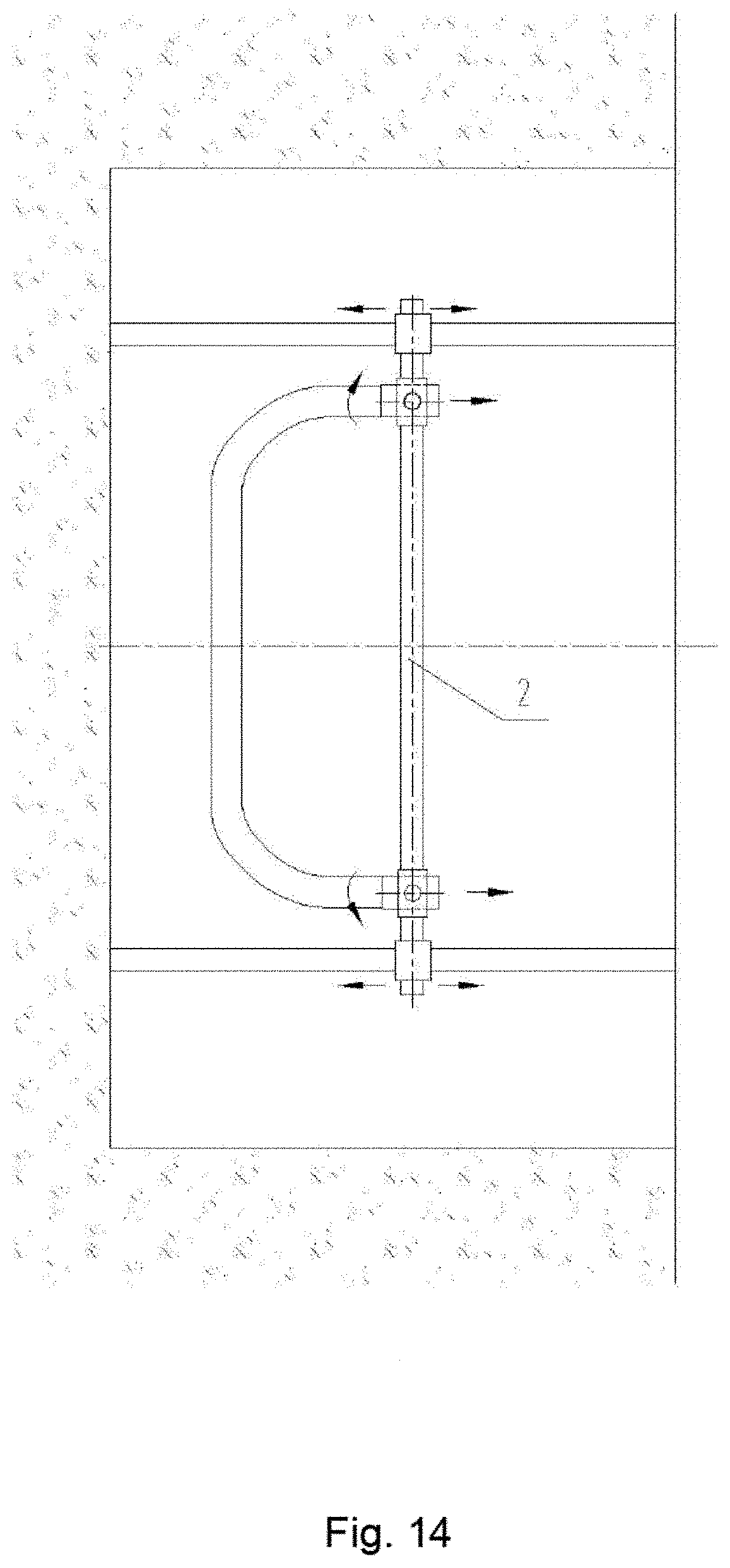
[0025] FIG. 14 is a schematic diagram for the position of the translation device 2 after the partial completion of grooving by excavating device 1 by both grooving and grouting operations.
[0026] FIG. 15 is a middle sectional view when the excavating device 1 is located in the position of FIG. 14, and is also a structural schematic diagram of the contour formed during grooving and grouting by the excavating device 1;
[0027] FIG. 16 is a middle sectional view shown at the end of the traveling of the excavating device 1 according to the specified track. It is also a structural schematic diagram for the complete contour formed by grooving and grouting the edge by the excavating device 1;
[0028] FIG. 17 is a schematic diagram for the area in the contour line of FIG. 16 after complete removal of rock and soil;
[0029] FIG. 18 is a schematic diagram of the position of the translation device 2 after partial completion of grooving by the excavating device 1 with an only grooving function instead of grouting;
[0030] FIG. 19 is a middle sectional view when the excavating device 1 is located at the position as shown in FIG. 18. It is also a structural schematic diagram of the contour formed by the excavating device 1 with grooving function instead of grouting;
[0031] FIG. 20 is a middle sectional view at the completion of the traveling of the excavating device 1 according to the specified track. It is also a structural schematic diagram of the complete contour formed by the excavating device 1 with the only grooving operation instead of grouting;
[0032] FIG. 21 is a diagram of the area in the contour line of FIG. 20 after the removal of rock and soil;
[0033] FIG. 22 is a structural schematic diagram of a chain blade track of the grooving device. There are five types of tracks, i.e. A, B, C1, C2 and D. Among them, A is of a plane type, B is of a convex type, and C1 and C2 are of a concave type;
[0034] FIG. 23 is a structural schematic diagram of D in a cone shape with multi-row tracks in a staggered arrangement along the longitudinal direction;
[0035] FIG. 24 is a structural schematic diagram of the structure of the Type D track and multi-row chain blade;
[0036] FIG. 1 illustrates the excavating device consisting of the grooving device, including frame 1-1, driving device 1-2 and chain blade 3; 1-1 is the frame of the excavating device 1, which consists of in-groove frame 1-1-1 and both-end frame 1-1-2; 1-1-1 is the in-groove frame of the excavating device 1-1, which consists of front frame 1-1-1-1 and rear frame 1-1-2; 1-1-1-1 is the front frame of in-groove frame 1-1-1; 1-1-1-2 is the rear frame of the in-groove frame 1-1-1; 1-1-2 is the both-end frame outside the groove 1-1-1 of the excavating device 1-1; 1-2 is the transmission device of the excavating device 1, which consists of driving device 1-2-1, tensioning device 1-2-2 and chain wheel 1-2-3, etc.; 2 is the translation device consisted of the grooving device, which drives the both-end frame 1-1-2 of the excavating device 1 to move along the contour line of the structure. While the both-end frame 1-1-2 is moving along the contour line, the translation device will drive the in-groove frame of the excavating device 1 to rotate; 3 is the chain blades consisting of chain 3-1 and blade 3-2; 3-1 is the chains consisting of chain blade 3, including caterpillars, wires and flexible belts; 3-1-1 is the A cross consisting of chain cross; 3-1-2 is the B cross consisting of the chain cross; 3-1B is the flexible belt consisting of chain blade 3; 3-2 is the blade for rock and soil excavation fixed on the chain 3-1. 3-2B is the blade for rock and soil excavation fixed on the flexible belt 3-1B; 4 is the concrete nozzles on the tail end of rear frame 1-1-1-2; the reinforcement arrangement device on the tail end of rear frame 1-1-1-2, and; 6 is the steel wire rope.
DETAILED DESCRIPTION OF IMPLEMENTATION
[0037] A construction method for grooving device adopted in underground structures mainly includes the steps below:
[0038] 1) Build a working platform in working shafts on both ends.
[0039] 2) Install the grooving device, so that two ends of the grooving device are built in two working shafts; there are mainly two methods: [0040] (a) Drill holes to thread grooving devices; [0041] (b) Groove directly from the external side (e.g. above or on one lateral side of the mountain);
[0042] 3) The grooving device cuts grooves along the contour line of the section of the underground structure by two methods: [0043] (1) Carry out grooving and grouting at the same time; [0044] (2) Groove without grouting concrete;
[0045] 4) Excavate the rock and soil in the contour line.
[0046] The said grooving device consists of the excavating device and the translation device; the excavating device mainly consists of frame, chain blade and transmission device; chain blade consists of chains and blades on the chain; frame consists of an in-groove frame and both-end frame outside the groove. The in-groove frame consists of the front frame and rear frame. The front frame is equipped with a track for chain blade operation on the front, and the both-end frames are separately connected to the translation device in two working shafts and mounted with a transmission device. The translation devices in working shafts on both ends consist of a transmission device and chain wheels and equipped with translation devices in working shafts on both ends. During construction, the translation device in working shafts on both ends drives corresponding both-end frame simultaneously to move according to the specified structure contour track, with the both-end frame driving the chain blades on the front-end track of the in-groove frame along the same track and the driving device driving the chain blade. The blades on the front track of the front frame excavate rock and soil to groove, while the chain blade brings the excavated rock and soil to the working shaft. In-groove frame is in two structures:
[0047] 1) Chain blade track is mounted at the back of the front track of the front frame, which is adopted to form a closed loop as the chain returns. The front frame is connected to the rear frame in the groove by two methods: [0048] (A) The total width of the blade on the excavated face is equivalent to that of the non-excavated face. The multi-row chain blade is in a staggered arrangement on the non-excavated face. The front frame integrates to the rear frame through the staggered space; [0049] (B) The center line of the chain blade is a spatial curve. The blades returning to the chain blade adjacent to the non-excavated face are engaged in a staggered or overlapped way along the longitudinal direction of the chain, i.e. the total width of the blade on the non-excavated face is less than the total width of the blade on the excavated face. The front and rear frames are integrated according to this width difference;
[0050] 2) Two sets of excavating devices share one set of chain blades, i.e. the chain of two chain blades are connected in series to form a closed loop.
[0051] The chain blade is a multi-row chain blade, and the blade is a self-grinding structure.
[0052] The center line of the chain of the chain blade is a spatial curve.
[0053] The chain blade replaces chains and blades in the working shaft, to meet different geological conditions and thickness requirements.
[0054] The chain blade is a multi-row chain blade, and the multi-row chain blade can excavate simultaneously or separately as necessary.
[0055] The multi-row chain blade is arranged in a cone shape on the excavated face.
[0056] The construction methods could be divided into method A and method B.
[0057] The method A includes both grooving and grouting at the same time, and concrete nozzles are equipped at the tail end of the rear frame.
[0058] The method B is to groove only without grouting.
[0059] For the method A, a reinforcement arrangement device is equipped at the back of the rear frame, so that the concrete after grouting contains a reinforcement.
[0060] The working shafts are existing structures.
[0061] The present invention is further described below in conjunction with the drawings attached.
[0062] As shown in FIGS. 1-7, the grooving device consists of the excavating device 1 and the translation device 2; the excavating device 1 mainly consists of frame 1-1, transmission device 1-2 and chain blade 3; chain blade 3 consists of chains 3-1 and blades 3-2 on the chain; frame 1-1 consists of in-groove frame 1-1-1 and both-end frame outside the groove 1-1-2. The in-groove frame 1-1-1 consists of front frame 1-1-1-1 and rear frame 1-1-1-2. The front frame 1-1-1-1 is equipped with a track for chain blade operation on the front, and the both-end frame 1-1-2 are separately connected to the translation device 2 in two working shafts and mounted with a transmission device. The translation device 1-2 consists of a transmission device 1-2-1, tensioning device 1-2-2 and chain wheels 1-2-3 and equipped with translation devices 2 in working shafts on both ends. During construction, the translation device 2 in working shafts on both ends drive corresponding both-end frame 1-1-2 simultaneously to move according to the specified structure contour track, with the both-end frame 1-1-2 driving the chain blades 3 on the front-end track of the in-groove frame. The driving device 1-2-1 drives the chain blade 3-1, which drives the blade 3-2 to operate. The blades 3-2 on the front track of the front frame 1-1-1-1 excavate rock and soil to groove, with the concrete nozzles on the tail end of the rear frame 1-1-1-2 grouting concrete and the reinforcement arrangement device 5 on the tail end of rear frame 1-1-1-2 arranging reinforcement, i.e. construction method A.
[0063] As shown in FIGS. 8-9, the excavating device 1 of the grooving device grooves only without grouting, and the two sets of excavating devices share one chain blade 3, i.e. construction method B.
[0064] As shown in FIGS. 2, 4 and 5, blade 3-2 returning to chain blade 3 adjacent to the non-excavated face of the excavating device 1 are engaged in a staggered arrangement or overlapped along the longitudinal direction of the chain, i.e. the total width of the blade on the non-excavated face is less than that of the blade on the excavated face, and the front frame 1-1-1-1 and the rear frame 1-1-1-2 are integrated by this width difference.
[0065] As shown in FIG. 6, the total width of the chain blade 3 of the excavated face of the excavating device 1 equals that of the chain blade 3 of the non-excavated face of the excavating device 1, and the multi-row chain blades are in a staggered arrangement on the non-excavated face. The front frame 1-1-1-1 is integrated to the rear frame 1-1-1-2 through the staggered space.
[0066] As shown in FIGS. 10-13, a working platform and a translation device 2 are built in the two ends of the working shaft with the steel wire rope 6 adopted to thread the chain blade 3 through holes drilled, and then through the excavating device 1. The translation device 2 drives the excavating device 1 to move along the contour line of the structure from the bottom, while the excavating device 1 rotates along the contour line.
[0067] As shown in FIGS. 14-17, the construction method A of the grooving device: while the excavating device 1 of grooving device grooves along the contour line of underground structure cross-section, carry out grouting and finally clear the rock and soil within the contour line of concrete.
[0068] As shown in FIGS. 18-21, the construction method B of grooving device: while the excavating device 1 of grooving device grooves along the contour line of underground structure cross section, carry out grouting and finally clear the rock and soil within the contour line.
* * * * *
D00000
D00001
D00002
D00003
D00004
D00005
D00006
D00007
D00008
D00009
D00010
D00011
D00012

D00013

D00014
D00015

D00016

D00017

D00018

D00019

D00020

D00021

D00022

XML
uspto.report is an independent third-party trademark research tool that is not affiliated, endorsed, or sponsored by the United States Patent and Trademark Office (USPTO) or any other governmental organization. The information provided by uspto.report is based on publicly available data at the time of writing and is intended for informational purposes only.
While we strive to provide accurate and up-to-date information, we do not guarantee the accuracy, completeness, reliability, or suitability of the information displayed on this site. The use of this site is at your own risk. Any reliance you place on such information is therefore strictly at your own risk.
All official trademark data, including owner information, should be verified by visiting the official USPTO website at www.uspto.gov. This site is not intended to replace professional legal advice and should not be used as a substitute for consulting with a legal professional who is knowledgeable about trademark law.