Pillar With Load-branching Nodes And Adjustable Run-out Angle
BRUGGENBROCK; Michael ; et al.
U.S. patent application number 16/477403 was filed with the patent office on 2019-12-12 for pillar with load-branching nodes and adjustable run-out angle. This patent application is currently assigned to ThyssenKrupp Steel Europe AG. The applicant listed for this patent is thyssenkrupp AG, ThyssenKrupp Steel Europe AG. Invention is credited to Michael BRUGGENBROCK, Andreas COTT, Stephan DREWES, Lothar PATBERG, Klaus PLAUMANN, Marcus RAUHUT, Ingo ROGNER, Ralf STEGMEYER.
| Application Number | 20190376244 16/477403 |
| Document ID | / |
| Family ID | 61024753 |
| Filed Date | 2019-12-12 |


| United States Patent Application | 20190376244 |
| Kind Code | A1 |
| BRUGGENBROCK; Michael ; et al. | December 12, 2019 |
PILLAR WITH LOAD-BRANCHING NODES AND ADJUSTABLE RUN-OUT ANGLE
Abstract
The present invention relates to a free pillar having a shaft, a load-branching node provided at the upper end of the shaft and at least two cantilever arms which are each connected at one end to the load-branching node and at the other end support the superstructure, and is characterized in that the load-bearing node includes a dome surface and a number of cantilever arm connections which corresponds to the number of cantilever arms, and in that the cantilever arm connections are arranged in such a manner that the center axes of the cantilever arm connections and of the shaft meet at a common point of intersection.
| Inventors: | BRUGGENBROCK; Michael; (Rosendahl, DE) ; COTT; Andreas; (Dusseldorf, DE) ; DREWES; Stephan; (Monchengladbach, DE) ; PATBERG; Lothar; (Moers, DE) ; RAUHUT; Marcus; (Mulheim an der Ruhr, DE) ; ROGNER; Ingo; (Ingolstadt, DE) ; STEGMEYER; Ralf; (Medebach, DE) ; PLAUMANN; Klaus; (Bergkamen, DE) | ||||||||||
| Applicant: |
|
||||||||||
|---|---|---|---|---|---|---|---|---|---|---|---|
| Assignee: | ThyssenKrupp Steel Europe
AG Duisburg DE thyssenkrupp AG Essen DE |
||||||||||
| Family ID: | 61024753 | ||||||||||
| Appl. No.: | 16/477403 | ||||||||||
| Filed: | January 16, 2018 | ||||||||||
| PCT Filed: | January 16, 2018 | ||||||||||
| PCT NO: | PCT/EP2018/050943 | ||||||||||
| 371 Date: | July 11, 2019 |
| Current U.S. Class: | 1/1 |
| Current CPC Class: | E04C 3/32 20130101; E01D 4/00 20130101; E04B 1/24 20130101; E04B 2001/2406 20130101; E04H 12/185 20130101; E01D 19/02 20130101; E04B 1/58 20130101 |
| International Class: | E01D 19/02 20060101 E01D019/02; E01D 4/00 20060101 E01D004/00 |
Foreign Application Data
| Date | Code | Application Number |
|---|---|---|
| Jan 17, 2017 | DE | 10 2017 200 671.4 |
Claims
1. A free pillar having a shaft, a load-branching node provided at the upper end of the shaft and at least two cantilever arms which are each connected at one end to the load-branching node and at the other end support the superstructure, wherein the load-branching node includes a dome surface and a number of cantilever arm connections which corresponds to the number of cantilever arms, and in that the cantilever arm connections are arranged in such a manner that the center axes of the cantilever arm connections and of the shaft meet at a common point of intersection.
2. The pillar as claimed in claim 1, wherein the dome surface comprises a form which is at least symmetrical to a plane of symmetry running through the center axis of the shaft or rotationally symmetrical to the center axis of the shaft.
3. The pillar as claimed in claim 2 wherein, the dome surface is realized substantially in the form of a spherical segment, and in that the cantilever arm connections are connected to the dome surface via circular surfaces, as a result of which the common point of intersection of the center axes lies in the center of the spherical segment.
4. The pillar as claimed in claim 3, wherein the cantilever arms are connected to the cantilever arm connections by means of screw flanges.
5. The pillar as claimed in claim 3, wherein the cantilever arm connections are realized in one piece with the cantilever arms.
6. The pillar as claimed in claim 5, wherein the load-branching node includes a transition, wherein the dome surface is connected to the shaft by means of the transition, and wherein the transition compensates for at least one of different diameters and cross-sectional forms of the shaft and of the dome surface.
7. The pillar as claimed in claim 6, wherein the transition comprises at least one of a continually changing diameter and cross section.
8. The pillar as claimed in claim 7 wherein the parts of the load-branching node are welded together.
9. The pillar as claimed in claim 8 wherein bulkhead plates are provided in the load-branching node.
10. The pillar as claimed in claim 9 wherein the cantilever arms are realized as tubing with one of a constant and conical cross section.
11. The pillar as claimed in claim 10, wherein the cantilever arms are one of curved and molded in 3D.
12. The pillar as claimed in claim 11 wherein the shaft is realized as a spirally welded tube.
Description
FIELD
[0001] Pillars have long been known in civil engineering for supporting higher positioned components. These are usually realized in the form of columns which comprise a uniform cross section or a narrowing, that is to say a tapering, from the base up to the superstructure. For the support of overhangs with a larger-area extent, a load-branched structure with an enlarged span is necessary which conducts forces from a larger surface to the pillar insofar as the superstructure has not been realized in a self-supporting manner or dynamic loads occur. The use of crossbeams or cantilever beams, in particular in conjunction with multiple columns or the use of framework structures is usual for this purpose.
BACKGROUND
[0002] CN 102259166 A discloses a spherical cast node, on which multiple connection flanges are distributed over the surface in order to enable the connection of struts. Said cast node is provided, in particular, for application in framework structures. A disadvantage in this connection, however, is the costly production and the inflexible design, that is to say the lack of subsequently being able to adapt to the positioning, size and number of the connection flanges as the angles and positions can be different depending on the realization of the respective application
SUMMARY
[0003] The object underlying the invention is, consequently, to provide a pillar which comprises an enlarged span and is flexibly adaptable to the conditions of the respective application. A further object of the invention is to achieve the aforenamed object with components which are as identical as possible or are designed in as identical a manner as possible and require as small a space as possible.
[0004] Secondary objects are an esthetic appearance and cost-efficient producibility.
[0005] Said object is achieved by a free pillar, also designated below in general as a pillar, with the features of claim 1.
[0006] It is provided according to the invention that a free pillar having a shaft, a load-branching node provided at the upper end of the shaft and at least two cantilever arms which are each connected at one end to the load-branching node and at the other end support the superstructure, is characterized in that the load-branching node includes a dome surface and a number of cantilever arm connections which corresponds to the number of cantilever arms, and that the cantilever arm connections are arranged in such a manner that the center axes of the cantilever arm connections and of the shaft meet at a common point of intersection. As a result of such a design, a relatively intricate look can be achieved for the pillar structure, in particular when using steel as the material. Consequently, only a relatively small installation surface is required and, above all in connection with a corresponding equally relatively intricate superstructure, there is only a small amount of shading of the regions located below.
[0007] Preferred embodiments of the pillar are characterized in that the dome surface comprises a form which is at least symmetrical to a plane of symmetry running through the center axis of the shaft or rotationally symmetrical to the center axis of the shaft. Forms such as pyramids, cones and domes are generated in this connection, which enables a correspondingly symmetrical arrangement of the cantilever arms or of the cantilever arm connections. The symmetrical design about the center axis improves the introduction of force to the shaft, as a result of which the flow of forces is able to be optimized. In dependence on the design and the design requirements, the forms of the dome surface can comprise rounded edges and/or, for example, can be realized as truncated pyramids or cones. The surfaces with which the cantilever arm connections are connected to the dome surface are simplified in said design. A 3D trim can be necessary, nevertheless, in the case of, for example, ellipsoidal dome surfaces.
[0008] A particularly preferred embodiment of the pillar is characterized in that the dome surface is realized substantially in the form of a spherical segment, and that the cantilever arm connections are connected to the dome surface via circular surfaces, as a result of which the common point of intersection of the center axes lies in the center of the spherical segment. In place of the simple tubular portions, realizations where the run-out angle of the cantilever arms is able to be adjusted variously with reference to the dome surface are naturally also possible as a result of corresponding 3D trimming. The spherical segment is a special form of the rotationally symmetrical realization of the dome surface, through which simple tubular portions can be used as cantilever arm connections and the run-out angles of the cantilever arm connections are able to be adjusted arbitrarily with reference to the shaft, an alignment of the center axes according to the invention being ensured at the same time. It is preferred, in this connection, that the segment height is smaller than or equal to the radius, in a particularly preferred manner smaller than or equal to half the radius, of the dome surface. In order to be able to arrange the at least two cantilever arm connections on the dome surface without them having to be directly connected together, the minimum height of the dome surface has, however, in this case, to fulfill the following condition, where h.sub.k stands for the height of the spherical segment, r.sub.k for the radius of the spherical segment and d.sub.A for the diameter of the cantilever connection to the dome surface:
h K .gtoreq. d A 2 2 .times. r K ##EQU00001##
[0009] In a further preferred embodiment of the invention, the dome surface is generated from a steel plate by means of a forming process. Corresponding methods for the forming of steel plates are known per se to the expert. An advantage of said preferred embodiment is that correspondingly produced dome surfaces comprise substantially more constant wall thicknesses than dome surfaces produced, for example, by steel casting.
[0010] In a further preferred embodiment of the invention, the dome surface is situated in the upper region of the load-branching node and includes the connections to the cantilever arms entirely.
[0011] In a further preferred embodiment of the invention, the dome surface is arched upward and outward.
[0012] In further embodiments of the invention, the pillar is characterized in that the cantilever arms are connected to the cantilever arm connections by means of screw flanges. In dependence on the span and on the ratio between the shaft height and the overall height of the pillar, long cantilever arms are necessary where applicable. In order to simplify the assembly and the alignment of the cantilever arm connections to the dome surface here, said connections are realized separately from the cantilever arms. The connection of the cantilever arms to the cantilever arm connections is then effected by means of screw flanges, in particular inside flanges, for which, where applicable, another assembly opening has to be provided on at least one of the two component parts.
[0013] In alternative embodiments to the aforenamed, above all in the case of relatively small pillar heights, the pillars are characterized in that the cantilever arm connections are realized in one piece with the cantilever arms. As a result, the number of parts is reduced, which reduces expenditure on transport and production.
[0014] Further embodiments of the pillar are characterized in that the load-branching node includes a transition, wherein the dome surface is connected to the shaft by means of the transition, and wherein the transition compensates for different diameters and/or cross-sectional forms of the shaft and of the dome. With regard to the design, identical cross-sectional forms of the shaft and the dome surface are, as a rule, preferred, in the majority of cases round or with a polygonal cross section, it being possible, however, for the diameters to differ, the corresponding dimension, such as edge length, periphery, inner circle, etc., in the case of polygons also being included here with the diameter as designation in the application. Different diameters can be provided for the cantilever arm connections, for example on account of the space requirement on the dome surface when a smaller diameter is sufficient for the support load for the shaft.
[0015] In the case of embodiments of the pillar with transition, the pillar can be characterized in that the transition comprises a continually changing diameter and/or cross section. For example, conical transitions, which widen the shaft diameter upward to the diameter of the dome surface, are generated for this purpose in the case of round cross sections. As an alternative to this, to generate a mushroom-shaped appearance the transition can also be realized as a solid level plate or as a cone directed downward from the upper shaft end.
[0016] Embodiments of the pillar are characterized in that the parts of the load-branching node are welded together. When using steel as material for the components of the pillar, the latter are welded together in a preferred manner, in particular the parts of the load-branching node can be connected in this way to form an assembly, as a result of which expenditure on transport and assembly is able to be reduced.
[0017] For reinforcement, in embodiments of the invention pillars can be characterized in that bulkhead plates are provided in the load-branching node. In particular, in the case of larger diameters, the rigidity of the components can be improved in this manner without increasing the thicknesses of the walls.
[0018] Embodiments of the pillar are characterized in that the cantilever arms are realized as tubing with a constant or conical cross section. In the simplest and most cost-efficient production, the cantilever arms can be produced from tubes with a constant diameter. Cantilever arms, which taper conically upward and at the same time enable a weight saving, are also sufficient on account of the force progression and in view of the design.
[0019] Embodiments of the pillar according to the invention are characterized in that the cantilever arms are curved or molded in 3D. Above all for design reasons or also in order to ensure specific clear widths, such as vertical clearance at a certain width of span between two pillars, the cantilever arms can also comprise a curved progression. 3D molded cantilever arms are to be understood as cantilever arms, the center axis of which is molded in more than one direction over the length of the cantilever arm.
[0020] Pillars of embodiments according to the invention are characterized, in particular, in that the shaft is realized as a spirally welded tube. Arbitrary diameters and tube lengths which enable a constant or also conical cross-sectional development are both easily possible as a result.
[0021] In a further preferred embodiment of the invention, the outline of the center line of at least 2 cantilever arms does not extend parallel to the outline of the center line of the lane of the bridge structure.
[0022] Further areas of applicability of the teachings of the present disclosure will become apparent from the detailed description, claims and the drawings provided hereinafter, wherein like reference numerals refer to like features throughout the several views of the drawings. It should be understood that the detailed description, including disclosed embodiments and drawings referenced therein, are merely exemplary in nature intended for purposes of illustration only and are not intended to limit the scope of the present disclosure, its application or uses. Thus, variations that do not depart from the gist of the present disclosure are intended to be within the scope of the present disclosure.
BRIEF DESCRIPTION OF THE DRAWINGS
[0023] The invention is explained in more detail below by way of schematic drawings, similar-type components being provided with identical reference symbols, in which in detail:
[0024] FIG. 1 shows a pillar in an embodiment of the invention,
[0025] FIG. 2 shows a further view of the upper part of the embodiment in FIG. 1,
[0026] FIG. 3 shows an alternative embodiment of the invention analogous to that shown in FIG. 2,
[0027] FIG. 4 shows an embodiment of the lower parts of a pillar according to the invention,
[0028] FIG. 5 shows a further embodiment of the lower parts of a pillar according to the invention,
[0029] FIG. 6 shows a further embodiment of the lower parts of a pillar according to the invention including cantilever arm connections,
[0030] FIG. 7 shows a use of the pillar according to the invention as an example in the case of a bridge.
DESCRIPTION
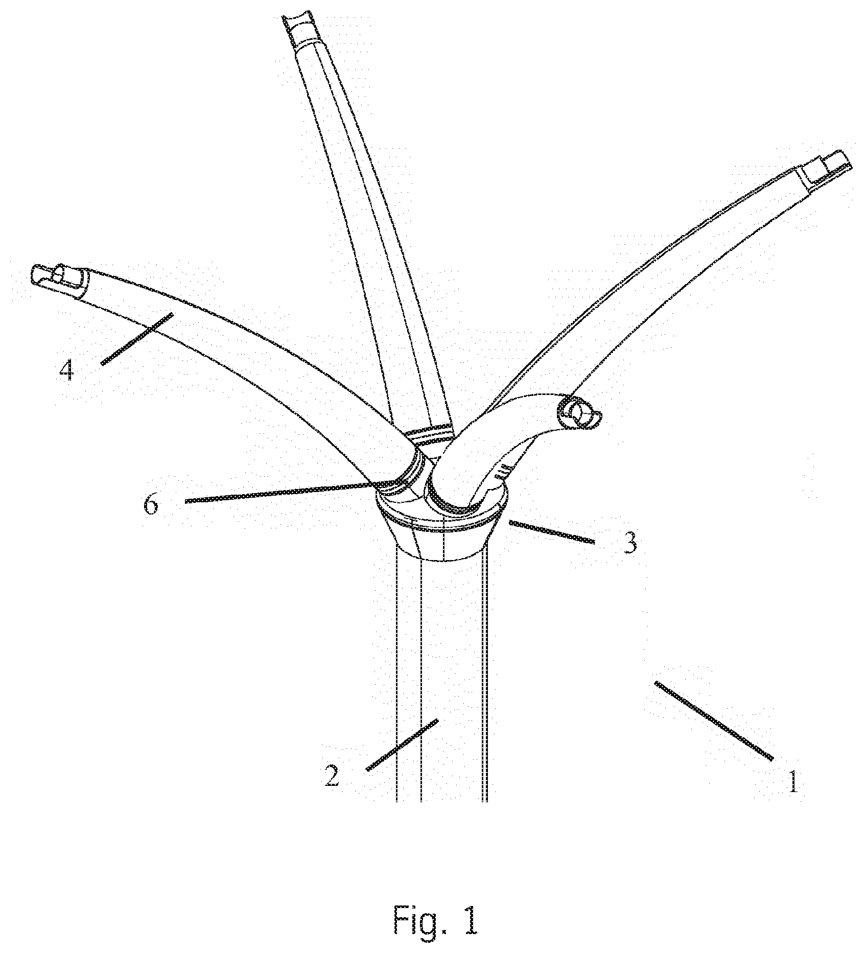
[0031] FIG. 1 shows a perspective view of a free pillar (1) according to the invention in an embodiment with four cantilever arms (4) which are conical in basic form and are lightly curved. Said cantilever arms (4) are connected by means of screw flanges (6) to the load-branching node (3) which is explained in more detail in the following figures. The load-branching node (3) connects to the upper end at the top of a shaft (2).
[0032] FIG. 2 shows a load-branching node (3) and parts of the cantilever arms (4) according to FIG. 1. In this connection, the cantilever arms (4) are each connected by means of screw flanges (6) to a cantilever arm connection (32), which cantilever arm connections are connected to a dome surface (31) which comprises a curvature upward. A transition (33) connects downwardly to the edge of the dome surface (31), the lateral surface of which transition tapers conically downward in the direction of the shaft (2) which is not shown.
[0033] FIG. 3 shows an alternative embodiment to the variant shown in FIG. 2. The design with regard to the cantilever arms (4) covering the screw flanges (6) and the cantilever arm connections (32) and the dome surface (31) are identical in this connection. However, the transition (33) comprises smaller diameters, which is why the transition (33) is not connected to the edge but to the inside of the dome surface (31). As a further difference, the transition (33) tapers in a conical manner to a smaller diameter compared to the shaft (2) which is not shown. In order to compensate for said difference in diameter, the transition (33) comprises a connection plate which connects to the cone.
[0034] FIG. 4 and FIG. 5 each show the lower components of different embodiments. Common to said embodiments is that the shaft (2) extends from bottom to top and a conical transition (33), which widens up to the diameter of the dome surface (31), is provided at the upper end. The dome surface (31) is realized in each case as a spherical segment. On account of the realization as spherical segments, it is possible to use tubular portions with a circular cross section for the cantilever arm connections (32) which are not shown.
[0035] The difference consists in that in FIG. 4 the dome surface (31) provides a hemisphere, consequently therefore the height of the spherical segment or of the dome surface (31) corresponds to the radius of the spherical segment. A relatively large dome surface (31) which correspondingly provides space for an arrangement for the cantilever arm connections (32) which are not shown and at the same time, in particular for large spans, enables a large run-out angle between cantilever arm connections (32) and center axis of the shaft (2), is provided as a result.
[0036] In contrast to this, in FIG. 5 the height of the spherical segment is smaller than the radius of the spherical segment. This forms a dome surface (31) which is realized in a significantly flatter manner, as a result of which a smaller run-out angle is generated between cantilever arm connection (32) and center axis of the shaft (2), which improves the flow of forces in the components.
[0037] FIG. 6 shows a shaft (2) of a pillar (1) according to the invention and the dome surface (31) connects in a direct manner to the upper end of said pillar. A transition (33) is not provided in said exemplary embodiment. Here the dome surface (31) comprises a design which is symmetrical to the plane which extends perpendicularly to the drawing plane through the center axis of the shaft (2) and is designed for two cantilever arm connections (32). As shown, the center axes of the cantilever arm connections (32) and of the shaft (2) meet at a point. The position of said point on the center axis of the shaft (2) can be modified in said exemplary embodiment by modifying the height of the triangular cross section of the dome surface (31) shown in the view and/or another angle of the surfaces on the cantilever arm connections (32) for connection to the dome surface (31), as a result of which the flow of forces in the pillar is modifiable.
[0038] FIG. 7 shows an exemplary use of pillars (1) according to the invention by way of a bridge as superstructure (5). In said example, the pillars (1) support the superstructure (5) as a result of a shaft (2) extending in each case from the ground upward and branching into the cantilever arms (4) at the load-branching node (3). The cantilever arms (4) branch out in order to enable a larger support surface or span and are connected to the superstructure (5).
[0039] The different features of the invention can be combined with one another in an arbitrary manner and are not restricted to just the examples of embodiments which are described or shown.
[0040] It should be understood that the mixing and matching of features, elements, methodologies and/or functions between various examples may be expressly contemplated herein so that one skilled in the art would appreciate from the present teachings that features, elements and/or functions of one example may be incorporated into another example as appropriate, unless described otherwise above.
LIST OF REFERENCES
[0041] 1 (Free) pillar
[0042] 2 Shaft
[0043] 3 Load-branching node
[0044] 31 Dome surface
[0045] 32 Cantilever arm connection
[0046] 33 Transition
[0047] 4 Cantilever arm
[0048] 5 Superstructure
[0049] 6 Screw flange
* * * * *
uspto.report is an independent third-party trademark research tool that is not affiliated, endorsed, or sponsored by the United States Patent and Trademark Office (USPTO) or any other governmental organization. The information provided by uspto.report is based on publicly available data at the time of writing and is intended for informational purposes only.
While we strive to provide accurate and up-to-date information, we do not guarantee the accuracy, completeness, reliability, or suitability of the information displayed on this site. The use of this site is at your own risk. Any reliance you place on such information is therefore strictly at your own risk.
All official trademark data, including owner information, should be verified by visiting the official USPTO website at www.uspto.gov. This site is not intended to replace professional legal advice and should not be used as a substitute for consulting with a legal professional who is knowledgeable about trademark law.