Stackable Display Containers
Pohlman; Christopher John ; et al.
U.S. patent application number 16/003738 was filed with the patent office on 2019-12-12 for stackable display containers. This patent application is currently assigned to Inline Plastics Corp.. The applicant listed for this patent is Inline Plastics Corp.. Invention is credited to Carrie Cline, Nicholas Baron Ivanoff, Victor Ivenitsky, Christopher John Pohlman.
| Application Number | 20190375579 16/003738 |
| Document ID | / |
| Family ID | 68765657 |
| Filed Date | 2019-12-12 |


View All Diagrams
| United States Patent Application | 20190375579 |
| Kind Code | A1 |
| Pohlman; Christopher John ; et al. | December 12, 2019 |
Stackable Display Containers
Abstract
Disclosed are display containers (e.g., for packaging food items). Certain embodiments of the container are stackable and include a cover portion of the container having a non-flat presentation surface, and one or more stacking recesses defined between the non-flat presentation surface and at least one of the one or more cover body sides. A base portion of the container can include a mating surface shaped to mate with a portion of the non-flat presentation surface when stacked on a corresponding bottom container such that an inside of the corresponding bottom container can be viewed through the non-flat presentation surface of the bottom container. The base body can include one or more stacking feet extending from the base body and configured to insert into the one or more stacking recesses when stacked on the cover portion of the corresponding bottom container such that the one or more stacking feet engage the cover portion.
| Inventors: | Pohlman; Christopher John; (West Haven, CT) ; Ivenitsky; Victor; (South Salem, NY) ; Ivanoff; Nicholas Baron; (Ansonia, CT) ; Cline; Carrie; (Milford, CT) | ||||||||||
| Applicant: |
|
||||||||||
|---|---|---|---|---|---|---|---|---|---|---|---|
| Assignee: | Inline Plastics Corp. Shelton CT |
||||||||||
| Family ID: | 68765657 | ||||||||||
| Appl. No.: | 16/003738 | ||||||||||
| Filed: | June 8, 2018 |
| Current U.S. Class: | 1/1 |
| Current CPC Class: | B65D 2543/00027 20130101; B65D 2401/05 20200501; B65D 2543/00796 20130101; B65D 2543/00731 20130101; B65D 43/16 20130101; B65D 21/0223 20130101; B65D 2543/0062 20130101; B65D 2543/00194 20130101; B65D 2543/00296 20130101; B65D 2543/00685 20130101; B65D 2543/00351 20130101; B65D 2543/00324 20130101; B65D 43/162 20130101; B65D 2543/00509 20130101; B65D 5/005 20130101; B65D 85/62 20130101; B65D 2401/60 20200501; B65D 2543/00842 20130101; B65D 2543/00101 20130101 |
| International Class: | B65D 85/62 20060101 B65D085/62; B65D 5/00 20060101 B65D005/00; B65D 21/02 20060101 B65D021/02; B65D 43/16 20060101 B65D043/16 |
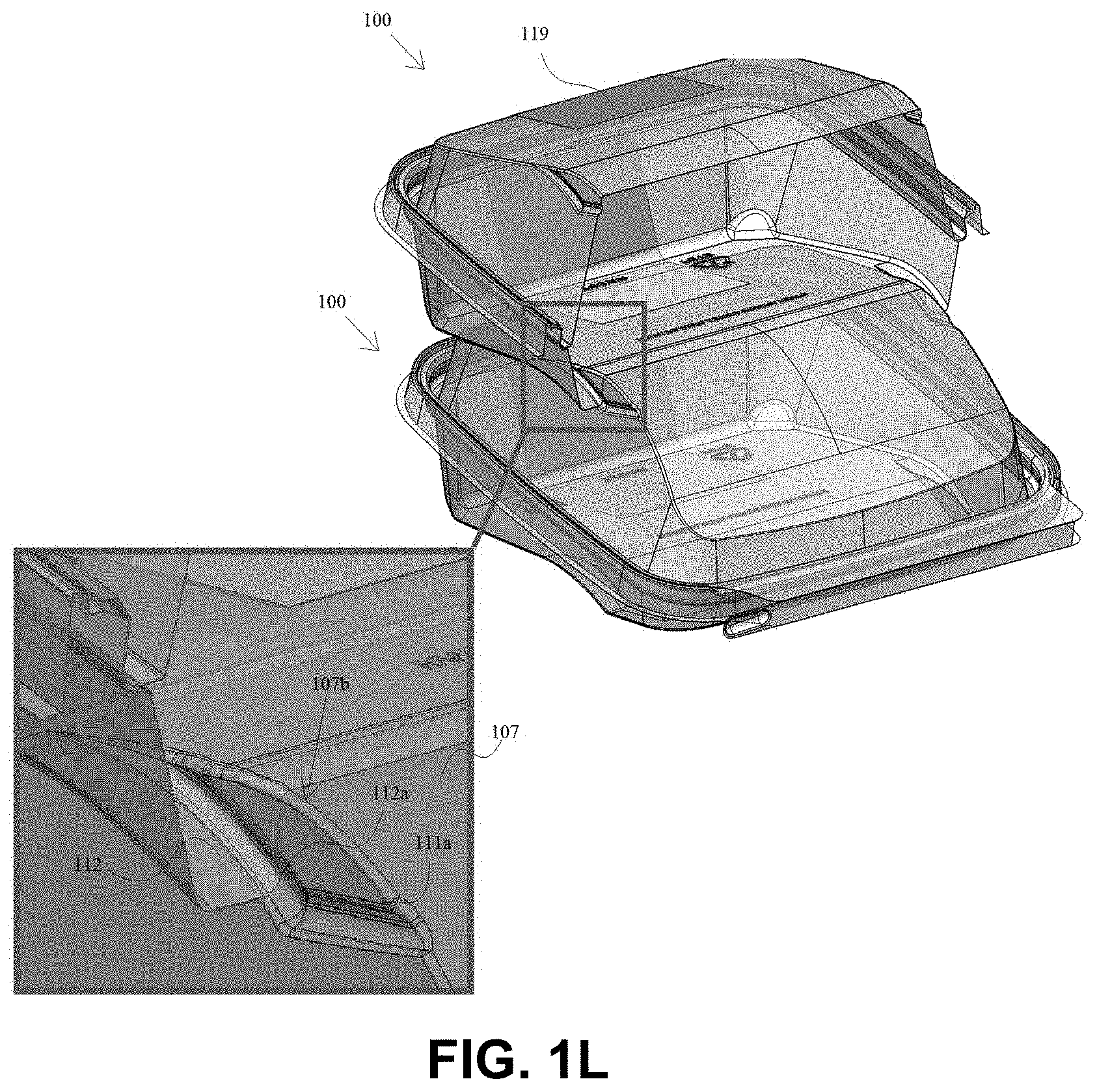
Claims
1. A stackable display container, comprising: (a) a cover portion including a cover sealing interface and a cover body extending from the cover sealing interface, the cover body having: (i) a non-flat presentation surface; (ii) one or more cover body sides connecting the non-flat presentation surface to the cover sealing interface; and (iii) one or more stacking recesses defined in the container body; and (b) a base portion including a base sealing interface configured to mate with the cover sealing interface, and a base body extending from the base sealing interface, the base body having: (i) a mating surface shaped to mate with a first portion of the non-flat presentation surface of the cover portion such that when a second corresponding container is stacked upon the container, an inside of the container can be viewed through a second portion of the non-flat presentation surface; (ii) one or more base body sides connecting the mating surface to the base sealing interface; and (iii) one or more stacking feet extending from the base body and arranged and configured to insert into the one or more stacking recesses of the second corresponding container when the container is stacked on the second corresponding container.
2. The container of claim 1, wherein a sitting contact plane is defined by contact points of the base portion when sitting on a flat surface, wherein a lip plane is defined by the base sealing interface, and wherein the base body defines a deep portion and a shallow portion such that the sitting contact plane and the lip plane are non-parallel such that the base sealing interface is angled forward when the base body is resting on a flat surface, which angles the cover body forward when the cover sealing interface and the base sealing interface are mated.
3. The container of claim 2, further comprising a living hinge connecting the cover portion to the base portion.
4. The container of claim 3, wherein the living hinge includes at least one score line or line of weakness.
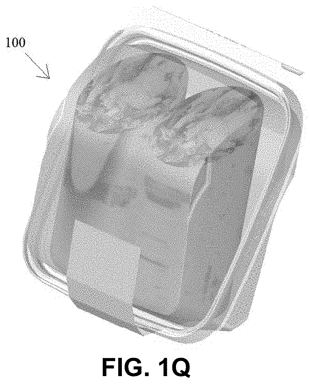
5. The container of claim 1, wherein the mating surface is shaped to mate flushly with the first portion of the non-flat presentation surface.
6. The container of claim 1, wherein the one or more recesses includes two or more grooves defined on opposite cover body sides, and the stacking feet include two or more stacking feet.
7. The container of claim 6, wherein the non-flat presentation surface includes a curved portion defining a peak and a flat portion extending from the curved portion, wherein the grooves are defined at the peak.
8. The container of claim 7, wherein the two or more stacking feet each include an inwardly extending ridge that snap fits and/or locks with each groove.
9. The container of claim 1, wherein the one or more recesses includes two or more recesses, wherein each recess is defined on a corner of the cover body such that the two or more recesses wrap around a respective corner, and wherein each of the stacking feet are defined at a corner of the base body.
10. The container of claim 1, one or more stacking recesses are defined between the non-flat presentation surface and at least one of the one or more cover body sides.
11. A display container, comprising: (a) a cover portion including a cover sealing interface and a cover body extending from the cover sealing interface, the cover body having: (i) a non-flat presentation surface; (ii) one or more cover body sides connecting the non-flat presentation surface to the cover sealing interface; (b) a base portion including a base sealing interface configured to mate with the cover sealing interface, and a base body extending from the base sealing interface, the base body having: (i) a mating surface shaped to mate with a first portion of the non-flat presentation surface of the cover portion such that when a second corresponding container is stacked upon the container, an inside of the container can be viewed through a second portion of the non-flat presentation surface; (ii) one or more base body sides connecting the mating surface to the base sealing interface; and wherein the base body defines a deep portion and a shallow portion such that a sitting contact plane, defined by contact points of the base portion when sitting on a flat surface, and a lip plane defined by the base sealing interface are non-parallel such that the base sealing interface is angled forward when the base body is resting on a flat surface, which angles the cover body forward when the cover sealing interface and the base sealing interface are mated to present the presentation surface and to allow viewing of the inside of the container when stacked; and (c) a living hinge connecting the cover portion to the base portion, wherein the living hinge is defined adjacent the shallow portion of the base portion along at least a partial width of the cover sealing interface and base sealing interface.
12. The container of claim 11, wherein the living hinge includes at least one score line or line of weakness.
13. The container of claim 11, wherein the mating surface is shaped to mate flushly with the first portion of the non-flat presentation surface.
14. The container of claim 11, further comprising: one or more stacking recesses defined in the container body, and one or more stacking feet extending from the base body and arranged and configured to insert into the one or more stacking recesses of the second corresponding container when the container is stacked on the second corresponding container.
15. The container of claim 14, wherein the one or more recesses includes two or more grooves defined on opposite cover body sides, and the stacking feet include two or more stacking feet.
16. The container of claim 15, wherein the non-flat presentation surface includes a curved portion defining a peak and a flat portion extending from the curved portion, wherein the grooves are defined at the peak.
17. The container of claim 16, wherein the two or more stacking feet each include an inwardly extending ridge that snap fits and/or locks with each groove.
18. The container of claim 14, wherein the one or more recesses includes two or more recesses, wherein each recess is defined on a corner of the cover body such that the two or more recesses wrap around a respective corner, and wherein each of the stacking feet are defined at a corner of the base body.
19. The container of claim 14, wherein the one or more recesses include a single recess, and the one or more stacking feet include a single stacking foot.
20. The container of claim 11, wherein the container is configured to be stable in two positions.
Description
BACKGROUND OF THE DISCLOSURE
1. Field of the Disclosure
[0001] This disclosure generally relates to containers, e.g., for food items, and more particularly to plastic containers that are adapted and configured to be displayed in a stacked arrangement.
2. Background of the Related Art
[0002] Traditional containers, e.g., for food items sold at stores, are limited in their ability to display the contents therein while being stacked. Moreover, existing containers are unstable if stacked on an angled shelf, e.g., as in certain sandwich containers, and also risk damaging the label when stacked. Improved containers are desired.
SUMMARY OF THE DISCLOSURE
[0003] The purpose and advantages of one or more embodiments of this disclosure will be set forth in and apparent from the description that follows. Additional advantages of one or more embodiments of this disclosure will be realized and attained by the devices, systems and methods particularly pointed out in the written description and claims hereof, as well as from the appended drawings.
[0004] To achieve these and other advantages and in accordance with the purpose of one or more embodiments of this disclosure, as embodied, one or more embodiments include, in at least one aspect, a stackable display container (e.g., for packaging food items such as sandwiches). Certain embodiments of the container include a cover portion including a cover sealing interface and a cover body extending from the cover sealing interface. The cover body can include a non-flat presentation surface, one or more cover body sides connecting the non-flat presentation surface to the cover sealing interface, and one or more stacking recesses defined in the container body (e.g., between the non-flat presentation surface and at least one of the one or more cover body sides in certain embodiments).
[0005] A base portion can include a base sealing interface configured to mate with the cover sealing interface, and a base body extending from the base sealing interface. The base body can include a mating surface shaped to mate with the first portion of the non-flat presentation surface of the cover portion (e.g., such that when stacked on the second corresponding container, an inside of the second corresponding container can be viewed through the non-flat presentation surface of the second corresponding container). The base body can include one or more base body sides connecting the mating surface to the base sealing interface, and one or more stacking feet extending from the base body and arranged and configured to insert into the one or more stacking recesses of the second corresponding container when the container is stacked on the second corresponding container.
[0006] In certain embodiments, the base body can define a deep portion and a shallow portion such that a sitting contact plane (i.e., defined by contact points of the base portion when sitting on a flat surface) and a lip plane (e.g., defined by the base sealing interface) are non-parallel such that the base sealing interface is angled forward when the base body is resting on a flat surface. This, in turn, angles the cover body forward when the cover sealing interface and the base sealing interface are mated (e.g., to present the presentation surface and to allow viewing of the inside of the bottom container when stacked).
[0007] The container can include a living hinge connecting the cover portion to the base portion. In certain embodiments, the living hinge can include at least one score line or line of weakness.
[0008] The one or more recesses can include two or more grooves defined on opposite cover body sides, and the stacking feet can include two or more stacking feet. The non-flat presentation surface can include a curved portion defining a peak and a flat portion extending from the curved portion. The grooves can be defined at the peak. The two or more stacking feet can each include an inwardly extending ridge that snap fits and/or locks with each groove.
[0009] In certain embodiments, the one or more recesses can include two or more recesses. Each recess is defined on a corner of the cover body such that the two or more recesses wrap around a respective corner. In such embodiments, each of the stacking feet can be defined at a corner of the base body.
[0010] In certain embodiments, the one or more recesses include a single recess, and the one or more stacking feet include a single stacking foot.
[0011] The mating surface can be shaped to mate flushly with the presentation surface. Any other suitable shape is contemplated herein to allow stacking and viewing, for example.
[0012] In accordance with at least one aspect of this disclosure, a display container can include a cover portion of the container having a cover sealing interface and a cover body extending from the cover sealing interface, the cover body having a non-flat presentation surface, one or more cover body sides connecting the non-flat presentation surface to the cover sealing interface. The container can include a base portion of the container including a base sealing interface configured to mate with the cover sealing interface, and a base body extending from the base sealing interface, the base body having a mating surface shaped to mate with a portion of the non-flat presentation surface when stacked on a corresponding bottom container such that an inside of the corresponding bottom container can be viewed through the non-flat presentation surface of the bottom container, and one or more base body sides connecting the mating surface to the base sealing interface.
[0013] The base body can define a deep portion and a shallow portion such that a sitting contact plane, defined by contact points of the base portion when sitting on a flat surface, and a lip plane defined by the base sealing interface are non-parallel such that the base sealing interface is angled forward when the base body is resting on a flat surface, which angles the cover body forward when the cover sealing interface and the base sealing interface are mated to present the presentation surface and to allow viewing of the inside of the bottom container when stacked. A living hinge as described herein can connect the cover portion to the base portion. The living hinge can be defined adjacent the shallow portion of the base portion along at least a partial width of the cover sealing interface and base sealing interface.
[0014] In certain embodiments, the container can be configured to be stable in two positions (e.g., such that it can stand on a side or sit mating surface down). The container can include any other features and/or combinations thereof as disclosed herein or as appreciated by those having ordinary skill in the art.
BRIEF DESCRIPTION OF THE DRAWINGS
[0015] So that those having ordinary skill in the art to which the present invention pertains will more readily understand how to employ the subject of this disclosure, embodiments will be described in detail hereinbelow with reference to the drawings, wherein:
[0016] FIG. 1A illustrates a perspective view of an embodiment of a container that has been constructed in accordance with this disclosure, shown in a closed state and in a display orientation;
[0017] FIG. 1B illustrates a perspective view taken from below taken from below of the container embodiment of FIG. 1A, showing the base portion and in a closed state;
[0018] FIG. 1C illustrates a top down view of the container embodiment of FIG. 1A;
[0019] FIG. 1D illustrates a side elevation view of the container embodiment of FIG. 1A;
[0020] FIG. 1E illustrates a cross-sectional view of the container embodiment of FIG. 1C taken along cut line B-B;
[0021] FIG. 1F illustrates a perspective view of the container embodiment of FIG. 1A, shown in an open state;
[0022] FIG. 1G illustrates a top down view of the container embodiment of FIG. 1F;
[0023] FIG. 1H illustrates a side elevation view of the container embodiment of FIG. 1F;
[0024] FIG. 1I illustrates a cross-sectional view of the container embodiment of FIG. 1G taken along cut line A-A;
[0025] FIG. 1J illustrates two containers of the embodiment of FIG. 1A arranged in a stacked configuration, showing a first container stacked on a corresponding second container;
[0026] FIG. 1K illustrates an enlarged view of the embodiment of FIG. 1J, showing a stacking foot of the first container interlocking with a groove of the second container;
[0027] FIG. 1L illustrates a partial cross-section view of the embodiment of FIG. 1J, showing the first/top container sectioned and showing an enlarged view of the interlocking between the top container and the bottom container;
[0028] FIG. 1M illustrates a side elevation view of the embodiment of FIG. 1J, showing a label applied to each container;
[0029] FIG. 1N illustrates an enlarged view of the embodiment of FIG. 1M, showing how the labels thereof do not interfere with each other when the containers are stacked;
[0030] FIG. 1O illustrates a perspective view of the embodiment of FIG. 1J, showing the containers having a sandwich wrap disposed therein which illustrates the presentation of an item within the containers;
[0031] FIG. 1P illustrates a perspective view of the embodiment of FIG. 1A, shown having an item of food therein and in a sitting position;
[0032] FIG. 1Q illustrates a perspective view of the embodiment of FIG. 1A, shown having an item of food therein and in a standing position;
[0033] FIG. 2A illustrates a perspective view of another embodiment that has been constructed in accordance with this disclosure, shown having a label disposed thereon;
[0034] FIG. 2B illustrates a perspective view taken from below of the container embodiment of FIG. 2A, showing the base portion and in a closed state;
[0035] FIG. 2C illustrates a top down view of the container embodiment of FIG. 2A;
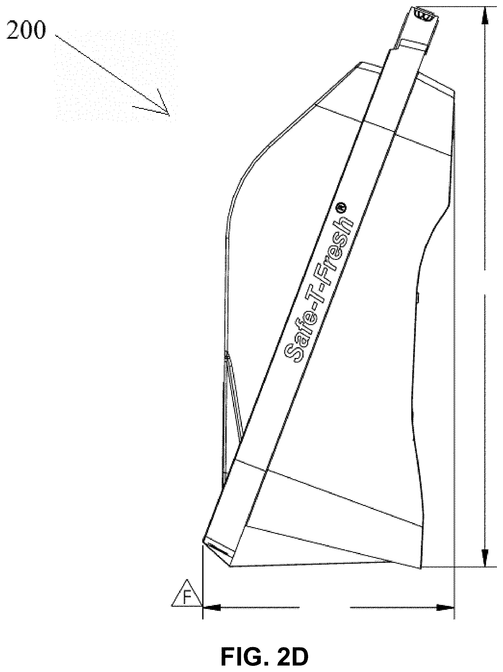
[0036] FIG. 2D illustrates a side elevation view of the container embodiment of FIG. 2A;
[0037] FIG. 2E illustrates a cross-sectional view of the container embodiment of FIG. 2C taken along cut line A-A;
[0038] FIG. 2F illustrates a perspective view of the container embodiment of FIG. 2A, shown in an open state;
[0039] FIG. 2G illustrates a top down view of the container embodiment of FIG. 2F;
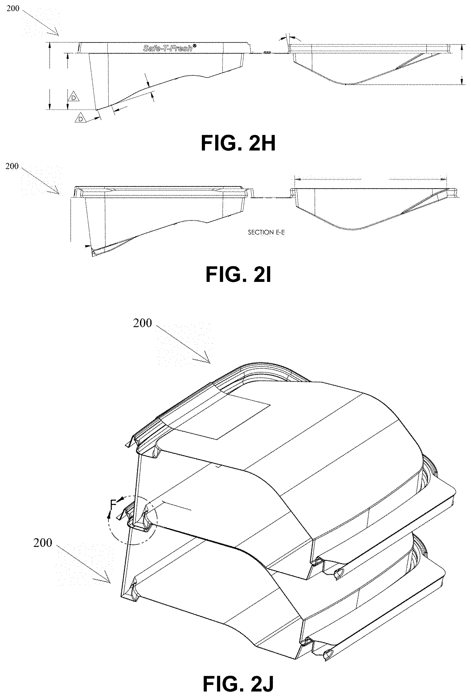
[0040] FIG. 2H illustrates a side elevation view of the container embodiment of FIG. 2F;
[0041] FIG. 2I illustrates a cross-sectional view of the container embodiment of FIG. 2G taken along cut line E-E;
[0042] FIG. 2J illustrates perspective, partial cross-sectional view of two containers of the container embodiment of FIG. 2A arranged in a stacked configuration, showing a first container stacked on a corresponding second container;
[0043] FIG. 2K illustrates an enlarged view of the container embodiment of FIG. 2J, showing a stacking foot of the first container interlocking with an recess of the second container;
[0044] FIG. 2L illustrates a partial cross-section view of the container embodiment of FIG. 2J, showing the first/top container sectioned and showing an enlarged view of the interlocking between the first/top container and the second/bottom container;
[0045] FIG. 2M illustrates a side elevation view of the container embodiment of FIG. 2J, showing a label applied to each container;
[0046] FIG. 2N illustrates a perspective and zoomed view of the container embodiment of FIG. 2M, showing how the labels thereof do not interfere with each other when the containers are stacked;
[0047] FIG. 2O illustrates a perspective view of the stacked container embodiments of FIG. 2J;
[0048] FIG. 2P illustrates a perspective view of the container embodiment of FIG. 2A, shown in a sitting position and stacked;
[0049] FIG. 2Q illustrates a perspective view of the container embodiment of FIG. 2A, shown in a standing position;
[0050] FIG. 3A illustrates a perspective view of another embodiment that has been constructed in accordance with this disclosure, shown having a label disposed thereon;
[0051] FIG. 3B illustrates a perspective view taken from below of the container embodiment of FIG. 3A, showing the base portion and in a closed state;
[0052] FIG. 3C illustrates a top down view of the container embodiment of FIG. 3A;
[0053] FIG. 3D illustrates a side elevation view of the container embodiment of FIG. 3A;
[0054] FIG. 3E illustrates a cross-sectional view of the container embodiment of FIG. 3C taken along cut line A-A;
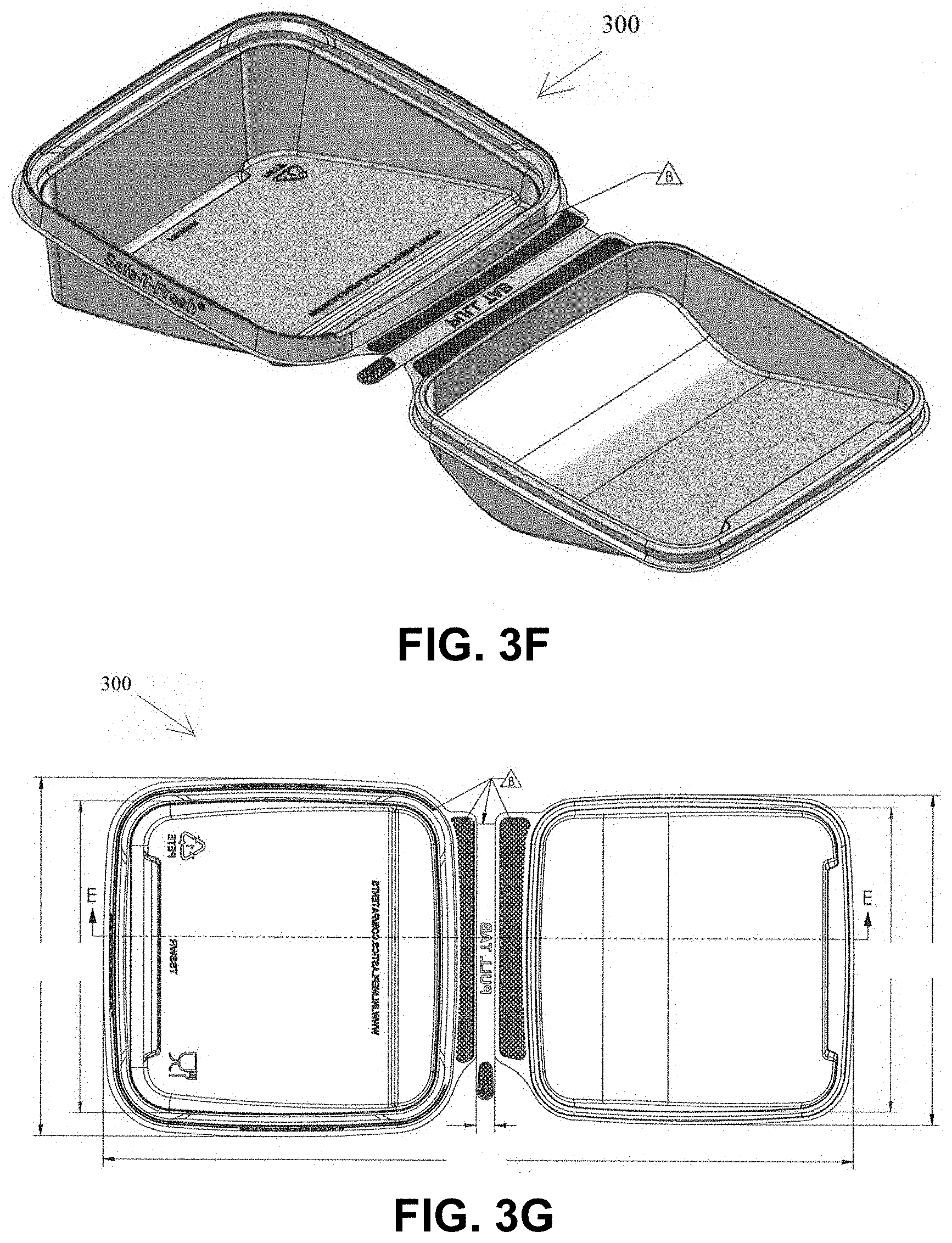
[0055] FIG. 3F illustrates a perspective view of the container embodiment of FIG. 3A, shown in an open state;
[0056] FIG. 3G illustrates a top down view of the container embodiment of FIG. 3F;
[0057] FIG. 3H illustrates a side elevation view of the container embodiment of FIG. 3F;
[0058] FIG. 3I illustrates a cross-sectional view of the container embodiment of FIG. 3G taken along cut line E-E;
[0059] FIG. 3J illustrates cross-sectional view of two containers of the container embodiment of FIG. 3A arranged in a stacked configuration, showing a first container stacked on a corresponding second container;
[0060] FIG. 3K illustrates an enlarged view of the container embodiment of FIG. 3J, showing a stacking foot of the first container interlocking with an recess of the second container;
[0061] FIG. 3L illustrates a partial cross-section view of the container embodiment of FIG. 3J, showing the first/top container sectioned and showing an enlarged view of the interlocking between the first container and the second/bottom container;
[0062] FIG. 3M illustrates a side elevation view of the container embodiment of FIG. 3J;
[0063] FIG. 3N illustrates a perspective and zoomed view of the container embodiment of FIG. 3M, showing interlocking of the top and second containers;
[0064] FIG. 3O illustrates a perspective view of the stacked container embodiments of FIG. 3J;
[0065] FIG. 3P illustrates a perspective view of the container embodiment of FIG. 3A, shown in a sitting position and stacked;
[0066] FIG. 3Q illustrates a perspective view of the container embodiment of FIG. 3A, shown in a standing position;
[0067] FIG. 4A illustrates a perspective view of an embodiment of a container in accordance with this disclosure;
[0068] FIG. 4B illustrates a side elevation view of the container embodiment of FIG. 4A;
[0069] FIG. 4C illustrates a front elevation view of the container embodiment of FIG. 4A;
[0070] FIG. 4D illustrates a rear elevation view of the container embodiment of FIG. 4A;
[0071] FIG. 4E illustrates a bottom plan view of the container embodiment of FIG. 4A;
[0072] FIG. 4F illustrates a perspective view of the container embodiment of FIG. 4A, shown open;
[0073] FIG. 4G illustrates a top down plan view of the container embodiment of FIG. 4F;
[0074] FIG. 4H illustrates a bottom up plan view of the container embodiment of FIG. 4F;
[0075] FIG. 4I illustrates a rear elevation view of the container embodiment of FIG. 4F;
[0076] FIG. 4J illustrates a left side elevation view of the container embodiment of FIG. 4F;
[0077] FIG. 4K illustrates a front elevation view of the container embodiment of FIG. 4F;
[0078] FIG. 4L illustrates a right side elevation view of the container embodiment of FIG. 4F;
[0079] FIG. 4M illustrates a perspective view two of the container embodiment of FIG. 4A, shown having an item of food therein and in a sitting position on the right and in the standing position on the left;
[0080] These and other aspects of the subject disclosure will become more readily apparent to those having ordinary skill in the art from the following detailed description of one or more embodiments of this disclosure taken in conjunction with the drawings.
DETAILED DESCRIPTION OF CERTAIN EMBODIMENTS
[0081] Embodiments of this disclosure are now described more fully with reference to the accompanying drawings, in which illustrated embodiments are shown. This disclosure is not limited in any way to the illustrated embodiments as the description below is merely provides exemplary embodiments in various forms, as appreciated by one skilled in the art. Therefore, it is to be understood that any structural and functional details disclosed herein are not to be interpreted as limiting, but merely as a basis for the claims and as a representative for teaching one skilled in the art to variously employ the embodiments disclosed herein. Furthermore, the terms and phrases used herein are not intended to be limiting but rather to provide an understandable description of the embodiments herein.
[0082] The present disclosure generally relates to containers (e.g., for packaging food items). Certain non-limiting embodiments of containers are described herein. Turning now descriptively to the drawings, in which similar reference characters denote similar elements throughout the several views, FIGS. 1A-1Q depict an embodiment of a stackable display container (e.g., for packaging food items). FIGS. 2A-2Q depict another embodiment of a stackable display container (e.g., for packaging food items). FIGS. 3A-3Q depict another embodiment of a stackable display container (e.g., for packaging food items). FIGS. 4A-4M depict another embodiment of a display container (e.g., for packaging food items).
[0083] While certain drawings are shown as opaque, the embodiments described herein are at least partially clear and opaque drawings are intended for clarity to show various features of the embodiments. However, it is contemplated that any suitable material (e.g., plastic) having any suitable properties (e.g., opaque, partially opaque, completely clear) can be used as appreciated by those having ordinary skill in the art.
[0084] While certain drawings may indicate certain example dimensions, any suitable dimensions for embodiments described herein or otherwise are contemplated herein. The example dimensions shown may be in inches or any other suitable scale. Any angles shown in the drawings are also for example only and any suitable angles depicted can be changed to any other suitable angle.
[0085] Also, while certain drawings may show indicia on or formed as part of embodiments of a container, any indicia is merely an example and any indicia need not be included, can be added, or can be changed in any suitable manner. Moreover, any shown use of a trademark (e.g., the term Safe-T-Fresh.RTM.) is as an indicator of source (namely the applicant) and is not to be construed that the mark is descriptive of the goods shown. All rights in any trademarks are reserved.
[0086] Referring generally to FIGS. 1A-1Q, with attention to FIG. 1A, the container 100 can include a cover portion 101 of the container 100 including a cover sealing interface 103 and a cover body 105 extending from the cover sealing interface 103. The cover body 105 can include a non-flat presentation surface 107 and one or more cover body sides 109a, b, c, d connecting (e.g., integrally) the non-flat presentation surface 107 to the cover sealing interface 103. In certain embodiments, the non-flat presentation surface 107 is continuous such that the non-flat presentation surface 107 does not include an edge (e.g., except where the non-flat presentation surface 107 meets the cover body sides 109a, b, c, d).
[0087] While embodiments shown include one or more cover body sides 109a, b, c, d, delineated by an edge, it is contemplated that one or more (e.g., all) of the sides 109a, b, c, d may be smoothly connected to and/or part of the presentation surface 107 such that the non-flat presentation surface 107 is a continuous surface to the cover sealing interface 103. For example, the front side 109c can be a smooth extension of the non-flat presentation surface 107 instead of having an edge as shown. In certain embodiments, the lateral sides 109a, 109b can be a smooth, laterally angled extension of the non-flat presentation surface 107. Also, as shown, the one or more cover sides 109a, b, c, d can be smoothly connected in any suitable manner (e.g., via rounded corners).
[0088] Certain embodiments can include one or more stacking recesses defined in the cover portion. For example, the container 100 can include one or more stacking recesses 111 defined between the non-flat presentation surface 107 and at least one of the one or more cover body sides 109a, b, c, d. For example, the one or more stacking recesses 111 can be defined at one or more edges between the non-flat presentation surface 107 and the cover body 109a, b, c, d.
[0089] A base portion 102 of the container 100 can include a base sealing interface 104 configured to mate with the cover sealing interface 103, and a base body 106 extending from the base sealing interface 104. In certain embodiments, the base sealing interface 104 can be larger than the cover sealing interface 103 to allow the cover sealing interface 103 to be inserted within the base sealing interface 104, or vice versa, to allow closure of the container. In certain embodiments, the base sealing interface 104 and the cover sealing interface 103 can include one or more interlocking features (e.g., one or more ridges to allow the base sealing interface 104 and the cover sealing interface 103 to removably interlock) as appreciated by those having ordinary skill in the art. The base sealing interface 104 and the cover sealing interface 103 can be shaped and configured to form a seal (e.g., a substantially air tight seal for food storage).
[0090] As shown in FIG. 1B, the base body 106 can include a mating surface 108 shaped to mate (e.g., flushly or otherwise) with a first portion (e.g., portion 107c) of the non-flat presentation surface 107 such that when a second corresponding container 100 is stacked upon the container 100, an inside of the container can be viewed through a second portion (e.g., portion 107a) of the non-flat presentation surface as shown in FIGS. 1J-1O). In certain embodiments, the shape of the mating surface is the same shape as a corresponding portion of the presentation surface 107. The shape of the mating surface 108 can be configured to allow an inside of a corresponding bottom container 100 to be viewed through the non-flat presentation surface 107 of the bottom container (e.g., as shown in FIG. 1O). In this regard, when stacked, a consumer can see an item within the container without having to remove the top container, for example.
[0091] The base body 106 can include one or more base body sides 110a, b, c, d connecting the mating surface 108 to the base sealing interface 104 (e.g., integrally). While embodiments shown include one or more base body sides 110a, b, c, d, delineated by an edge, it is contemplated that one or more (e.g., all) of the sides 110a, b, c, d may be smoothly connected to and/or part of the mating surface 108 such that the mating surface 108 is a continuous surface to the base sealing interface 104. For example, the base body front side 110c and/or rear side 110d can be a smooth extension of the mating surface 108 instead of having an edge as shown. In certain embodiments, the base body lateral sides 110a, 110b can be a smooth, laterally angled extension of the mating surface 108. Also, as shown, the one or more base body sides 110a, b, c, d can be smoothly connected in any suitable manner (e.g., via rounded corners).
[0092] Referring additionally to FIGS. 1C-1E, the base portion 102 can also include one or more stacking feet 112 extending from the base body 106 and arranged and configured to insert into the one or more stacking recesses 111 of the second corresponding container 100 when the container 100 is stacked on the second corresponding container 100 (e.g., such that the one or more stacking feet 112 engage the cover portion 101 to provide support in at least one direction to prevent relative movement between the top container and the bottom container). As shown, the stacking feet 112 can be a flush extension of the one or more base body sides 110a, b. In certain embodiments, such as that shown in FIGS. 1A-1Q, the stacking feet can extend from the base body 106 where the mating face includes a curved section (e.g., which is shaped to mate with a curved section of the non-flat presentation surface 107), for example. Any other suitable location is contemplated herein.
[0093] As shown in the embodiment of FIGS. 1A-1Q, the one or more recesses 111 can include one or more grooves 111a (e.g., two defined on opposite cover body sides 109a, 109b). The one or more stacking feet 112 can include two or more stacking feet 112, e.g., at least one for each groove 111a. The stacking feet 112 can include one or more ridges 112a configured to fit at least partially within the grooves 111a to engage the stacking feet to the cover portion 101. For example, the two or more stacking feet 112 can each include an ridge 112a that corresponds to the shape of the respective grooves 111a and can snap fit and/or lock with each groove 111a (e.g., as shown in FIGS. 1J, 1K, and 1L).
[0094] As shown, the grooves 111a and the ridges 112a can include a peaked shape. In certain embodiments, the grooves 111a and/or the ridges 112a can include a shape to allow the stacking feet 112 to be inserted (e.g., such as slid into the grooves 111a) or snapped in (e.g., by pushing the feet 112 down on the cover portion 101). For example, the material that forms container 100 can be a flexible plastic allowing elastic flexibility of the stacking feet 112.
[0095] In certain embodiments, the non-flat presentation surface 107 can include a curved portion 107a defining a peak 107b. In certain embodiments, the non-flat presentation surface 107 can also include a flat portion 107c extending from the curved portion 107a. The grooves 111a can be defined at the peak 107b, for example, as shown.
[0096] Referring to FIG. 1F-1I, in certain embodiments, the base body 106 can define a deep portion 106a and a shallow portion 106b such that a sitting contact plane 114 (i.e., defined by contact points of the base portion 102 when sitting on a flat surface) and a lip plane 116 (e.g., defined by the base sealing interface 104 such as the plane of the opening of the base portion 102) are non-parallel such that the base sealing interface 104 is angled forward when the base body 106 is resting on a flat surface. Referring to FIGS. 1M-1O, this, in turn, angles the cover body 105 forward when the cover sealing interface 103 and the base sealing interface 104 are mated to present the presentation surface 107 and to allow viewing of the inside of the bottom container 100 when stacked.
[0097] The angle between the sitting contact plane 114 and the lip plane 116 can be the same as a display shelf, e.g., about 10 degrees, or any other suitable angle. In certain embodiments, as shown in FIG. 1M, the container 100 can be configured such that stacking a container 100 offsets its relative position backward (using the lip plane 114 line as depicted in FIG. 1H as an axis) such that the top container 100 does not completely overhang the bottom container 100. This can also position the center of gravity of a stack in a more favorable position for an angled shelf. The relative position of the top container 100 can be changed by changing the location of the stacking feet 112 and/or the shape/position of the mating surface 108.
[0098] The container 100 can include a living hinge 117 connecting the cover portion 101 to the base portion 102. In certain embodiments, the living hinge 117 can include at least one score line or line of weakness. For example, the living hinge can include a tamper resistant tear tab 117a that is configured to be torn off (e.g., at the score line or weakness) to destroy the living hinge 117 and separate the cover portion 101 and the base portion 102. As shown, the cover portion 101 and the base portion 102 can include hinge extensions 117b, 117c, respectively, that attach to the tear tab 117a (e.g., via a perforated or weakened connection, or in any other suitable manner as appreciated by those having ordinary skill in the art). In certain embodiments, the living hinge 117 may be not removable or destroyable.
[0099] Referring to FIGS. 1M-1O, when closed, a label 119 can be adhered to the container 100, e.g., on the opposite side as the living hinge 117 as shown, to seal the cover portion 101 to the base portion 102. This can maintain a seal of the cover portion 101 and the base portion 102 and provide visual assurance to a consumer that the contents have not been tampered with when the hinge 117 and the label 119 are intact. Also, in certain embodiments, e.g., as shown in FIGS. 1A-1Q, the containers 100 are configured to prevent label interference such that the labels 119 do not touch each other when containers are stacked, e.g., as shown in FIG. 1N.
[0100] Referring to FIGS. 1P and 1Q, the base portion 101 can be shaped to allow for two or more stable positions. For example, as shown in FIG. 1P, the container 100 can be stable in a sitting position which angles the base sealing interface 104 (and thus the cover portion 101) forward. As shown in FIG. 1O, the container 100 can be stable in at least one standing position, e.g., resting on the rear side 110d of the base body 106 and the base sealing interface 104.
[0101] The recesses and/or stacking feet as described herein can include any suitable shape and location. For example, referring now to FIGS. 2A-2Q, the embodiment of a container 200 shown can include similar features as the embodiment of FIGS. 1A-1Q as described above, however, the location and shape of the one or more recesses 211 and the one or more stacking feet 212 are different, for example.
[0102] As shown in FIGS. 2A and 2B, in certain embodiments, the one or more recesses 211 can include two or more recesses 211. Each recess 211 can be defined on a corner 205a of the cover body 205 such that the two or more recesses wrap around a respective corner 205a. In such embodiments, each of the stacking feet 212 can be defined at a corner 206a of the base body 206 and can include a similar wrap around shape. Such an embodiment can provide stability in three directions, e.g., each sideways direction and the forward direction.
[0103] Referring now to FIGS. 3A-3Q, the embodiment of a container 300 shown can include similar features as the embodiment of FIGS. 1A-1Q as described above, however, the location and shape of the one or more recesses 311 and the one or more stacking feet 312 differ. For example, in certain embodiments, the one or more recesses 311 can include a single recess 311 defined in a rear portion of the cover body 305, and the one or more stacking feet 312 include a single stacking foot 312. The stacking recess 311 can include a channel shaped recess defined by a rear portion of the base body 306. The stacking foot 312 can include a bar shape, for example, and can be dimensioned to fit in the stacking recess 312 snugly or loosely in any suitable manner. Such a stacking foot can provide at least three directions of stability, e.g., as described above with respect to the embodiment of FIGS. 2A-2Q.
[0104] FIGS. 4A-4M illustrate another embodiment of a container 400 that can include similar features as the above described embodiments, without specific stacking features or recesses. However, certain embodiments, e.g., as shown, can still be stacked without such features to prevent relative movement (on an angled or flat shelf). Also, such an embodiment can be placed in at least two stable positions, e.g., as shown in FIG. 4M and described above.
[0105] As shown, each embodiment can be configured to be stable in two positions (e.g., such that it can stand on a side or sit mating surface down). However, it is contemplated that the containers 100, 200, 300 can be configured to only be stable in the sitting position.
[0106] Embodiments include tamper evident plastic sandwich wrap containers that enhances food presentation for, e.g., wedges, hoagies, wraps, and/or sandwiches with multiple ways of presenting in the market place while increasing shelf space efficiency by allowing multiple containers to be stacked. Embodiments allow stackability even when using a "wrap-around" label due to embodiments preventing label interaction.
[0107] Certain embodiments allow a panoramic viewing window curve, e.g., to the lip, which allows food to present itself. Certain embodiments reflect that profile curve on the cover portion to the base portion, which provides complementary curves that function as alignment and balance when stacked. Embodiments stack using grooves that provide an interlocking relationship that utilizes undercuts and, e.g., a bead shaped rib. In certain embodiments, due to the stacking feature being closer to the side walls, e.g., and only coming in about 0.50'' on the base portion, no interference with the label can occur to jeopardize the product or package.
[0108] Traditional tamper evident container design, e.g., for sandwiches, hoagies, and wraps are not properly stackable and/or stable, and do not display the item in the container with a panoramic window. Embodiments can be stacked, e.g., two high while presenting on a shelf that is angled, e.g., about 10 degrees, without sliding off the shelf or one another.
[0109] Where a range of values is provided, it is understood that each intervening value, to the tenth of the unit of the lower limit unless the context clearly dictates otherwise, between the upper and lower limit of that range and any other stated or intervening value in that stated range is encompassed within this disclosure. The upper and lower limits of these smaller ranges may independently be included in the smaller ranges is also encompassed within this disclosure, subject to any specifically excluded limit in the stated range. Where the stated range includes one or both of the limits, ranges excluding either both of those included limits are also included in this disclosure.
[0110] Unless defined otherwise, all technical and scientific terms used herein have the same meaning as commonly understood by one of ordinary skill in the art to which this disclosure belongs. Although any methods and materials similar or equivalent to those described herein can also be used in the practice or testing of the disclosed embodiments, exemplary methods and materials are now described. All publications mentioned herein are incorporated herein by reference to disclose and describe the methods and/or materials in connection with which the publications are cited.
[0111] It must be noted that as used herein and in the appended claims, the singular forms "a", "an," and "the" include plural referents unless the context clearly dictates otherwise. Thus, for example, reference to "a stimulus" includes a plurality of such stimuli and reference to "the signal" includes reference to one or more signals and equivalents thereof known to those skilled in the art, and so forth.
[0112] Any suitable combination(s) of any disclosed embodiments and/or any suitable portion(s) thereof are contemplated herein as appreciated by those having ordinary skill in the art.
[0113] Those having ordinary skill in the art understand that any numerical values disclosed herein can be exact values or can be values within a range. Further, any terms of approximation (e.g., "about", "approximately", "around") used in this disclosure can mean the stated value within a range. For example, in certain embodiments, the range can be within (plus or minus) 20%, or within 10%, or within 5%, or within 2%, or within any other suitable percentage or number as appreciated by those having ordinary skill in the art (e.g., for known tolerance limits or error ranges).
[0114] The descriptions above and the accompanying drawings should be interpreted in the illustrative and not the limited sense. While this disclosure has been disclosed in connection with the embodiments disclosed herein, it should be understood that there may be other embodiments which fall within the scope of this disclosure and the following claims. Where a claim, if any, is expressed as a means or step for performing a specified function, it is intended that such claim be construed to cover the corresponding structure, material, or acts described in the specification and equivalents thereof, including both structural equivalents and equivalent structures, material-based equivalents and equivalent materials, and act-based equivalents and equivalent acts.
* * * * *
D00000
D00001
D00002
D00003
D00004
D00005
D00006
D00007
D00008
D00009
D00010
D00011
D00012

D00013
D00014

D00015

D00016

D00017
D00018

D00019

D00020
D00021

D00022

D00023

D00024

D00025

D00026

D00027

D00028

D00029

D00030

D00031

D00032

D00033
D00034

D00035

D00036

D00037

D00038

D00039

D00040

D00041

D00042

D00043

D00044

D00045

D00046

D00047

D00048

XML
uspto.report is an independent third-party trademark research tool that is not affiliated, endorsed, or sponsored by the United States Patent and Trademark Office (USPTO) or any other governmental organization. The information provided by uspto.report is based on publicly available data at the time of writing and is intended for informational purposes only.
While we strive to provide accurate and up-to-date information, we do not guarantee the accuracy, completeness, reliability, or suitability of the information displayed on this site. The use of this site is at your own risk. Any reliance you place on such information is therefore strictly at your own risk.
All official trademark data, including owner information, should be verified by visiting the official USPTO website at www.uspto.gov. This site is not intended to replace professional legal advice and should not be used as a substitute for consulting with a legal professional who is knowledgeable about trademark law.