Setting device
Lebeau; Andreas ; et al.
U.S. patent application number 16/436214 was filed with the patent office on 2019-12-12 for setting device. The applicant listed for this patent is PROFIL Verbindungstechnik GmbH & Co. KG. Invention is credited to Klaus Irmler, Andreas Lebeau, Benjamin Lesky.
| Application Number | 20190374997 16/436214 |
| Document ID | / |
| Family ID | 66752000 |
| Filed Date | 2019-12-12 |


View All Diagrams
| United States Patent Application | 20190374997 |
| Kind Code | A1 |
| Lebeau; Andreas ; et al. | December 12, 2019 |
Setting device
Abstract
The present invention relates to a setting device for fastening an element to a workpiece having a guide device that can be brought into mechanical contact with the element and that has an axial hollow space for guiding the element, and having an axially movable ram for moving the element in a setting direction through the hollow space of the guide device, wherein the guide device has at least one first and one second guide element; wherein the guide elements bound the axial hollow space and are preloaded by means of a preloading device by a preloading force acting radially inwardly on the guide element, and wherein a detection device is associated with the guide device and a presence, position and/or location of an element in the region of the guide device can be detected by it.
| Inventors: | Lebeau; Andreas; (Friedrichsdorf, DE) ; Irmler; Klaus; (Pohlheim, DE) ; Lesky; Benjamin; (Rosbach vor der Hohe, DE) | ||||||||||
| Applicant: |
|
||||||||||
|---|---|---|---|---|---|---|---|---|---|---|---|
| Family ID: | 66752000 | ||||||||||
| Appl. No.: | 16/436214 | ||||||||||
| Filed: | June 10, 2019 |
| Current U.S. Class: | 1/1 |
| Current CPC Class: | B21J 15/28 20130101; B21J 9/02 20130101; B21J 15/42 20130101; B23P 19/062 20130101; B25B 23/10 20130101; B21J 15/025 20130101; B21J 9/10 20130101; B21J 15/16 20130101; B21J 15/32 20130101 |
| International Class: | B21J 15/28 20060101 B21J015/28; B21J 9/10 20060101 B21J009/10; B21J 9/02 20060101 B21J009/02; B21J 15/16 20060101 B21J015/16 |
Foreign Application Data
| Date | Code | Application Number |
|---|---|---|
| Jun 11, 2018 | DE | 102018113870.9 |
Claims
1. A setting device for fastening an element to a workpiece, the setting device comprising: a guide device that can be brought into mechanical contact with the element and that has an axial hollow space for guiding the element, and an axially movable ram for moving the element in a setting direction through the hollow space of the guide device, wherein the guide device has at least one first and one second guide element; wherein the first and second guide elements bound the axial hollow space and are preloaded by means of a preloading device by a preloading force acting radially inwardly on at least one guide element, and wherein a detection device is associated with the guide device and at least one of a presence, a position and a location of an element in the region of the guide device can be detected by the detection device.
2. The setting device in accordance with claim 1, wherein the detection device has at least one of an electrical principle of operation, an optical acoustic principle of operation, a magnetic acoustic principle of operation and an acoustic principle of operation and/or comprises at least one of a force sensor and a pressure sensor.
3. The setting device in accordance with claim 1, wherein the detection device is at least partly integrated in at least one of the guide elements; and wherein at least one measurement tap or sensor of the detection device is arranged in a region of action of the guide device, viewed in the setting direction.
4. The setting device in accordance with claim 1, wherein the detection device comprises a first contact element that is provided at an inner side of the first guide element and a second contact element that is provided at an inner side of the second guide element, with the contact elements being able to be brought at least sectionally into contact with the element on the movement of the element through the hollow space, and with an electrical voltage and/or an electrical contact being able to be applied between the contact elements by means of the detection device.
5. The setting device in accordance with claim 1, wherein the detection device comprises at least one magnetic field sensor.
6. The setting device in accordance with claim 1, wherein the detection device comprises at least one measurement coil.
7. The setting device in accordance with claim 1, wherein the detection device comprises at least one piezo receiver and/or a strain gauge by means of which a force can be detected that acts on at least one of the guide elements and/or that acts between the guide elements.
8. The setting device in accordance with claim 1, wherein the detection device comprises at least one movement sensor or distance sensor by which a movement of at least one of the guide device and at least one of the guide elements can be detected.
9. The setting device in accordance with claim 1, wherein the detection device comprises at least one sound source and at least one sound sensor.
10. The setting device in accordance with claim 1, wherein the detection device comprises at least one compressed air source and at least one pressure sensor.
11. The setting device in accordance with claim 1, wherein the guide elements are at least partly produced from an electrically conductive material.
12. The setting device in accordance with claim 1, wherein guide elements adjacent in the peripheral direction are separated from one another by at least one interval.
13. The setting device in accordance with claim 12, wherein the guide elements are connected to one another by at least one connection element bridging the interval.
14. The setting device in accordance with claim 1, wherein the guide elements are electrically insulated from one another.
15. The setting device in accordance with claim 12, wherein a respective at least one insulation element is arranged in the interval.
16. The setting device in accordance with claim 12, wherein the detection device is at least partly arranged in the interval and/or is integrated in the insulation element.
17. The setting device in accordance with claim 1, wherein the preloading device comprises at least one elastic preloading element.
18. The setting device in accordance with claim 17, wherein the preloading element is connected to at least one of the insulation elements.
19. The setting device in accordance with claim 15, wherein at least one of the preloading element and the insulation element comprises an elastomer molded to at least one of the guide elements.
20. The setting device in accordance with claim 1, wherein the preloading device has a contact section that is arranged at the guide device and that projects in at least one section of the guide device beyond an outer contour of the guide elements in the radial direction and/or that is arranged at a component of the setting device at least partly receiving the guide device, with the contact section projecting radially inwardly; and/or wherein the preloading device has a separate contact section that is arranged in the radial direction between the guide device and a component of the setting device at least partly receiving the guide device with the contact section forming at least one support point for the radial support of the guide device.
21. The setting device in accordance with claim 20, wherein the contact section comprises or is completely produced from an electrically insulating and/or elastic material.
22. The setting device in accordance with claim 1, wherein the detection device has at least two detection sections that are arranged offset from one another in the setting direction and/or in the peripheral direction.
23. The setting device in accordance with claim 1, wherein a control device is associated with the detection device; or wherein the detection device is connected to a control device by which signals of the detection device can be detected and/or evaluated to determine at least one of the presence, position and location of the element in the region of the guide device.
Description
[0001] The present invention relates to a setting device for fastening an element to a workpiece.
[0002] Setting devices are frequently used in the mass production of workpieces to fasten elements thereto that provide specific functions. Such elements can, for example, be nut element or pin elements that serve as fastening points for further components. Such elements can, for example, be used when fastening elements are to be applied to sheet metal parts. A typical area of use of such setting devices is automotive manufacture. However, setting devices are also widely used in other sectors.
[0003] It is of great importance for the quality of the workpiece in this respect that the element is fixed to the workpiece reliably and in a controlled manner. In other words, the element must be supplied in a reproducible manner and must be pressed against or into the workpiece. The pressing force required to fix the element is applied by a ram. To enable an exact delivery and positioning of the element, the setting device is provided with a guide device that reliably guides the element in a positionally faithful manner during the delivery and the pressing. For this purpose, the guide device has an axial hollow space through which the element is guided in a setting direction--that is toward the workpiece--by means of the axially movable ram. The guide device has at least two guide elements that define the hollow space or bound it in a radial direction. The guide elements are preloaded by means of a preloading device that generates a preloading force that acts radially inwardly on at least one of the guide elements--that is on a longitudinal axis of the hollow space. This preload provides that the element can be guided through the hollow space without any lateral play, which minimizes the risk of a canting of the element. The at least two guide elements are at least sectionally movable relative to one another. They are preferably separately formed. It is, however, also possible in specific cases to configure the guide elements in one piece with one another, with an (elastic) bendability of the elements relative to one another being permitted. Two half-shells can, for example, be thought of in this connection that are connected to one another (e.g. in one piece) at one of their respective longitudinal sides and thus form a kind of clamp or ring with a slit. It is also possible to use a section of a component of the setting device receiving the guide device as a guide element and to provide at least one second guide element inwardly preloaded in the radial direction. On its movement through the hollow space, the preloaded guide element, for example, presses the fastening element to be set against a section of an inner surface of a housing component that receives the guide element.
[0004] Such setting devices are generally known. Malfunctions can, however, occur; for instance, when the element is not correctly supplied. Such malfunctions result in defective workpieces and/or in production downtimes that are associated with substantial costs.
[0005] It is therefore an object of the present invention to provide an inexpensive and reliable setting device of the initially named kind that recognizes malfunctions.
[0006] This object is satisfied by a setting device having the features of claim 1.
[0007] In accordance with the invention, a detection device is associated with the guide device and a presence, a position and/or a location of an element in the region of the guide device can be detected by it. In other words, the detection device enables the delivery of the element to be monitored and to determine whether and where applicable how the element is supplied to the workpiece. In the case of a malfunction, warning signals can be output at an early time and/or counter-measures can be initiated (e.g. an emergency stop or a prevention of a restarting of the setting process).
[0008] Advantageous further embodiments of the present invention are set forth in the claims, in the description and in the enclosed drawings.
[0009] In accordance with an embodiment, the detection device has an electrical principle of operation, in particular a capacitive, inductive and/or resistive principle of operation and/or an optical and/or magnetic and/or acoustic principle of operation and/or comprises a force sensor and/or a pressure sensor. Different sensor types and/or detectors can be combined to optimize the detection of the element.
[0010] The detection device is, for example, at least partly integrated in at least one of the guide elements. Additionally or alternatively at least one measurement tap or sensor of the detection device is arranged in a region of operation of the guide device viewed in the direction of setting. This enables a direct or indirect observation of the element in the region of the guide device.
[0011] The detection device in particular comprises a first contact element that is provided at an inner side of the first guide element and a second contact element that is provided at an inner side of the second guide element, wherein the contact elements can be brought at least sectionally into contact with the element on the movement of the element through the hollow space or are in contact therewith at least at times, and wherein an electrical voltage and/or an electrical current can be applied between the contact elements by means of the detection device. A measurement of the current, of the voltage, or of the resistance between the contact elements makes it possible to detect the presence--and also the position or location with a corresponding configuration of the contact elements--in a simple manner. It is generally possible to provide more than two contact elements, for example two or more contact elements per guide element, in particular with the contact elements being arranged in sections axially offset in the setting direction and being separately controllable to detect an axial position, location and/or an axial movement of the element. The guide elements themselves can form the contact elements, i.e. an inner surface of the guide elements forms the contact elements.
[0012] The detection device can comprise at least one magnetic field sensor, in particular a Hall sensor. This enables the detection of an element having paramagnetic or permanent magnetic properties. It is also conceivable to provide at least one magnetic field source (e.g. one or more coils and/or permanent magnets) and to detect and evaluate the changes of the generated magnetic field by the presence and/or movement of the element by one or more magnetic field sensors. With a suitable embodiment of the generated magnetic field and with a corresponding arrangement of the sensor or sensors, it is possible to detect an axial position, location and/or an axial movement of the element. This principle can generally also be implemented with electrical fields and corresponding sensors.
[0013] In accordance with a further embodiment, the detection device comprises at least one measurement coil, in particular with the measurement coil being arranged coaxially to the hollow space. The presence of an element changes the inductance of the measurement coil, which can be easily recognized by known measurement methods. A time change of the inductance also provides information on the movement of the element.
[0014] It is also conceivable that the detection device comprises at least one piezo receiver and/or at least one strain gauge by means of which a force can be detected that acts on at least one of the guide elements and/or that acts between the guide elements.
[0015] Additionally or alternatively, the detection device can comprise at least one movement sensor or distance sensor by which a movement of the guide device and/or at least one of the guide elements can be detected, in particular wherein a movement and/or a distance change of the at least one of the guide elements relative to a different component of the setting device and/or a movement and/or a distance change of the guide elements relative to one another can be detected. It is, for example, possible by means of a movement sensor to detect the change of an eigen frequency of the guide device by the presence of the element. An excited vibration that is deliberately generated by means of a corresponding vibration source can be provided to implement this measurement principle. It is, however, also possible to analyze the oscillations/vibrations occurring in normal operation of the setting device.
[0016] The detection device can comprise at least one sound source and at least one sound sensor. The presence or location of the sensor can be determined by the detection of a change of the sound pattern and/or by the detection of sound waves reflected at the element and/or transmitted by the element.
[0017] In accordance with a further embodiment, the detection device comprises at least one compressed air source and at least one pressure sensor. Compressed air is, for example, introduced into the hollow space and a pressure in the region of the hollow space is determined by means of a pressure sensor. The measured pressure depends on whether and where applicable where the element is located in the hollow space. The detection of the element thus ultimately takes place via a pressure measurement or via an analysis of the development of the pressure over time.
[0018] In accordance with a simple and robust construction, the guide elements are at least partly, in particular completely, produced from an electrically conductive material, preferably from metal.
[0019] Guide elements that are adjacent in the peripheral direction are in particular separated from one another by an interval, for example by a slit.
[0020] The guide elements can be connected to one another by at least one connection element bridging the interval, in particular with the connection element comprising an electrical conductor and/or a pressure sensor, force sensor and/or distance sensor. If the guide elements are pressed apart by the presence of the element, an increase in size of the interval can occur that in turn has an influence on the connection element. This influence represents a measurement variable whose evaluation enables statements on the state of the setting device or on the presence and/or location of the element.
[0021] The guide elements can be electrically insulated from one another. This is in particular of advantage when the guide elements (or parts thereof) themselves act as electrical contacts.
[0022] A respective at least one insulation element can be arranged in the interval, in particular with the insulation element comprising or being completely produced from an electrically insulating and/or elastic material. The detection device can be at least partly arranged in the interval and/or can be integrated in the insulation element--if present.
[0023] In accordance with a constructionally advantageous embodiment, the preloading device comprises at least one (at least sectionally) elastic preloading element (e.g. a preloading element at least partly, in particular completely, comprising an elastomer) that surrounds the guide elements at their radial outer sides in the peripheral direction (in a directly contacting manner or indirectly). It can, for example, comprise an elastic preloading element, in particular an annular elastic preloading element, that is closed in the peripheral direction. The preloading element can be connected to at least one of the insulation elements. It is preferably configured in one piece therewith or is molded thereto (or vice versa).
[0024] The preloading element and/or the insulation element can comprise an elastomer arranged at at least one of the guide elements. Such an embodiment can be manufactured inexpensively and surprisingly delivers a reproducible and sufficiently large preloading force.
[0025] The preloading device can have a contact section that is arranged at, in particular fastened or molded to, the guide device and that projects in at least one section of the guide device in the radial direction beyond an outer contour of the guide elements to form a support point for the radial support of the guide device. Alternatively or additionally, a component of the setting device receiving the guide device, in particular a housing section, can have at least one inwardly projecting contact section that is arranged at, in particular fastened or molded to, the component, with the contact section forming at least one support point for the radial support of the guide device. In other words, at least one elastic contact section is provided that is arranged in the radial direction between the guide device and a component receiving the guide device, e.g. between a guide element and a housing section. The contact section thus provides a radial support of the guide device. It can also be provided at a preloading element surrounding the guide elements in the peripheral direction or can itself be formed by them or can be an independent functional component.
[0026] When the contact section is at least sectionally formed as elastic, for example comprises an elastomer, it can also provide the inwardly acting preloading force by a support to the outside. Each guide element would then preferably be provided with such an elastic contact section. The contact section can also be provided at the insulation element(s). The contact section can also--additionally or alternatively--comprise or be completely produced from an electrically insulating and/or elastic material.
[0027] As has already been initially mentioned, the detection device can have at least two detection sections that are arranged offset from one another in the setting direction and/or in the peripheral direction. A conclusion can be drawn on an axial position and/or location (e.g. tilt) of the element in the guide device by a suitable control of the sections. The spatial resolution of the detection device here depends on the number and positioning of the detection sections and can be selected according to requirements.
[0028] In accordance with an embodiment, a control device is associated with the detection device. The detection device can also be connected to a (higher ranking) control device by which signals of the detection device can be detected and/or evaluated to determine the presence, position and/or location of the element in the region of the guide device. To obtain more exact information on the progress of the setting of the element, the time progression or changes of the detected measurement variables can be analyzed.
[0029] The present invention will be explained in the following purely by way of example with reference to advantageous embodiments and to the enclosed drawings. There are shown:
[0030] FIG. 1 a setting device in a perspective view;
[0031] FIGS. 2 to 6 a cross-section through the setting device in accordance with FIG. 1 in different operating states;
[0032] FIG. 7 a cross-section through the setting device in accordance with FIG. 1 on a malfunction;
[0033] FIG. 8 a cross-section through a base plate of the setting device with an embodiment of a guide device;
[0034] FIG. 9 the components of the guide device in accordance with FIG. 8 in an exploded representation;
[0035] FIGS. 10A to 10D a further embodiment of the guide device in a perspective view, in a cross-section, or in two longitudinal sections;
[0036] FIG. 11 a further embodiment of the guide device in a perspective view;
[0037] FIG. 12 an embodiment of the base plate in a perspective view;
[0038] FIG. 13 a cross-section through the base plate in accordance with FIG. 12,
[0039] FIGS. 14A to 14D a further embodiment of the guide device in a perspective view, in a cross-section, or in two longitudinal sections;
[0040] FIGS. 15A to 15D a further embodiment of the guide device in a perspective view, in a cross-section, or in two longitudinal sections;
[0041] FIGS. 16 to 18 further embodiments of the guide device;
[0042] FIG. 19 an embodiment of the guide element; and
[0043] FIGS. 20 to 22 further embodiments of the guide device.
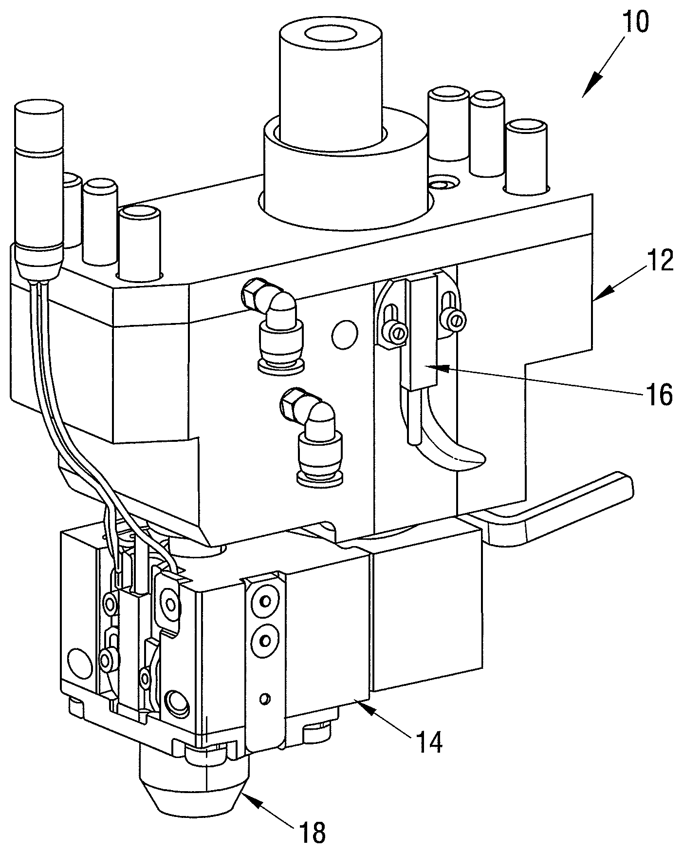
[0044] FIG. 1 shows a setting device 10 in a perspective view. It comprises a guide housing 12 and a guide plate 14. The setting device 10 has a sensor 16 by which it can be monitored whether the setting device 10 is in a closed state or in an open state. A base plate 18 is arranged at the guide plate 14 and can be brought into contact with a workpiece to fasten a fastening element to it.
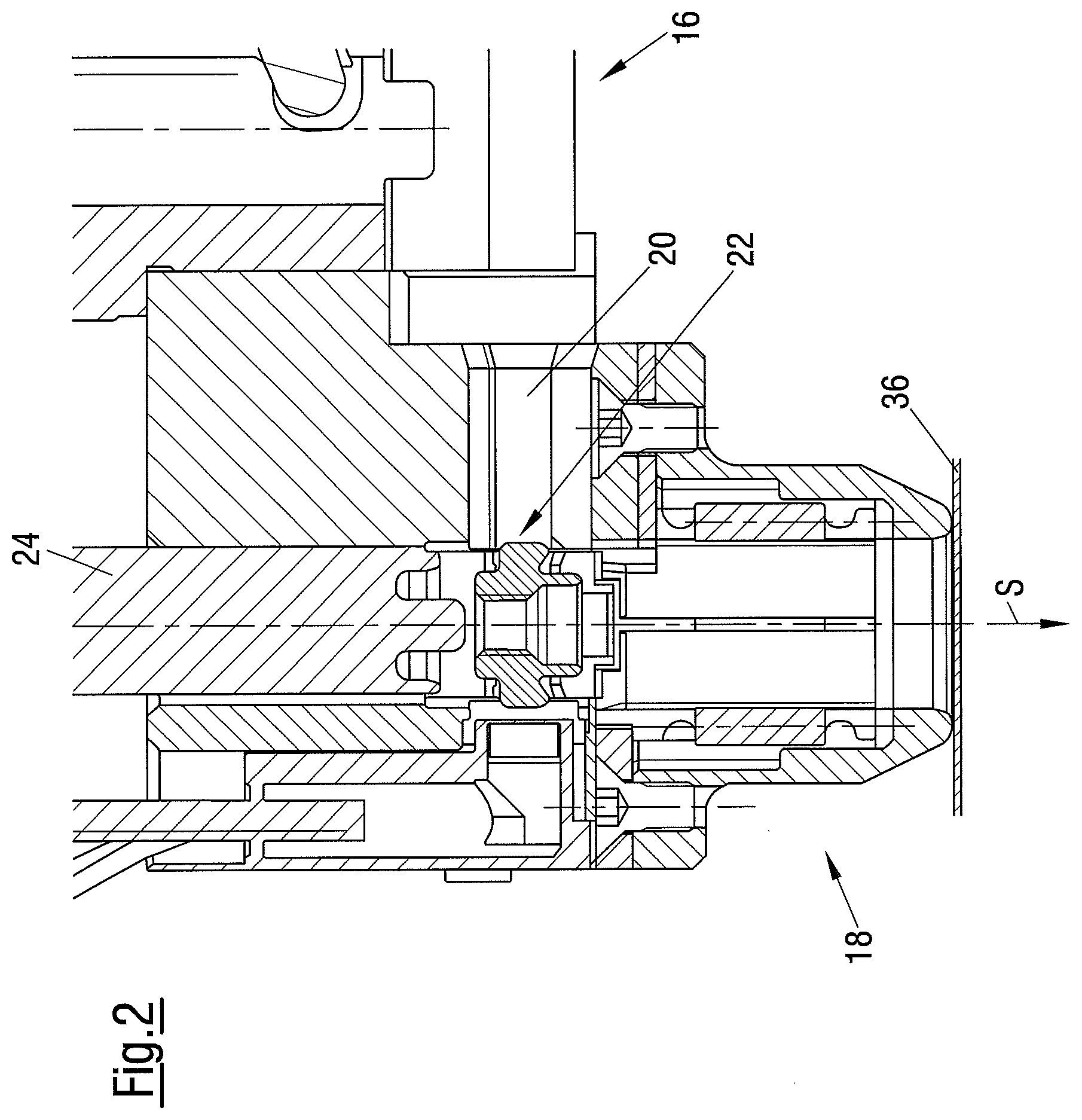
[0045] FIG. 2 shows a cross-section through a part of the guide plate 14 and through the base plate 18. The guide plate 14 has a supply passage 20 by which the fastening element 22 to be fastened to the workpiece can be brought into a position from where it can be pressed toward and into the workpiece by a ram or plunger 24 movable in a setting direction S. A starting situation/position is shown in FIG. 2 in which the element 22 is clamped by means of holding fingers. The setting device 10 is open and the element 22 can be processed. The base plate 18 has already been brought into contact with a surface of a workpiece 36 to which the element 22 should be fastened. It is understood that the workpiece 36 that is shown as a sheet metal part by way of example can also be differently configured. The same applies to the element 22.
[0046] In FIG. 3, starting from the starting situation, the element 22 is pressed by the ram 24 into a passage-like axial hollow space 26 of a guide device 28 of the base plate 18. The holding fingers are pressed back in this process.
[0047] The guide device 28 comprises a plurality of guide segments 30A, 30B. The segments 30A, 30B are separate components that are divided from one another by a slit 39, that each have a cross-section like a segment of a circle, and that are arranged such that they bound the hollow space 26 in the peripheral direction. They are preloaded by a preloading device not shown in detail in a direction toward a longitudinal axis 32H of the hollow space 26 that is arranged coaxially with a longitudinal axis 32S of the ram 24, that is radially inwardly. As soon as the element 22 enters into the hollow space 26, the segments 30A, 30B are urged outwardly against the preloading force generated by the preloading device.
[0048] FIG. 4 shows how the element 22 is pushed through the hollow space 26 of the guide device 28. In this respect, a peripheral surface 34 of the element 22 cooperates with the segments 30A, 30B. A reliable guidance of the element 22 is ensured by the preloading force since the risk of a tilting or canting of the element 22 is minimized.
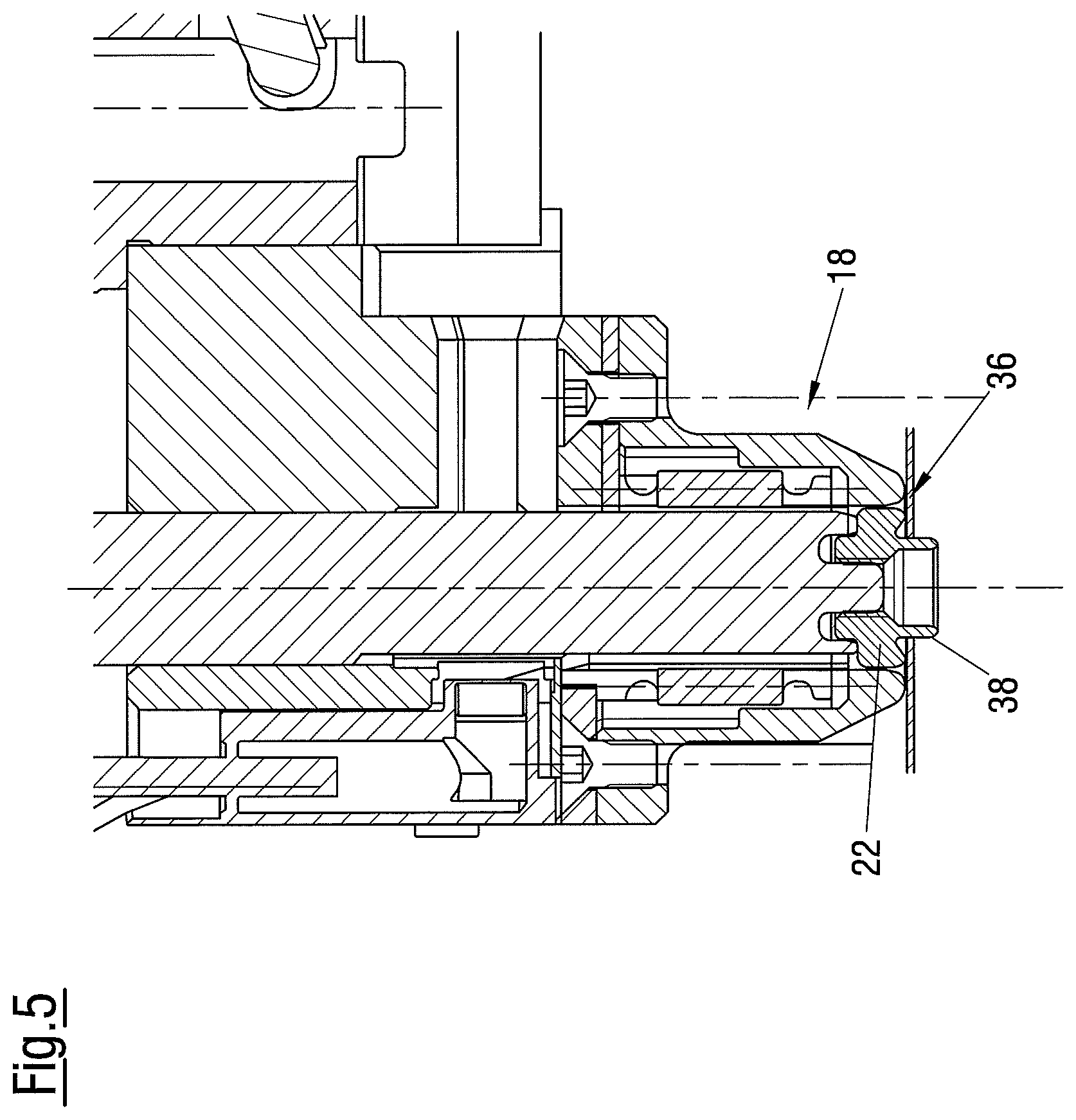
[0049] FIG. 5 shows how the element 22 is pressed into the only indicated workpiece 36. The element 22 is a self-piercing element. For reasons of simplicity, a shaping of a rivet section 38 of the element 22 is not shown that can be effected by the action of a die, not shown. For example, the shaped rivet section 38 engages behind the workpiece 38 at its rear side. A slug, not shown, has been removed. It is pointed out for reasons of completeness that the setting device 10 can generally also be used with non-self-piercing elements 22. The workpiece 36 is then prepunched in a suitable manner.
[0050] FIG. 6 shows the "normal case". After the fastening of the element 22 to the workpiece 36, the setting device 10 is removed from it and brought into a new setting position. This can be done by a movement of the setting device 10 or by a movement of the workpiece 36. Both the setting device 10 and the workpiece 36 can also be moved or a new workpiece 36 can be delivered. A new element 22 has already been brought into the starting position that has also already been shown in FIG. 2.
[0051] FIG. 7 shows a malfunction of the setting device 10. The first element 22 is still in the region of the guide device 28, for example because it has canted there, and blocks the hollow space provided to guide the element 22. The second element 22 already brought into the starting position would now be pressed against the first element 22 by the ram 24, which would very likely have the consequence of damage to the setting device 10, in particular to the guide device 28.
[0052] To recognize this malfunction, a detection device is provided by means of which the presence of an element 22 in the hollow space 26 can be detected. An embodiment of such a detection device is shown in FIG. 8. It is integrated in the guide device 28 whose components are shown in an exploded representation in FIG. 9.
[0053] The guide device 28 comprises four guide segments 30A, 30B, 30C, 30D (preferably composed of metal) that each form a peripheral section of the hollow space 26. They are separated from one another by insulating pins 40 that are arranged in slits 39 provided between adjacent guide segments 30A, 30B, 30C, 30C (see e.g. FIGS. 3, 10A, 10B). The insulating pins 40 can comprise an elastomer. They electrically insulate adjacent segments 30A, 30B, 30C, 30D and enable a relative movement of the segments 30A, 30B, 30C, 30D due to their elastic properties. Elastic rings 42A, 42B, 42C (e.g. 0 rings) are provided to generate the initially described preload of the segments 30A, 30B, 30C, 30D. They are disposed in correspondingly dimensioned grooves 44. The segments 30A, 30B, 30C, 30D are radially inwardly preloaded toward the elastic insulating pins 40 by the rings 42A, 42B, 42C. The rings 42A, 42B, 42C are stretched by an introduction of an element 22 into the hollow space 26. A force acting in a radial direction on the element 22 is ultimately thereby generated that stabilizes the location of the element 22.
[0054] As can be seen in FIG. 8, the electrically conductive segments 30A and 30B are connected to electrical conductors 46A, 46B. They permit a voltage to be applied between the elements 30A, 30B by means of a control device. If the element 22 is electrically conductive, it short circuits the segments 30A, 30B as soon as it enters into the hollow space 26 so that a current can flow, which is detected by the control device. It is generally also possible to determine the presence of the element 22 in an analog manner via a resistance measurement or via other electrical parameters.
[0055] Four segments 30A, 30B, 30C, 30D are provided in the embodiment shown in FIGS. 8 and 9 and two of them (30A and 30B) act as electrical contacts. It is understood that the number of guide segments provided and the kind of contacting (e.g. contact pairing) can be selected as required. It is furthermore possible not to use individual guide segments themselves as electrical contacts, but rather only to provide sections of one of the segments or a plurality of segments with electrical contacts.
[0056] An axial support of the guide device 28 or of the segments 30A, 30B, 30C, 30D in a housing 18A of the plate 18 takes place via an electrically insulating support ring 45.
[0057] A radial support can take place via the rings 42A, 42C since they project out of the grooves 44 in part and thus project over the segments 30A, 30B, 30C, 30D in the radial direction.
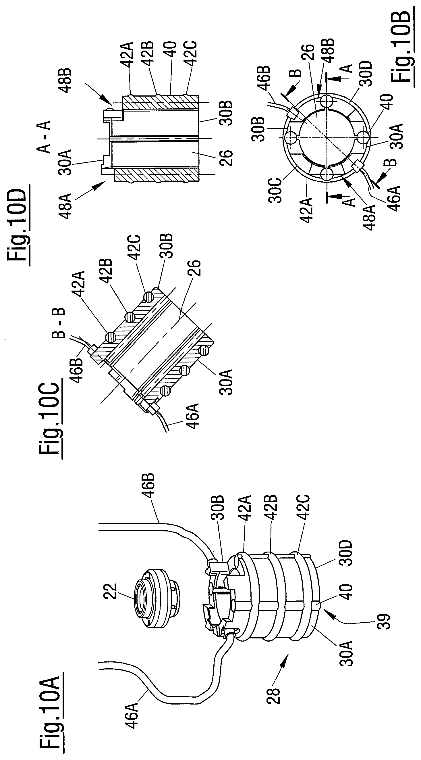
[0058] FIGS. 10A to 10D show a further embodiment of the guide device 28, wherein FIG. 10A is a perspective view and FIGS. 10B to 10D are transverse sections or longitudinal sections. The rings 42A, 42B, 42C and in the insulating pins 40 are formed in one piece. They can also only be connected to one another or can be separate components. In accordance with a particularly simple embodiment, the above-named components are molded to the segments 30A, 30B, 30C, 30D. Preferred materials from which said components can be formed are elastically deformable plastics, in particular elastomers. They are, for example, obtained by vulcanization of a thermoplastic natural rubber or of a synthetic rubber.
[0059] It can in particular be seen from FIGS. 10A and 10D that the segments 30A, 30B, 30C, 30D are provided at their respective upper sides with recesses 48A or 48B that enable an axial fixing of the segments 30A, 30B, 30C, 30D, which will be explained in more detail in the following.
[0060] FIG. 11 shows an alternative embodiment of the guide device 28. Insulating pins 40 are provided here that extend between the rings 42A, 42C in the axial direction, but do not project beyond them in the axial direction. The slits 39 are therefore only partly filled. Unlike what is shown, these components can be configured in one piece. The ring 42B disposed between the rings 42A, 42C in the axial direction has a substantially square basic shape and engages around the insulating pins 40 from the outside to generate an additional preload.
[0061] FIG. 12 shows the guide device 28 of FIG. 11 in a state assembled in the base plate 18. The conductors 46A, 46B are connected to a control device not shown in any more detail via a multipoint plug 50. An electrical connection to the guide plate 14 (see conductor 46C) is also established via the plug 50. The segments 30A, 30B, 30C, 30D are fixed in the housing 18A of the base plate 18 from above by a fixing element 52 and a supply rail 54. The supply rail 54 forms a part of the passage 20 (see FIG. 2).
[0062] FIG. 13 shows the base plate 18 in a sectional view. The axial fixing of the guide device 28 by the fixing element 52 and by the supply rail 54 can be recognized. The fixing element 52 is produced from insulating material and can therefore be in direct contact with the segment 30A. It is screwed to the housing 18A by means of a screw 56. The supply rail 54 that plays a role in the delivering of the element 22 into the starting position is, in contrast, insulated with respect to the segment 30B by means of an insulating plate 58. The fixing element 52 and the supply rail 54 engage into the recesses 48A and 48B respectively. The components 52, 54 can be composed of plastic.
[0063] FIGS. 14A to 14D show a further embodiment of the guide device 28, wherein FIG. 14A is a perspective view and FIGS. 14B to 14D are transverse sections or longitudinal sections. Instead of the insulating pins 40 of the embodiments in accordance with FIGS. 8, 9, and 10A to 10D having a substantially circular cross-section, insulating pins 40 having an approximately trapezoid cross-section are arranged in the slits 39 between adjacent segments 30A, 30B, 30C, 30D. The insulating pins 40 project in the radial direction outwardly beyond the segments 30A, 30B, 30C, 30D so that they enable a support of the guide device 28 in the housing 18A. In other words, the insulating pins 40 not only serve for the electrical insulation of the segments 30A, 30B, 30C, 30D with respect to one another, but also for their radial support. The elastic properties of the insulating pins 40 provide--with a suitable dimensioning of the radial overhang--the desired preload on the segments 30A, 30B, 30C, 30D. The radial inner sides of the insulating pins 40 are set back with respect to the inner sides of the segments 30A, 30B, 30C, 30D in order not to impede the movement of the element 22 through the hollow space 26. The insulating pins 40 can be separate components or can be molded to the segments 30A, 30B, 30C, 30D. They preferably comprise elastomer.
[0064] The concept of providing a preloading device by elements projecting outwardly in the radial direction and having elastic properties can generally also be implemented in isolation from the insulating pins 40. It is, for example--additionally or alternatively--possible to provide or mold elastic abutment sections that are supported in the housing 18A at the outer sides of the segments 30A, 30B, 30C, 30D. Conversely--additionally or alternatively--elastic contact sections that project radially inwardly can also be provided at the housing 18A and serve for the radial support of the guide device 28. The contact sections can be fastened to the guide device 28 and/or to the housing 18A or can molded thereto or can be separate components.
[0065] FIGS. 15A to 15D show a further embodiment of the guide device 28, wherein FIG. 15A is a perspective view and FIGS. 15B to 15D are transverse sections or longitudinal sections. Instead of the segments 30A, 30B, 30C, 30D, segments 30A, 30B, 30C, 30C', 300'', 30D, 30D', 30D'' are provided between which an insulating pin 40 is respectively arranged in a corresponding slit 39. This shows that in general any desired number of guide segments can be provided to take account of the respectively present demands in the best possible manner. The same applies to the number and to the configuration of the insulating pins. They can completely or also only partly fill the intervals between the guide segments and can generally have any desired configuration (e.g. cross-sectional geometry) according to requirements.
[0066] FIG. 16 shows an embodiment of the guide device 26 in which the segment 30B (as in the above-described embodiments) is directly connected to a conductor 46B. If an element 22 is introduced into the hollow space 26, it presses the segments 30A, 30B apart against the preload generated by the rings 42. A contact point 59A that is provided at the segment 30A thereby comes into contact with a contact point 59B that is provided at the housing 18A. The housing 18A is in turn connected to the conductor 46A. A circuit is thus also closed by the element 22 in this case, but with a minimal relative movement of the segments 30A, 30B fixed by a spacing of the contact points 59A, 59B in a base state having to be added to finally effect the closing of the circuit.
[0067] FIG. 17 shows a detection device in which the segment 30A has a plurality of detector elements 60--for example contact surfaces--that are each connected to one another pairwise. If the element 22 is in a position in which the two contact surfaces 60 of a connected pair are in contact with it, a circuit is again closed, which enables a determination of the position of the element 22 in the hollow space 26. This situation is illustrated in FIG. 17 by way of example with reference to the location of the element 22 by which the two topmost detector elements 60 are short circuited.
[0068] Instead of the contact points 60, other sensors and/or signal sources can also be provided that also do not necessarily have to be functionally coupled to one another pairwise. Sound sources and sound sensors can, for example, be provided that detect a reflection of sound waves at the element 22. The detector elements 60 can also be movement sensors or vibration sensors to detect changes of the oscillation/vibration pattern or of the eigen vibration of the guide device 28 or of the base plate 18 (the elements 60--or at least one element 60--can then also be attached to the housing 18A inwardly or outwardly) that is caused by the presence/location/position of an element 22 in the hollow space. The detector elements 60 can also be optical or magnetic sensors or pressure sensors or sensors of a different type (e.g. embedded measurement coils).
[0069] FIG. 18 shows a further embodiment of the guide device 28. Detector elements 60 are here provided both at the segment 30A and at the segment 30B. They can, for example, be coupled to one another such that oppositely disposed detector elements 60 form a pair that serves for the generation of a signal (e.g. a contact surface pair or a transmitter/receiver pair). It is, however, also possible to control and/or to monitor the individual elements 60 individually or in groups to obtain a more exact image of the position of the element 22 and/or of its location in space. A tilted element 22 was drawn by way of example in FIG. 18 that contacts two detector elements/contact surfaces 60 that are not disposed opposite one another due to the location of said element 22 and thus closes a circuit between these elements 60, which is recognized by the control device and is interpreted as a malfunction.
[0070] FIG. 19 shows a plan view of a guide segment 30A having a plurality of detector elements 60 that are not only arranged distributed in an axial direction (cf. setting direction S), but also in a peripheral direction.
[0071] It becomes clear from FIGS. 17 to 19 that a number, arrangement, and functional grouping of detector elements 60 can be selected absolutely as required (in particular with respect to the desired spatial resolution of the element detection). The type of detector elements used (inter alia electrical measurement--e.g. voltage, current, resistance--measurement of acoustic signals, measurement of vibrations and/or movements and/or of spacings, measurement of optical signals, measurement of mechanical parameters--e.g. pressure and/or strain) is also generally freely selectable. Different detector types can also be combined to provide a detection device suitable for the respective application.
[0072] FIG. 20 shows an embodiment of a detection device that is based on the measurement of a spacing change between the segments 30A, 30B. For this purpose, a connection element 61 is provided that serves as a measurement device, that bridges the slit 39, and that connects the two segments 30A, 30B to one another. It can, for example, be an electrical conductor whose electrical properties are influenced by a length change or it can be a strain gauge.
[0073] It is also possible to additionally or alternatively detect and evaluate a change of the spacing between the segments 30A, 30B and the housing 18A. For this purpose, for example, distance sensors 62 (e.g. capacitive sensors) are provided that are shown in FIG. 21. Additionally or alternatively to the distance sensors 62, strain gauges or piezo receivers can also be provided.
[0074] FIG. 22 shows a detection device that is based on the measurement of a pressure in the region of the guide device 28. Compressed air is introduced into the hollow space 26 for this purpose (see arrow D). The pressure adopted is measured at one or more points in the housing 18A, in particular in or adjacent to the hollow space 26, by means of corresponding pressure sensors 64. The pressure adopted at the one measurement point or at the plurality of measurement points inter alia depends on whether and where applicable where an element 22 is located in the hollow space 26.
REFERENCE NUMERAL LIST
[0075] 10 setting device
[0076] 12 guide housing
[0077] 14 guide plate
[0078] 16 sensor
[0079] 18 base plate
[0080] 20 supply channel
[0081] 22 fastening element
[0082] 24 plunger or ram
[0083] 26 hollow space
[0084] 28 guide device
[0085] 30A, 30B, 30C,
[0086] 30C', 300'', 30D,
[0087] 30D', 30D'' guide segment
[0088] 32H, 32S longitudinal axis
[0089] 34 peripheral surface
[0090] 36 workpiece
[0091] 38 rivet section
[0092] 39 slit
[0093] 40 insulating pin
[0094] 42, 42A, 42B, 42C ring
[0095] 44 groove
[0096] 45 support ring
[0097] 46A, 46B conductor
[0098] 48A, 48B recess
[0099] 50 plug
[0100] 52 fixing element
[0101] 54 supply rail
[0102] 56 screw
[0103] 58 insulating plate
[0104] 59A, 59B contact point
[0105] 60 detector element
[0106] 61 connection element
[0107] 62 distance sensor
[0108] 64 pressure sensor
[0109] S setting direction
[0110] D compressed air
* * * * *
D00000
D00001
D00002
D00003
D00004
D00005
D00006
D00007
D00008
D00009
D00010
D00011
D00012

D00013

D00014

D00015

D00016

XML
uspto.report is an independent third-party trademark research tool that is not affiliated, endorsed, or sponsored by the United States Patent and Trademark Office (USPTO) or any other governmental organization. The information provided by uspto.report is based on publicly available data at the time of writing and is intended for informational purposes only.
While we strive to provide accurate and up-to-date information, we do not guarantee the accuracy, completeness, reliability, or suitability of the information displayed on this site. The use of this site is at your own risk. Any reliance you place on such information is therefore strictly at your own risk.
All official trademark data, including owner information, should be verified by visiting the official USPTO website at www.uspto.gov. This site is not intended to replace professional legal advice and should not be used as a substitute for consulting with a legal professional who is knowledgeable about trademark law.