Golf Club Head
TSUNASHIMA; Hiromasa ; et al.
U.S. patent application number 16/426652 was filed with the patent office on 2019-12-12 for golf club head. This patent application is currently assigned to Sumitomo Rubber Industries, Ltd.. The applicant listed for this patent is Sumitomo Rubber Industries, Ltd.. Invention is credited to Masahide ONUKI, Hiromasa TSUNASHIMA.
| Application Number | 20190374823 16/426652 |
| Document ID | / |
| Family ID | 68764510 |
| Filed Date | 2019-12-12 |


View All Diagrams
| United States Patent Application | 20190374823 |
| Kind Code | A1 |
| TSUNASHIMA; Hiromasa ; et al. | December 12, 2019 |
GOLF CLUB HEAD
Abstract
A hollow golf club head comprises a face portion having a club face for hitting a ball, and a main body portion including a crown wall, a side wall and a sole wall which extend from the face portion toward the rear of the head. At least one of the walls of the main body portion is provided with a folded portion for facilitating a partial elastic deformation of the main body portion when the face portion hits a ball. The folded portion includes a first folded portion and a second folded portion each extending in the front-back direction of the head while swinging in the thickness direction of the wall. The first folded portion and the second folded portion are continuous with each other and extend along the peripheral edge of the club face, and have different phases in the swing.
| Inventors: | TSUNASHIMA; Hiromasa; (Kobe-shi, JP) ; ONUKI; Masahide; (Kobe-shi, JP) | ||||||||||
| Applicant: |
|
||||||||||
|---|---|---|---|---|---|---|---|---|---|---|---|
| Assignee: | Sumitomo Rubber Industries,
Ltd. Hyogo JP |
||||||||||
| Family ID: | 68764510 | ||||||||||
| Appl. No.: | 16/426652 | ||||||||||
| Filed: | May 30, 2019 |
| Current U.S. Class: | 1/1 |
| Current CPC Class: | A63B 53/0408 20200801; A63B 53/0466 20130101; A63B 53/0437 20200801; A63B 53/0433 20200801; A63B 53/04 20130101; A63B 53/0445 20200801 |
| International Class: | A63B 53/04 20060101 A63B053/04 |
Foreign Application Data
| Date | Code | Application Number |
|---|---|---|
| Jun 6, 2018 | JP | 2018-108288 |
Claims
1. A hollow golf club head comprising: a face portion having a face for striking a ball; and a main body portion including a crown wall, a side wall and a sole wall which walls extend from the face portion toward the rear of the head, wherein at least one wall of the crown wall, the side wall and the sole wall is provided with a folded portion for facilitating a partial elastic deformation of the main body portion when the face portion hits a ball, the folded portion includes a first folded portion and a second folded portion, each of the first folded portion and the second folded portion extends in a font-back direction of the head while swinging in the thickness direction of the wall, the first folded portion and the second folded portion are continuous with each other along the peripheral edge of the face portion, and the phase of the swing of the first folded portion is different from the phase of the swing of the second folded portion.
2. The golf club head according to claim 1, wherein the difference in the phase of the swing between the first folded portion and the second folded portion is a half cycle.
3. The golf club head according to claim 1, wherein the folded portion is formed so as to extend across at least two adjacent walls of the crown wall, the side wall and the sole wall, and a junction at which the first folded portion is connected to the second folded portion is formed at a position corresponding to that of the boundary between the two adjacent walls.
4. The golf club head according to claim 3, wherein the junction extends in a zigzag shape in the front-back direction of the head.
5. The golf club head according to claim 1, wherein each of the first folded portion and the second folded portion has a valley recessed toward a center of the head and a mountain protruding toward the outer side of the head, both with respect to a reference line of the swing.
6. The golf club head according to claim 5, wherein the first folded portion comprises the mountain and the two valleys located on both sides of the mountain in the front-back direction of the head, and two first triangular elements whose length in a first direction which is the direction along the peripheral edge of the face is gradually increased from the mountain toward the respective valleys.
7. The golf club head according to claim 6, wherein the second folded portion comprises the valley and the two mountains located on both sides of the valley in the front-back direction of the head, and two second triangular elements whose length in the above-said first direction is gradually decreased from the valley toward the respective mountains.
8. The golf club head according to claim 7, wherein the second triangular element and the first triangular element is continuous with each other by sharing one side with each other.
9. The golf club head according to claim 7, wherein the first folded portion and the second folded portion are repeatedly and alternately arranged in the first direction.
10. The golf club head according to claim 1, wherein the folded portion is formed so as to extend over the crown wall, the side wall and the sole wall.
11. The golf club head according to claim 7, wherein each of the first triangular element and the second triangular element is defined by straight sides.
12. The golf club head according to claim 1, wherein the folded portion has a structure including a diamond cut surface.
13. The golf club head according to claim 2, wherein each of the first folded portion and the second folded portion has at least one valley recessed toward a center of the head and at least one mountain protruding toward the outer side of the head, both with respect to a reference line of the swing, wherein the first folded portion comprises one mountain and two valleys located on both sides of the mountain in the front-back direction of the head, and two first triangular elements whose length in a first direction which is the direction along the peripheral edge of the face is gradually increased from the mountain toward the respective valleys, wherein the second folded portion comprises one valley and two mountains located on both sides of the valley in the front-back direction of the head, and two second triangular elements whose length in the above-said first direction is gradually decreased from the valley toward the respective mountains.
14. The golf club head according to claim 13, wherein the second triangular element and the first triangular element is continuous with each other by sharing one side with each other.
15. The golf club head according to claim 13, wherein the folded portion is formed so as to extend over the crown wall, the side wall and the sole wall.
16. The golf club head according to claim 3, wherein each of the first folded portion and the second folded portion has at least one valley recessed toward a center of the head and at least one mountain protruding toward the outer side of the head, both with respect to a reference line of the swing, wherein the first folded portion comprises one mountain and two valleys located on both sides of the mountain in the front-back direction of the head, and two first triangular elements whose length in a first direction which is the direction along the peripheral edge of the face is gradually increased from the mountain toward the respective valleys, wherein the second folded portion comprises one valley and two mountains located on both sides of the valley in the front-back direction of the head, and two second triangular elements whose length in the above-said first direction is gradually decreased from the valley toward the respective mountains.
17. The golf club head according to claim 16, wherein the second triangular element and the first triangular element is continuous with each other by sharing one side with each other.
18. The golf club head according to claim 16, wherein the folded portion is formed so as to extend over the crown wall, the side wall and the sole wall.
19. A hollow golf club head comprising: a face portion having a face for hitting a ball, and a main body portion including a crown wall, a side wall and a sole wall which walls extend from the face portion toward the rear of the head, wherein at least one of the crown wall, the side wall and the sole wall is provided with a folded portion for facilitating a partial deformation of the main body portion when the face portion hits a ball, and the folded portion comprises a diamond cut face.
Description
TECHNICAL FIELD
[0001] The present invention relates to a golf club head, more particularly to a hollow golf club head.
BACKGROUND ART
[0002] Heretofore, various attempts have been made to improve the rebound performance of a golf club head in order to increase the flight distance of a hit ball.
[0003] For example, Patent Document 1 below describes that a sole portion of a golf club head is provided with a folded portion extending in the toe-heel direction in substantially parallel to the leading edge of the head. [0004] Patent Document 1: Japanese Patent Application Publication No. 2016-182356
SUMMARY OF THE INVENTION
Problems to be Solved by the Invention
[0005] The present inventors found out that it is possible to significantly improve the rebound performance of a golf club head by forming a novel folded structure in at least a part of the main body portion of the head comprising a crown wall, a side wall and a sole wall which walls extend from the face portion of the head toward the rear of the head.
[0006] It is therefore, an object of the present invention to provide a golf club head which can help to increase the flight distance of a hit ball.
[0007] According to one aspect of the present invention, a hollow golf club head comprises:
[0008] a face portion having a face for striking a ball; and
[0009] a main body portion including a crown wall, a side wall and a sole wall which walls extend from the face portion toward the rear of the head, wherein
[0010] at least one wall of the crown wall, the side wall and the sole wall is provided with a folded portion for facilitating a partial elastic deformation of the main body portion when the face portion hits a ball,
[0011] the folded portion includes a first folded portion and a second folded portion,
[0012] each of the first folded portion and the second folded portion extends in a font-back direction of the head while swinging in the thickness direction of the wall,
[0013] the first folded portion and the second folded portion are continuous with each other and extends along the peripheral edge of the face portion, and
[0014] the phase of the swing of the first folded portion is different from the phase of the swing of the second folded portion.
[0015] In the golf club head according to the present invention, the folded portion is formed such that the first folded portions and the second folded portions having different phases are continuous along the peripheral edge of the face portion. Such folded portion effectively reduces the rigidity of the wall in the ball hitting direction. Therefore, the main body portion exhibits a large amount of elastic deformation at the time of hitting the ball, and the golf club head according to the present invention can exhibit high rebound performance. Thus, the golf club head of the present invention can increases the flight distance of the hit ball.
[0016] The difference in the phase of the swing between the first folded portion and the second folded portion may be a half cycle.
[0017] The folded portion may be formed so as to extend across at least two adjacent walls of the crown wall, the side wall and the sole wall. In this case, the junction at which the first folded portion is connected to the second folded portion may be formed at a position corresponding to that of the boundary between the two adjacent walls.
[0018] The junction may extend in a zigzag shape in the front-back direction of the head.
[0019] Each of the first folded portion and the second folded portion may have a valley recessed toward the inside of the head and a mountain protruding toward the outside of the head, both with respect to a reference line of the swing.
[0020] The first folded portion may comprise: the one mountain and the two valleys located on both sides of the mountain in the front-back direction of the head, and two first triangular elements whose length in a first direction which is the direction along the peripheral edge of the face is gradually increased from the mountain toward the respective valleys.
[0021] The second folded portion may comprise: The one valley and the two mountains located on both sides of the valley in the front-back direction of the head, and two second triangular elements whose length in the above-said first direction is gradually decreased from the valley toward the respective mountains.
[0022] The second triangular element and the first triangular element may be continuous with each other by sharing one side with each other.
[0023] The first folded portion and the second folded portion may be repeatedly and alternately arranged in the first direction.
[0024] Each of the first triangular element and the second triangular element may be defined by straight sides.
[0025] The folded portion may have a structure including a diamond cut surface.
[0026] The folded portion may be formed so as to extend over the crown wall, the side wall and the sole wall.
[0027] According to another aspect of the present invention, a hollow golf club head comprise:
[0028] a face portion having a face for hitting a ball, and
[0029] a main body portion including a crown wall, a side wall and a sole wall which walls extend from the face portion toward the rear of the head, wherein
[0030] at least one of the crown wall, the side wall and the sole wall is provided with a folded portion for facilitating a partial deformation of the main body portion when the face portion hits a ball, and
[0031] the folded portion comprises a diamond cut face.
[0032] Therefore, the golf club heads according to the present invention can increase the flight distance of a hit ball.
BRIEF DESCRIPTION OF THE DRAWINGS
[0033] FIG. 1 is a front view of a golf club head as a first embodiment of the present invention.
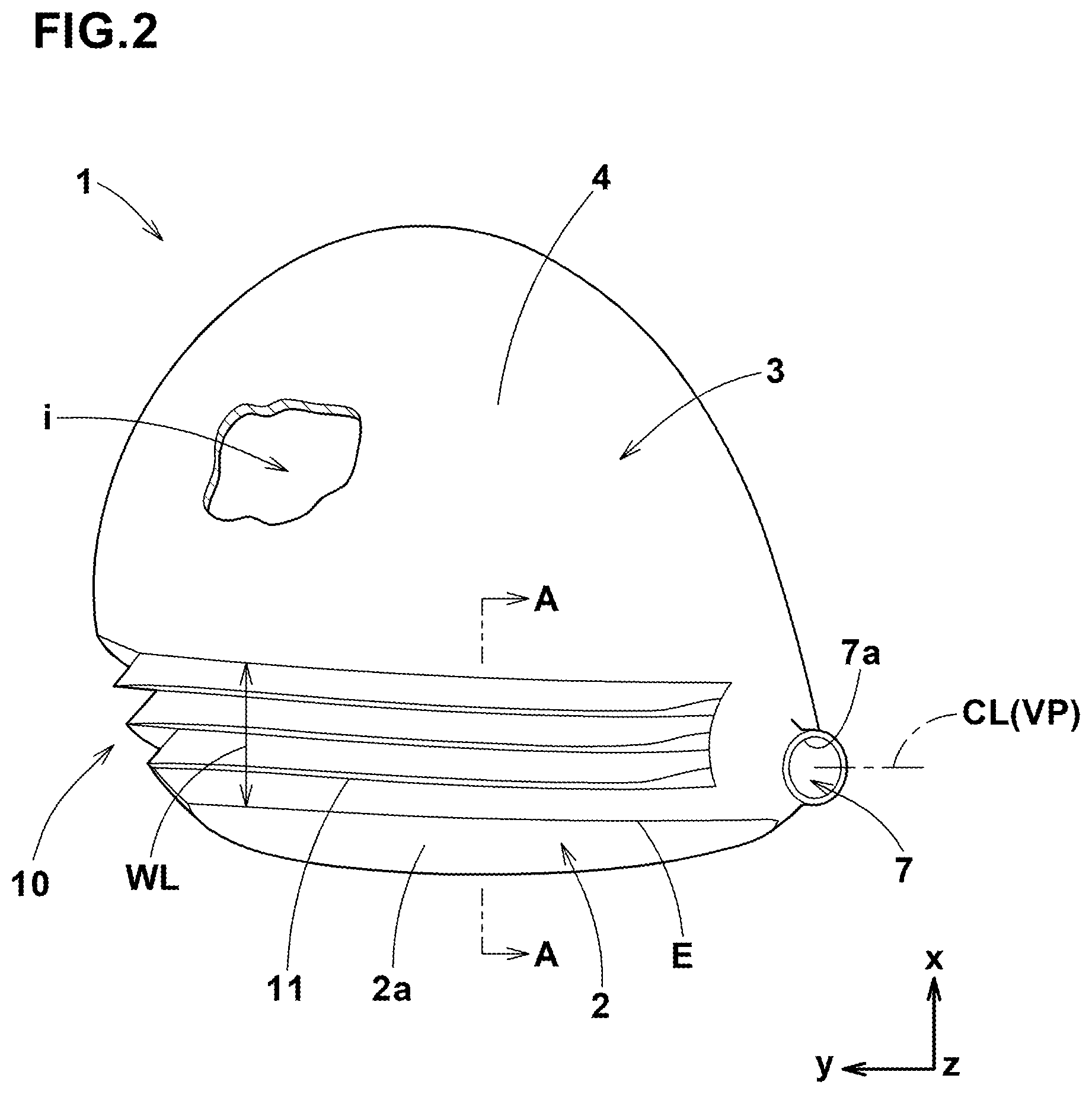
[0034] FIG. 2 is a top view of the golf club head shown in FIG. 1.
[0035] FIG. 3 is a side view of the golf club head shown in FIG. 1 as viewed from the toe side.
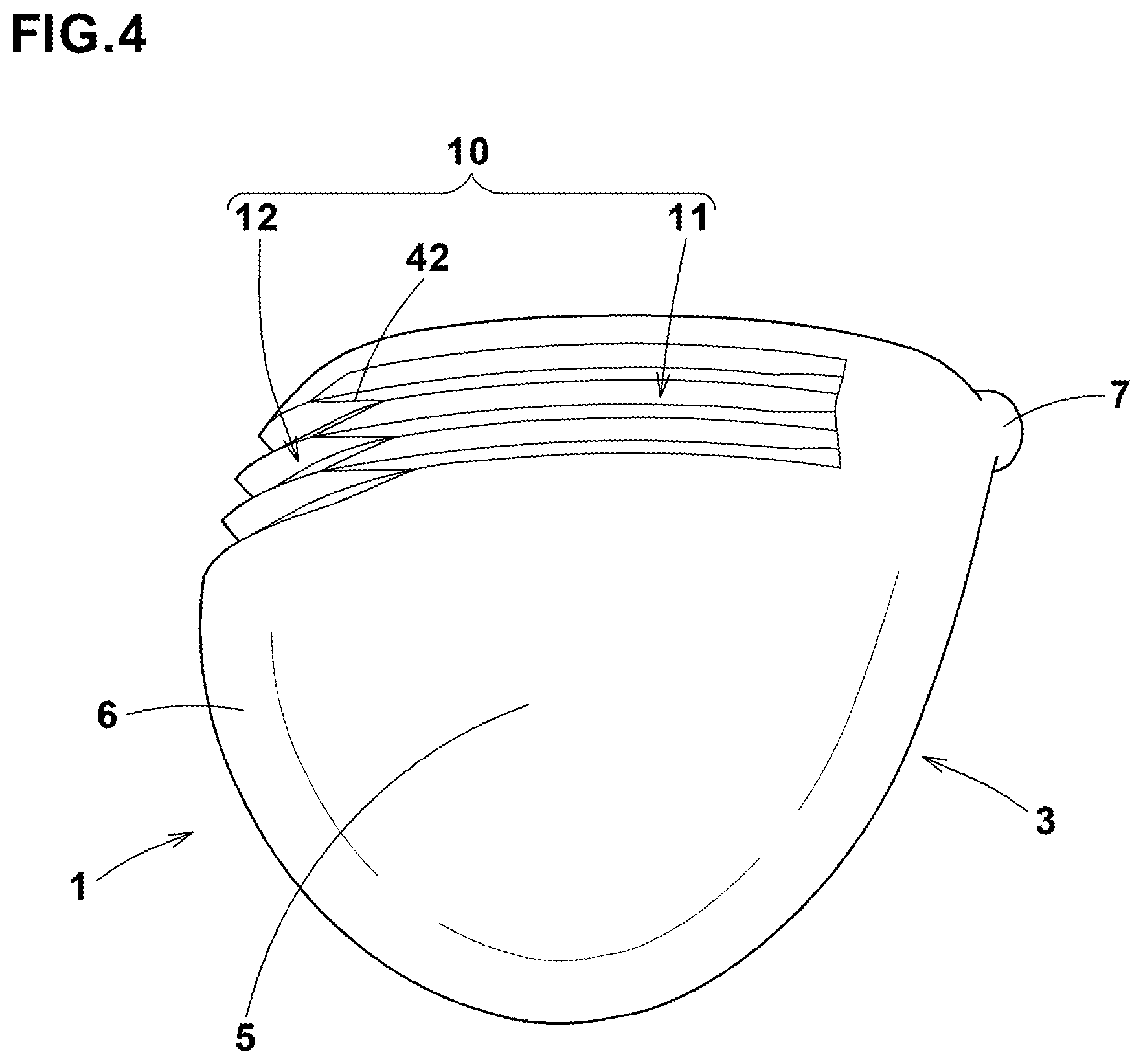
[0036] FIG. 4 is a bottom view of the golf club head shown in FIG. 1.
[0037] FIG. 5 is a perspective view of the golf club head shown in FIG. 1.
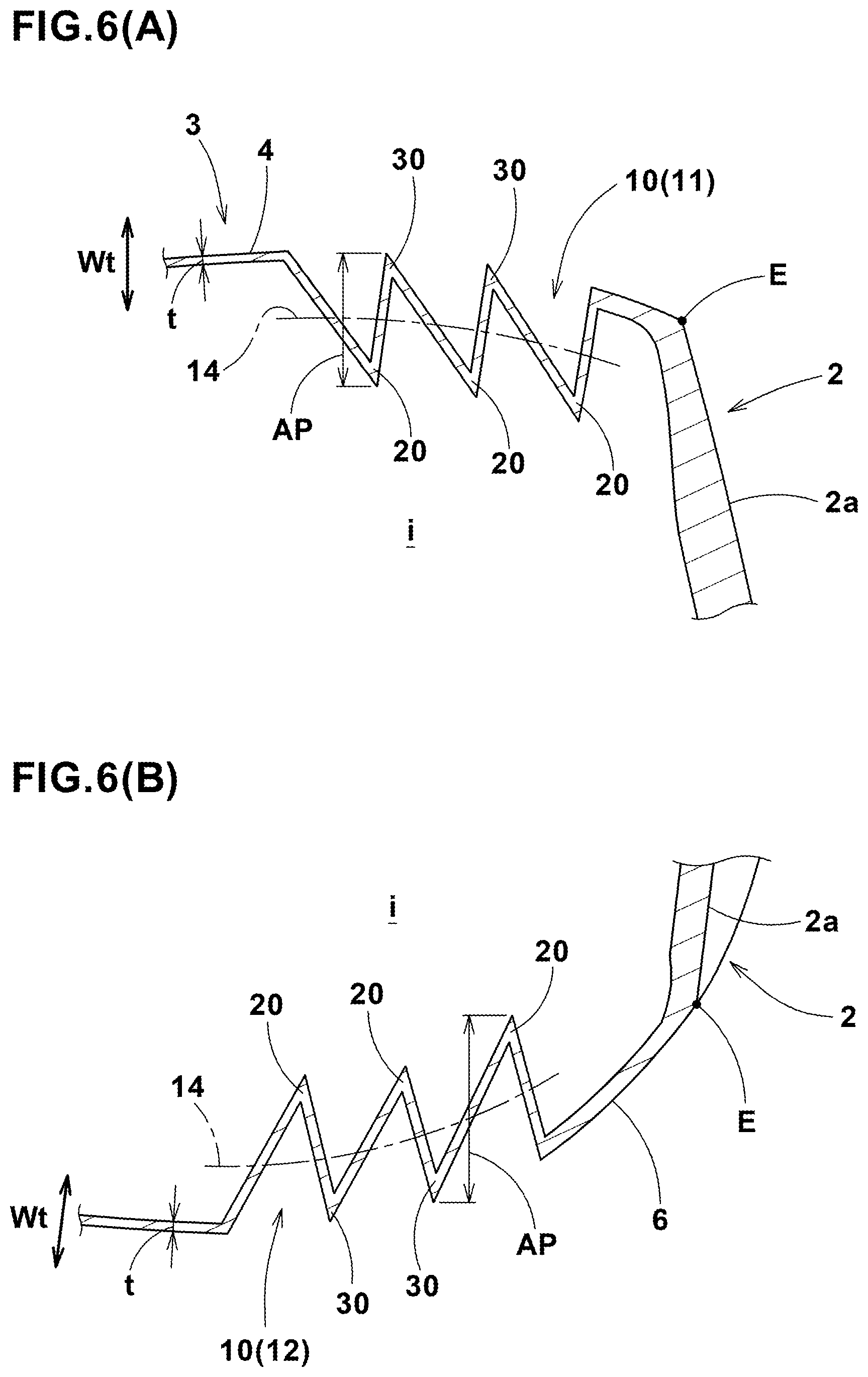
[0038] FIG. 6(A) is a cross-sectional view taken along line A-A of FIG. 2.
[0039] FIG. 6(B) is a cross-sectional view taken along line B-B of FIG. 3.
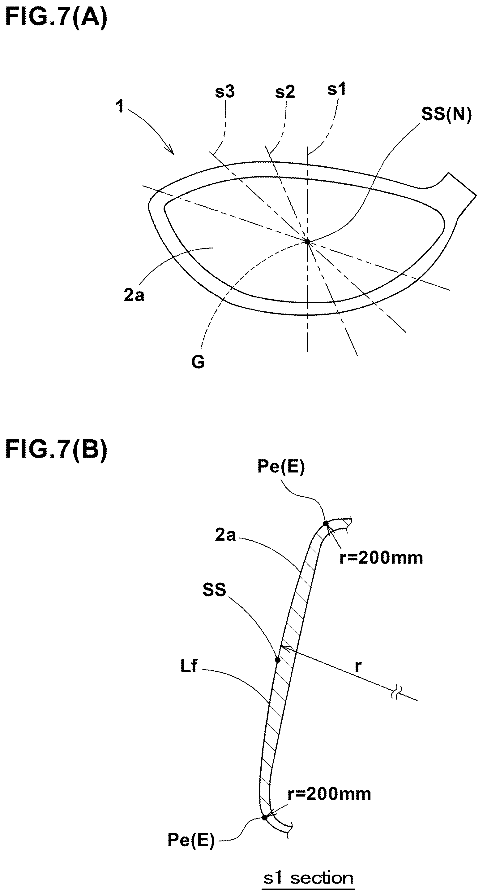
[0040] FIG. 7(A) and FIG. 7(B) are a front view of a golf club head and a cross-sectional view taken along s1 of FIG. 7(A) for explaining the peripheral edge of a club face.
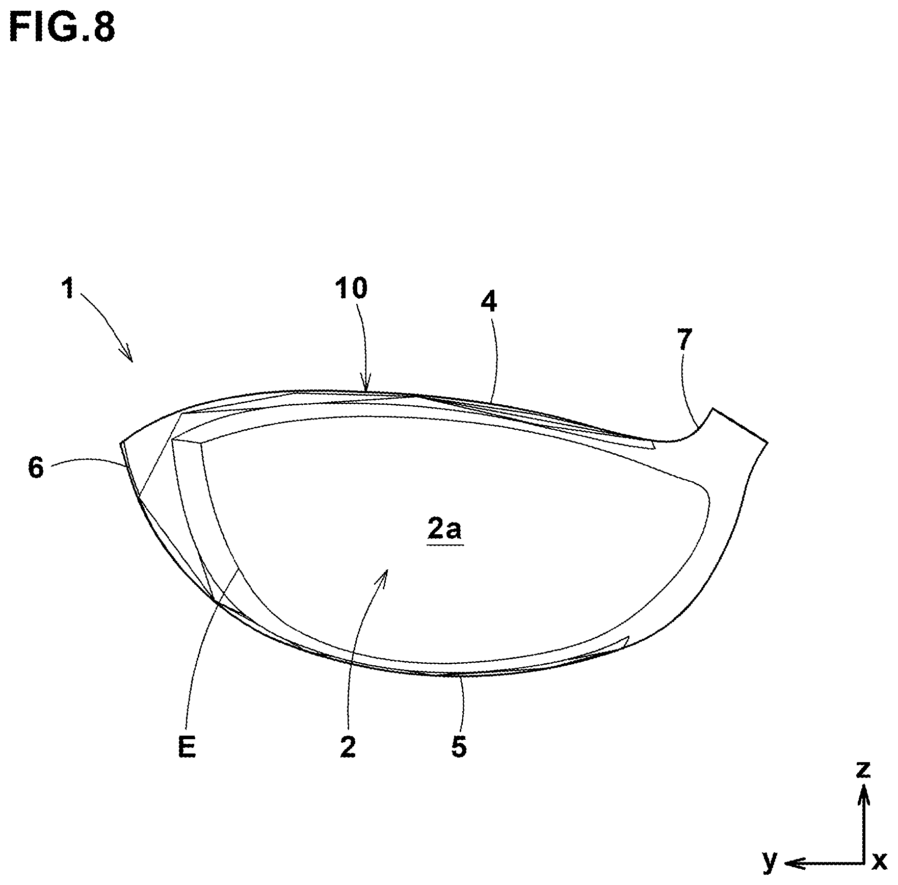
[0041] FIG. 8 is a front view of a golf club head a second embodiment of the according to the present invention.
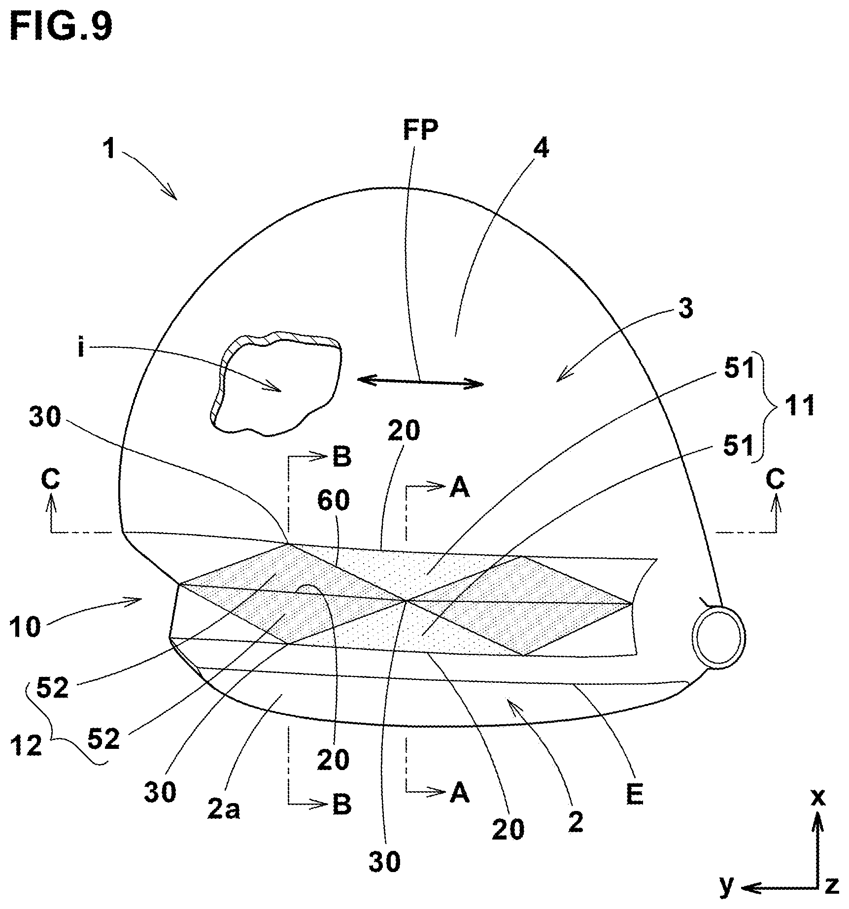
[0042] FIG. 9 is a plan view of the golf club head shown in FIG.
[0043] 8.
[0044] FIG. 10 is a side view of the golf club head shown in FIG. 8 as viewed from the toe side.
[0045] FIG. 11 is a bottom view of the golf club head shown in FIG. 8.
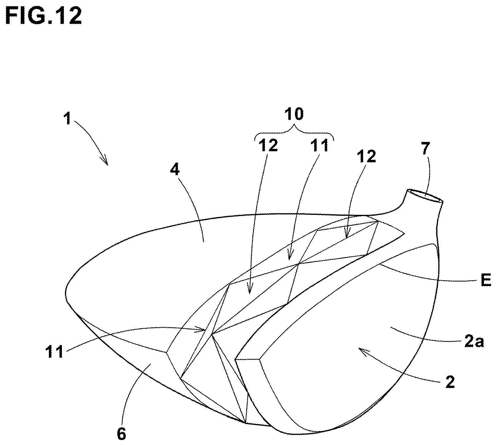
[0046] FIG. 12 is a perspective view of the golf club head shown in FIG. 8.
[0047] FIG. 13(A) is a cross-sectional view taken along line A-A of FIG. 9.
[0048] FIG. 13(B) is a cross-sectional view taken along line B-B of FIG. 9.
[0049] FIG. 14 is a perspective view of a golf club head as a further embodiment of the present invention.
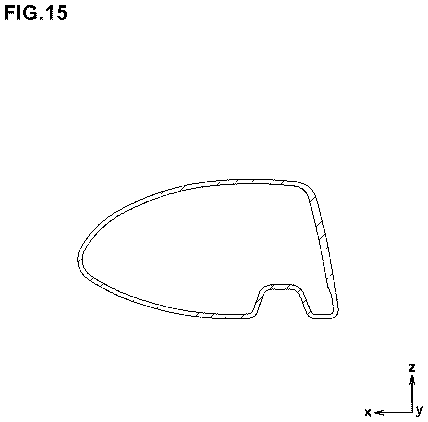
[0050] FIG. 15 is a cross-sectional view of a golf club head as a comparative example 2.
DESCRIPTION OF THE PREFERRED EMBODIMENTS
[0051] Embodiments of the present invention will now be described in conjunction with accompanying drawings.
[0052] The embodiments described in detail below and the specific configurations shown in the drawings are only for understanding the present invention. The present invention is not limited to the specific configurations illustrated. Further, in the following description, it is to be noted that the same or common elements are denoted with the same reference numerals, and redundant description is omitted.
[0053] FIGS. 1 to 5 show a golf club head 1 as a first embodiment of the present invention (hereinafter simply referred to as the "head") under its reference state.
[Reference State of Head ]
[0054] The reference state of the head 1 is such a state in which the head 1 is set on a horizontal plane HP at its loft angle a (FIG. 3) and lie angle p (FIG. 1) with respect to the horizontal plane HP, while locating a club shaft center line CL of the head 1 within a vertical plane VP. [0055] The toe-heel direction of the head 1 means a horizontal direction y parallel with the vertical plane VP. [0056] The front-back direction of the head means a horizontal direction x orthogonal to the vertical plane VP. [0057] The up-down direction of the head means a vertical direction z orthogonal to both of the directions x and y.
[Basic Configuration of Head ]
[0058] In the embodiment shown in FIGS. 1 to 5, the head 1 is provided therein with a hollow i (shown in FIG. 2), and the head 1 is formed as a typical wood type club head. And the head 1 in this example is for a driver.
[0059] Here, the wood-type club heads include at least driver (#1), a brassie (#2), a spoon (#3), a buffy (#4) and a creek (#5). In addition, the wood-type heads include a head having a shape similar to those listed above even if the number or designation/name are different from those listed above.
[0060] Further, the head 1 may be configured as a utility type or an iron type club head.
[0061] The head 1 of this embodiment is made of, for example, a metal material. As the metal material, various metal materials, e.g. titanium, titanium alloys, stainless steels, aluminum alloys and the like can be used.
[0062] Further, the head 1 may be partially made of a nonmetallic material, e.g. resin, rubber, elastomer, fiber reinforced resin and the like.
[0063] The head 1 in this embodiment is composed of a face portion 2 and a main body portion 3 extending from the face portion 2 toward the rear of the head.
[0064] The front surface of the face portion 2 defines a club face 2a for striking a ball. The face portion 2 is formed in a plate shape. The back surface (not shown) of the face portion 2 faces the hollow i.
[0065] The main body portion 3 comprises a crown wall 4, a sole wall 5 and a side wall 6 which are formed to surround the hollow
[0066] The crown wall 4 extends from the face portion 2 so as to form the upper surface of the head. The sole wall 5 extends from the face portion 2 so as to form the bottom surface of the head. The side wall 6 extends between the crown wall 4 and the sole wall 5 and forms the side surface of the head. [0067] A toe side and a heel side of the side wall 6 are connected to a toe side and a heel side of the face portion 2, respectively.
[0068] The hollow i is located behind the face portion 2, and enclosed by the face portion 2, the crown wall 4, the sole wall 5 and the side wall 6.
[0069] For example, in a heel side of the crown wall 4, a hosel portion 7 may be formed as shown in FIGS. 1 and 2. For example, the hosel portion 7 is formed in a tubular shape having a shaft insertion hole 7a into which a club shaft (not shown) is attached. The center line of the shaft insertion hole 7a corresponds to the center line CL of the club shaft attached to the head.
[Folded Portion of First Embodiment ]
[0070] In the head 1 in this embodiment, at least one of the crown wall 4, the sole wall 5 and the side wall 6 of the main body portion 3 is provided with a folded portion 10 as shown in FIGS. 1 and 2. The folded portion 10 functions to facilitate a partial elastic deformation of the main body portion 3 when the face portion 2 hits a ball.
[0071] Preferably, the folded portion 10 is formed so as to extend between at least two adjacent walls selected from the crown wall 4, the side wall 6 and the sole wall 5.
[0072] In this embodiment, the folded portion 10 extends from the crown wall 4 to the sole wall 5 through a toe side part of the side wall 6. Such folded portion 10 extending over the three walls 4, 5 and 6 like this is particularly preferred. But, it is also possible that the folded portion 10 is formed within only one of the crown wall 4, the side wall 6 and the sole wall 5.
[0073] The folded portion 10 includes a first folded portion 11 and a second folded portion 12.
[Configurations of First and Second Folded Portions ]
[0074] FIGS. 6(A) and 6(B) are cross-sectional views of the first folded portion 11 and the second folded portion 12 taken along line A-A of FIG. 2 and line B-B of FIG. 3, respectively,
[0075] As shown, each of the first folded portion 11 and the second folded portion 12 has a folded structure extending in the front-back direction of the head while swinging in the thickness direction of the wall, namely, moving from the outside to the inside of the head.
[0076] Here, the "thickness direction of the wall" means, as shown by the symbol "wt" in FIGS. 6(A) and 6(B), the direction of the thickness of the wall (here, the crown wall 4 or side wall 6) in which the first folded portion 11 or second folded portion 12 is formed.
[Swing]
[0077] The "swing" means that, in the cross section as shown in FIGS. 6(A) and 6(B), the wall swings between one side and the other side in the thickness direction wt of a reference line 14 during the wall extends from the front side to the rear side.
[0078] The folded structure of this embodiment comprises a valley 20 recessed toward the inside of the head from the reference line 14, and a mountain 30 projecting toward the outside of the head from the reference line 14, and the valley 20 and the mountain 30 are arranged repeatedly and alternately in the front-back direction of the head.
[0079] As far as the mountain 30 projects toward the outside of the head from the reference line 14 of the swing, the mountain 30 may project or may not project toward the outside of the head from the surface of a portion other than the folded structure of the main body portion 3 (for example, the smooth surface of the crown wall).
[0080] As far as the valley 20 is recessed toward the inside of the head from the reference line 14 of the swing, the valley 20 may be recessed or may not be recessed toward the inside of the head from the surface of a portion other than the folded structure of the main body portion 3 (for example, the smooth surface of the crown wall).
[0081] In any way, in the folded portion 10, the wall is folded in a zigzag manner and extends in the front-back direction of the head.
[0082] In the figures (cross sections), the valleys 20 and the mountains 30 intersect at acute angles to have a zigzag line (that is, ridge lines and valley lines appear in the outer surface of the head). [0083] However, the folded structure may be configured to have a curved line such as a wavy line, a sine curve and the like. In this case, no clear line may not appear in the outer surface of the head.
[0084] In the folded structure in this embodiment, the first folded portion 11 and the second folded portion 12 are continuous with each other, and extend along the peripheral edge E of the club face 2a. [0085] Further, the phase of the swing of the first folded portion 11 is different from the phase of the swing of the second folded portion 12. [0086] The folded portion 10 having such structure can effectively reduce the rigidity in the ball hitting direction. Therefore, when the face portion hits a ball, the main body portion 3 exhibits a large amount of partial elastic deformation, and the head 1 exhibits high rebound performance. As a result, the head 1 can increase the flight distance of the hit ball.
[0087] Further advantage of the folded portion 10 in this embodiment is that deformation when hitting a ball is less likely to be concentrated at a specific position in the longitudinal direction of the folded portion 10 (in the direction along the peripheral edge E of the club face 2a). Therefore, for example, even when a ball hits off the center of the club face 2a, the folded portion 10 can elastically deform in the ball hitting direction (the front-back direction) almost equally in the longitudinal direction. As a result, the direction of the club face 2a at the time of off-center hit is stabilized, and the directivity of the hit ball is improved.
[Peripheral Edge ]
[0088] In this invention, when the club face 2a is defined by a clear ridge line, the peripheral edge E of the club face 2a means the ridge line. However, when there is no clear ridge line, the peripheral edge E is determined as follows: in each cross section s1, s2, s3 . . . as shown in FIG. 7(A) which includes a normal line N to the club face 2a drawn from the gravity center G of the head to the sweet spot ss, a position Pe at which the radius r of curvature of the outer surface Lf of the club face 2a becomes 200 mm for the first time in the course from the sweet spot ss toward the outside of the club face 2a as shown in FIG. 7(B) is obtained, and an envelope curve passing the positions Pe obtained from the cross sections s1, s2, s3 . . . is determined. Then, the peripheral edge E of the club face 2a is defined by the envelope curve. [0089] Incidentally, the sweet spot ss is a point of intersection of the club face 2a and the normal line N.
[0090] Hereafter, the direction FP along the peripheral edge E as shown in FIG. 5 is referred to as the "1st direction". Here, the expression "along the peripheral edge E" does not require to be completely parallel with the peripheral edge E.
[0091] It is preferable that the difference in the above-said phase between the first folded portion 11 and the second folded portion 12 is a half cycle. More specifically, the first folded portion 11 and the second folded portion 12 are preferably arranged such that each mountain 30 of the first folded portion 11 is continuous with one of the valleys 20 of the second folded portion 12, and each valley 20 of the first folded portion 11 is continuous with one of the mountains 30 of the second folded portion 12.
[0092] It is preferable that the junction 40 at which the first folded portion 11 is connected to the second folded portion 12 is formed at a position corresponding to the boundary between the two walls of the main body portion 3.
[0093] In the folded portion 10 in this embodiment, the first folded portion 11 is formed in the crown wall 4 and the second folded portion 12 is formed in the side wall 6, and the junction 40 therebetween is formed along the border between the crown wall 4 and the side wall 6. [0094] In this embodiment, a further first folded portion 11 is formed in the sole wall 5, and a junction 42 at which the further first folded portion 11 and the above-said second folded portion 12 are connected to each other is formed along the border between the sole wall 5 and the side wall 6.
[0095] The junctions 40 and 42 are each configured by a mountain fold which extends in the front-back direction of the head in a zigzag shape while connecting the respective mountains 30 between the first folded portion 11 and the second folded portion 12. The mountain fold is a portion which is bent so as to protrude outward of the head. [0096] Such junctions 40 and 42 can smoothly connect between the first folded portion 11 and the second folded portion 12 which are formed in the different walls having the different phases.
[0097] At the time of off-center shot, for example, where the ball hits a toe side of the club face 2a, the elastic deformation in the front-back direction of the head occurring more directly in the second folded portion 12 in the side wall 6 can be transmitted smoothly through the junctions 40 and 42 to the first folded portion 11 in the crown wall 4 and/or the first folded portion 11 in the sole wall 5. This facilitates elastic deformation of the first folded portions 11 in the crown wall 4 and the sole wall 5. Therefore, the junctions 40 and 42 in this embodiment can cause elastic deformation which is more uniform in the longitudinal direction of the folded portion 10 even if the club face 2a makes off-center shot, and the directionality of the hit ball can be improved.
[0098] The thickness t of each of the crown wall 4, the sole wall 5 and the side wall 6 (inclusive of the folded portion 10) can be variously set according to the conventional practice, and is not to be particularly limited. [0099] For example, preferably, the thickness t of each of the walls 4 to 6 may be set in a range from 0.5 to 3.5 mm.
[0100] As shown in FIG. 2, the width WL in the front-back direction of the head of the folded portion 10 is not to be particularly limited. But, in order to provide a sufficient deformation area in the main body portion 3, it is preferred that the width WL is 10 mm or more, more preferably 20 mm or more.
[0101] The folded structure of each of the first folded portion 11 and the second folded portion 12 includes at least one cycle made up of one valley 20 and one mountain 30. [0102] In order that the main body portion 3 is provided with a sufficient deformation area, it is preferable for each folded structure to include 1.5 cycles or more, more preferably 2 cycles or more.
[0103] In the folded structure of the first folded portion 11 and the folded structure of the second folded portion 12, the peak-to-peak amplitude AP of the swing from the valley 20 to the mountain 30 in the cross section as shown in FIGS. 6(A) and 6(B), is not to be particularly limited. But, in order to provide a sufficient deformation area for the main body portion 3, it is preferred that the amplitude AP is set to be not less than 1.5 times, more preferably not less than 2.0 times the thickness t of the wall provided with the folded portion concerned.
[Folded Portion of Second Embodiment ]
[0104] Next, a golf club head 1 as a second embodiment of the present invention will be described in conjunction with FIGS. 8 to 13. The difference of the head 1 of the second embodiment from the first embodiment is only the configuration of the folded portion 10.
[0105] FIGS. 13(A) and 13(B) are cross-sectional views taken along line A-A and line B-B of FIG. 9 which show the first folded portion 11 and the second folded portion 12, respectively.
[0106] As shown, in the second embodiment too, each of the first folded portion 11 and the second folded portion 12 comprises a valley 20 recessed toward the inside of the head from the reference line 14 of the swing, and a mountain 30 projecting toward the outside of the head from the reference line 14.
[0107] As shown in FIG. 13(A), the first folded portion 11 comprises one mountain 30 and two valleys 20 positioned on both sides of the mountain in the front-back direction x of the head 1. Further, as shown in FIG. 9, the first folded portion 11 comprises two first triangular elements 51, wherein the length in the first direction FP of each first triangular element 51 is gradually increased from the mountain 30 to the valley 20. In this embodiment, the two first triangular elements 51 constituting the first folded portion 11 are substantially isosceles triangles of substantially the same shape, and the apexes thereof are connected to each other as shown in FIG. 9.
[0108] As shown in FIG. 13(B), the second folded portion 12 comprises one valley 20 and two mountains 30 located on both sides of the valley in the front-back direction x of the head. Further, as shown in FIG. 9, the second folded portion 12 comprises two second triangular elements 52, wherein the length in the first direction FP of each second triangular element 52 is gradually decreased from the valley 20 to the mountain 30. In this embodiment, the two second triangular elements 52 constituting the second folded portion 12 are substantially isosceles triangles of substantially the same shape, and the bases thereof are connected to each other. In other words, one side is shared with each other.
[0109] Preferably, the first triangular element 51 and the second triangular element 52 are each defined by straight sides 60.
[0110] Preferably, the first triangular element 51 and the second triangular element 52 are each formed as being flat in the outer surface of the head.
[0111] Such configuration helps to make the folded portion 10 more flexible when hit a ball.
[0112] The second triangular element 52 and the first triangular element 51 are connected to each other by sharing the sides 60 with each other. Those sides 60 constitute a junction 44 between the first folded portion 11 and the second folded portion 12 which portions are different from each other in the phase of the swig by a half cycle.
[0113] Such a folded portion 10 of the second embodiment is called as a diamond cut surface.
[0114] In this embodiment, the first folded portion 11 and the second folded portion 12 are arranged repeatedly and alternately in the first direction FP.
[0115] In this example, as shown in FIG. 9, the crown wall 4 includes the first folded portion 11 and the second folded portion 12. Further, as shown in FIG. 10 and FIG. 11, each of the side wall 6 and the sole wall 5 includes the first folded portion 11 and the second folded portion 12. [0116] Thus, in this example of the second embodiment, each of the three walls 4 to 6 of the main body portion 3 includes both of the first folded portion 11 and the second folded portion 12.
[0117] As another example of the second embodiment, only one of the crown wall 4, the side wall 6 and the sole wall 5 may be provided with the diamond cut surface. FIG. 14 shows such example. In this example, more mountains 30 and valleys 20 can be formed in the front-back direction of the head.
[0118] While detailed description has been made of preferable embodiments of the present invention, the present invention can be embodied in various forms without being limited to the illustrated embodiments.
[0119] It is to be noted that, in this description, it is intended that an element and its variants described in an embodiment are applicable to a corresponding element of another embodiment, even if not explicitly stated.
Comparison Test
[0120] In order to confirm the effects of the present invention, a plurality of hollow titanium alloy golf club heads were designed, and then using their FEM models, the rebound performance of each head was obtained through a computer simulation.
[0121] All of the heads had the same specifications except for the folded portions. The specifications of each head are as follows.
[0122] Comparative Example 1 is a golf club head not provided with a folded portion.
[0123] Comparative Example 2 is a golf club head provided in the sole wall with a groove extending in the toe-heel direction as shown in FIG. 15.
[0124] Example 1 is a golf club head provided with the folded portion shown in FIGS. 1-6.
[0125] Example 2 is a golf club head provided with the folded portion (diamond cut surface type) shown in FIGS. 8-13.
[0126] The rebound performance of each head was evaluated by the coefficient of restitution (COR) of the head. [0127] In reference to the test procedure of the U.S.G.A., the velocities of a ball before and after collision were calculated by colliding the ball with the center of the club face at a predetermined velocity, and then the velocity ratio was obtained as the coefficient of restitution (OCR). [0128] The results are indicated in Table 1 by an index base on Comparative Example 2 being 100, wherein the larger the value, the better the rebound performance.
TABLE-US-00001 [0128] TABLE 1 Comparative Comparative Head Example 1 Example 2 Example 1 Example 2 OCR 98 100 104 102
[0129] From the test results, it was confirmed that, as compared with the coefficient of restitution of comparative Example 1, [0130] although the improvement of comparative Example 2 was only 2.0%, Example 1 was improved by 6.1% and Example 2 was improved by 4.1%.
DESCRIPTION OF THE REFERENCE SIGNS
[0131] 1 golf club head
[0132] 2 face portion
[0133] 2a club face
[0134] 3 main body portion
[0135] 4 crown wall
[0136] 5 sole wall
[0137] 6 side wall
[0138] 10 folded portion
[0139] 11 first folded portion
[0140] 12 second folded portion
[0141] 14 reference line
[0142] 20 valley
[0143] 30 mountain
[0144] 40 junction
[0145] 42 junction
[0146] 44 junction
[0147] 51 first triangular element
[0148] 52 second triangular element
[0149] 60 one side
[0150] E peripheral edge
[0151] FP first direction
[0152] i hollow claims
* * * * *
D00000
D00001
D00002
D00003
D00004
D00005
D00006
D00007
D00008
D00009
D00010
D00011
D00012
D00013

D00014

D00015
XML
uspto.report is an independent third-party trademark research tool that is not affiliated, endorsed, or sponsored by the United States Patent and Trademark Office (USPTO) or any other governmental organization. The information provided by uspto.report is based on publicly available data at the time of writing and is intended for informational purposes only.
While we strive to provide accurate and up-to-date information, we do not guarantee the accuracy, completeness, reliability, or suitability of the information displayed on this site. The use of this site is at your own risk. Any reliance you place on such information is therefore strictly at your own risk.
All official trademark data, including owner information, should be verified by visiting the official USPTO website at www.uspto.gov. This site is not intended to replace professional legal advice and should not be used as a substitute for consulting with a legal professional who is knowledgeable about trademark law.