Endoscopic Needle Carrier
HERNANDEZ; Juan ; et al.
U.S. patent application number 16/331833 was filed with the patent office on 2019-12-12 for endoscopic needle carrier. This patent application is currently assigned to IRCAD, INSTITUT DE RECHERCHE CONTRE LES CANCERS DE L'APPAREIL DIGESTIF. The applicant listed for this patent is INSTITUT HOSPITALO-UNIVERSITAIRE DE CHIRURGIE MINI-INVASIVE GUIDEE PAR L'IMAGE, IRCAD, INSTITUT DE RECHERCHE CONTRE LES CANCERS DE L'APPAREIL DIGESTIF. Invention is credited to Juan HERNANDEZ, Andras LEGNER.
| Application Number | 20190374217 16/331833 |
| Document ID | / |
| Family ID | 57190175 |
| Filed Date | 2019-12-12 |


View All Diagrams
| United States Patent Application | 20190374217 |
| Kind Code | A1 |
| HERNANDEZ; Juan ; et al. | December 12, 2019 |
ENDOSCOPIC NEEDLE CARRIER
Abstract
An endoscopic needle holder for handling curved needles includes an articulated assembly including a first gripping jaw forming one piece with a duct and a second gripping jaw actuated by the movable core in transverse displacement; the jaws are made of coaxial cylindrical parts with the mobile core; the first jaw has a plurality of longitudinally extending peripheral teeth; the second jaw consists of a cylindrical part with a plurality of peripheral teeth; and the second jaw is movable with respect to the first jaw by a longitudinal linear displacement between a rest position, where the jaws are spaced to delimit, between the ends of the teeth, an interval at least equal to the section of a needle and a close position where they keep the needle curved.
| Inventors: | HERNANDEZ; Juan; (Strasbourg Cedex, FR) ; LEGNER; Andras; (Strasbourg Cedex, FR) | ||||||||||
| Applicant: |
|
||||||||||
|---|---|---|---|---|---|---|---|---|---|---|---|
| Assignee: | IRCAD, INSTITUT DE RECHERCHE CONTRE
LES CANCERS DE L'APPAREIL DIGESTIF Strasbourg FR INSTITUT HOSPITALO-UNIVERSITAIRE DE CHIRURGIE MINI-INVASIVE GUIDEE PAR L'IMAGE Strasbourg FR |
||||||||||
| Family ID: | 57190175 | ||||||||||
| Appl. No.: | 16/331833 | ||||||||||
| Filed: | September 1, 2017 | ||||||||||
| PCT Filed: | September 1, 2017 | ||||||||||
| PCT NO: | PCT/FR2017/052318 | ||||||||||
| 371 Date: | March 8, 2019 |
| Current U.S. Class: | 1/1 |
| Current CPC Class: | A61B 2017/00398 20130101; A61B 2017/2926 20130101; A61B 17/062 20130101; A61B 17/0469 20130101; A61B 2017/00862 20130101 |
| International Class: | A61B 17/04 20060101 A61B017/04; A61B 17/062 20060101 A61B017/062 |
Foreign Application Data
| Date | Code | Application Number |
|---|---|---|
| Sep 9, 2016 | FR | 16/58445 |
Claims
1. An endoscopic needle holder for handling a curved needle comprising: a remote actuator at one end of the needle holder; at another end, an articulated assembly comprising a first gripping jaw forming one piece with a duct and a second gripping jaw actuated by a mobile core in transverse displacement; the jaws including coaxial cylindrical parts with the mobile core; the first jaw including a plurality of longitudinally extending peripheral teeth; the second jaw including cylindrical parts with a plurality of peripheral teeth; and the second jaw being movable with respect to the first jaw by a longitudinal linear displacement between a rest position, where the jaws are spaced to delimit, between the ends of the teeth, an interval at least equal to a section of the needle and a close position where they keep the needle curved.
2. The endoscopic needle holder according to claim 1 wherein the peripheral teeth of the second jaw are offset angularly with respect to the teeth of the first jaw.
3. The endoscopic needle holder according to claim 1 wherein the jaws have an alternation of peripheral teeth and peripheral grooves of complementary shapes and positions to the teeth of the opposite jaw.
4. The endoscopic needle holder according to claim 1 wherein the teeth have a polygonal cross section in the transverse plane.
5. The endoscopic needle holder according to claim 1 wherein each of the jaws has three teeth and three grooves for receiving the teeth of the complementary jaw.
6. The endoscopic needle holder according to claim 1 wherein an outer surface of the teeth is semi-cylindrical.
7. The endoscopic needle holder according to claim 1 wherein an enveloping surface of the teeth has a section identical to the section of the jaws.
8. The endoscopic needle holder according to claim 1 wherein an enveloping surface of the teeth has a section which is smaller than the section of the jaws.
9. The endoscopic needle holder according to claim 1 wherein an enveloping surface of the teeth has a section which is greater than the section of the jaws.
10. The endoscopic needle holder according to claim 1 wherein the second jaw has a hemispherical end.
11. The endoscopic needle holder according to claim 1 wherein a section of the teeth, in a radial plane, is rectangular.
12. The endoscopic needle holder according to claim 1 wherein a section of the teeth, in a radial plane, has an inclined inner edge.
13. The endoscopic needle holder according to claim 1 wherein a section of the teeth, in a radial plane, has a crenellated inner edge with a decreasing width between an end of the tooth and a base of the tooth.
14. The endoscopic needle holder according to claim 1 wherein a section of the teeth, in a radial plane, has an enlarged upper end.
15. The endoscopic needle holder according to claim 1 wherein at least a portion of the teeth is elastically deformable, and has a flared end.
16. The endoscopic needle holder according to claim 1 wherein the teeth are formed by cutting a tubular casing of the jaws.
17. The endoscopic needle holder according to claim 1 wherein the first jaw has a central channel of polygonal section which is complementary to a cross section of the movable core.
18. The endoscopic needle holder according to claim 1 wherein at least some of the teeth are axially movable.
19. The endoscopic needle holder according to claim 1 wherein an end of the teeth has an oblique face in the tangential plane of the jaws.
20. The endoscopic needle holder according to claim 19 wherein characterized in that each of the jaws has teeth with complementary oblique faces, and the second jaw is free to rotate with respect to the first jaw and comprises an elastic means with a torque aimed at bringing together oblique faces of the complementary teeth.
21. The endoscopic needle holder according to claim 1 further comprising an end adapted to be connected to a motorized system.
Description
CROSS-REFERENCE TO RELATED APPLICATIONS
[0001] This application is a National Phase Entry of International Patent Application No. PCT/FR2017/052318, filed on Sep. 1, 2017, which claims priority to French Patent Application No. 16/58445, filed on Sep. 9, 2016, both of which are incorporated by reference herein.
TECHNICAL FIELD
[0002] This invention relates to the field of needle holders for grasping and suturing in minimally invasive endoscopic surgery or laparoscopy. Such needle holders are usually consists of a forceps with two articulated jaws and placed at the end of a shaft. One of the jaws is in a fixed position, the other is actuated by the handle of the endoscope with a gripping surface of the needle.
[0003] In laparoscopy, the forceps is used alone; in flexible endoscopy, it is introduced through a flexible endoscope. The invention more particularly relates to a needle holder for endoscopic manipulation of curved suture needles, applied to flexible endoscopy, laparoscopy and robotic versions. Handling such needles has difficulties even for an experienced surgeon because the curved needles tend to rotate inside the pair of jaws that hold the needle.
BACKGROUND
[0004] For example, we know of U.S. Pat. No. 5,257,999 that describes a laparoscopic needle holder made up of a stem and a set of jaws controlled at one end by an opening and closing mechanism. The gripping surfaces of the jaws are in-curved to adapt to a curved surgical needle. One jaw has a convex shape while the other jaw has a corresponding concave shave. The shape of the gripping surfaces of the incurved jaws automatically directs the curved surgical needle to a desired suture position. The shape of the set of jaws also makes it easy to release and grip the curved surgical needle again during the suturing process of a laparoscopic operation.
[0005] Also known is U.S. Pat. No. 8,480,689 describing a suture device for gripping a flexible needle to adopt an incurved rest state.
[0006] Also known is a solution described in U.S. Patent Publication No. 2011/190794 concerning a medical needle holder consisting of a handle disposed at the proximal end and a needle receiver disposed at the distal tip. The needle receiver has a first and a second gripping surface that face gripping surfaces each other and extend in a transverse direction to the longitudinal axis of the carrier. The gripping surfaces are movable relative to each other via the handle, in the direction of the longitudinal axis of the support.
[0007] U.S. Patent Publication No. 2011/270281 discloses another example of a needle holder having an elongated body portion with a proximal end and a distal tip. A rotating head is configured to be disposed at the distal end of the body portion and an actuating member configured to be arranged at the proximal end of the body portion. The actuator is in functional cooperation with a handle assembly to allow rotational movement of the rotating head. The rotating head further cooperates with a moving needle in relation to the rotating head.
[0008] With the solutions of the prior art, the surgeon has to angularly direct the jaws, generally articulated relative to a transverse pivot, in order to fit the needle between the two jaws, and then close these jaws on the needle. The initial step of directing the jaws, angularly and in depth, can be very delicate and sometimes requires several tens of minutes of trial and error, especially when the needle to be grasped is in an area of low endoscopic visibility or is inconveniently positioned. With the solutions of the prior art, the gripping of the needle is done with a precise radial direction, corresponding to the symmetry plane of the jaws and the orientation in this plane from the centre line to the open space between the two jaws. Even when the surgeon is able to position the jaws angularly and longitudinally with respect to the needle, he still has to control the radial movement to position the needle at the right level between the jaws. These procedures are particularly delicate in endoscopic surgery, where the needle is just hard to see and where the surgeon has little information on the progress of his trial and error. The solution proposed by U.S. Patent Publication Nos. 2011/90794 or 2011/270281 is also unsatisfactory because it allows only a very poor maintenance of the needle, which tends to disengage as soon as it exerts an effort to make it penetrate into tissue.
SUMMARY
[0009] In order to remedy these drawbacks, the invention, in its most general sense, relates to an endoscopic needle holder for handling curved needles comprising a remote actuating mechanism provided at one of the ends of the needle holder, and at the other end an articulated assembly comprising a first gripping jaw forming one piece with a duct and a second movable gripping jaw actuated by the mobile core in transverse displacement, characterized in that: [0010] said jaws are made up of coaxial cylindrical parts with said mobile core; [0011] said first jaw has a plurality of peripheral teeth extending longitudinally; [0012] said second jaw is made up of a cylindrical part that has a plurality of peripheral teeth angularly offset in relation to the teeth of the first jaw; [0013] said second jaw is mobile with respect to the first jaw by a longitudinal linear movement between a rest position, where the jaws are spaced to delimit, between the ends of the teeth, an interval at least equal to the section of a needle and a close position where they keep the needle curved.
[0014] The first jaw is fixed in transverse displacement but may nevertheless have a degree of freedom in rotation about the longitudinal axis with respect to the tube. It is constrained in transverse displacement with respect to the tube and constrained in rotation with respect to the second jaw (by means of a polygonal stem for example).
[0015] According to the embodiment, the teeth are fixed with respect to the jaw, or elastically retractable. According to a variant, said first jaw has a transverse frontal surface provided with a plurality of peripheral teeth extending perpendicularly to said front surface: [0016] said second jaw consists of a cylindrical piece having a transverse surface provided with a plurality of peripheral teeth; [0017] said jaws are movable by longitudinal linear movement between a rest position, where the jaws are spaced to delimit, between the ends of the teeth, an interval at least equal to the section of a needle and a close position where they keep the needle curved.
[0018] With the solution proposed by the invention, the gripping end has a circular geometry that no longer requires a particular radial orientation with respect to the position of the needle. Whatever the position of the needle in the transverse plane passing between the two jaws, it can be hooked by one or more teeth, and the approximation of the jaws can then grasp and hold it firmly. According to one variant, the teeth of the second jaw are angularly offset with respect to the teeth of the first jaw.
[0019] Preferably, said jaws have an alternation of peripheral teeth and peripheral grooves of shapes and positions that are complementary to the teeth of the opposite jaw. According to an advantageous variant, said teeth in the transverse plane have a polygonal cross section. According to a particular embodiment, each jaw has three teeth and three grooves for receiving the teeth of the complementary jaw. According to an advantageous variant, the outer surface of the teeth is semi-cylindrical.
[0020] According to different variants: [0021] The enveloping surface of said teeth has a section that is identical to the section of said jaws. The outer surface thus extends the periphery of the corresponding jaw to have a peripheral surface devoid of asperities. [0022] The enveloping surface of said teeth has a section which is smaller than the section of said jaws. In this case, the teeth are recessed from the perimeter of the corresponding jaw, which prevents the ends of the teeth from damaging the tissues in contact with the end of the endoscope. [0023] The enveloping surface of said teeth has a section which is greater than the section of said jaws. In this case, the teeth protrude from the periphery of the corresponding jaw. This enables the attachment of the curved needle when it is close to the jaws.
[0024] According to a variant, said second jaw has a hemispherical end. It thus facilitates the introduction of the distal tip of the needle holder into hollow organs. According to different variants, the section of said teeth, in a radial plane: [0025] has a rectangular shape; [0026] has an inclined inner edge so as to force the movement of the needle during the step of closing the jaws; [0027] has a crenellated inner edge with a decreasing width between the end of the tooth and the base of the tooth; [0028] has an enlarged upper end. In the latter two cases, the variant improves the retention of the needle engaged in between the two jaws.
[0029] According to a particular variant, at least a portion of said teeth are elastically deformable, and has a curved end. In this case, these teeth are retractable and can be erased for the use of a needle with larger section or in case of particular positioning of the needle. According to one variant, the angle between the tooth and the surface of the jaw varies and/or the profile of the tooth varies.
[0030] According to an alternative embodiment, said teeth are formed by cutting the tubular casing of said jaws. In this case, the transverse surface consists of the edges of the cut shapes. According to a particular variant, said first jaw has a central channel of polygonal section which is complementary to the cross section of said mobile core. According to another variant, at least some of said teeth are axially movable. According to a particular embodiment, the end of said teeth has an oblique face in the tangential plane of the jaw.
[0031] Advantageously, each of the jaws has teeth with complementary oblique faces and in that the said second jaw is free to rotate with respect to the first jaw and comprises an elastic means with a torque aimed at bringing together the oblique faces of the complementary teeth. According to a particular variant, the needle holder has an end adapted to be connected to a motorized system.
BRIEF DESCRIPTION OF THE DRAWINGS
[0032] This invention will be better understood on reading the following description relating to several non-exhaustive samples of embodiments, with reference to the attached drawings where:
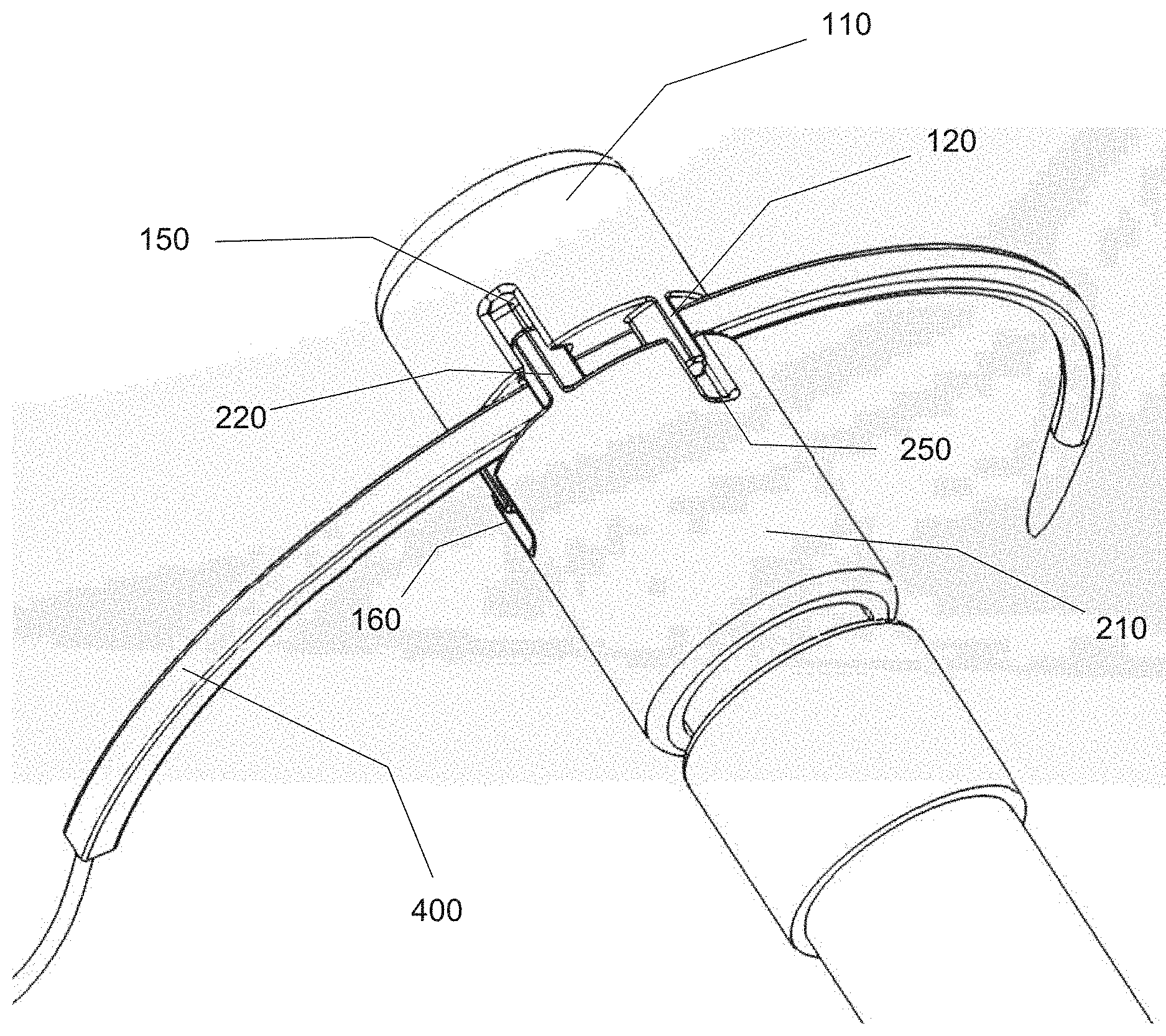
[0033] FIG. 1 represents a side view of the distal end of a first detailed embodiment of a needle holder according to the invention;
[0034] FIG. 2 represents a front view of the jaws carrying a curved needle according to this first detailed embodiment of a needle holder according to the invention;
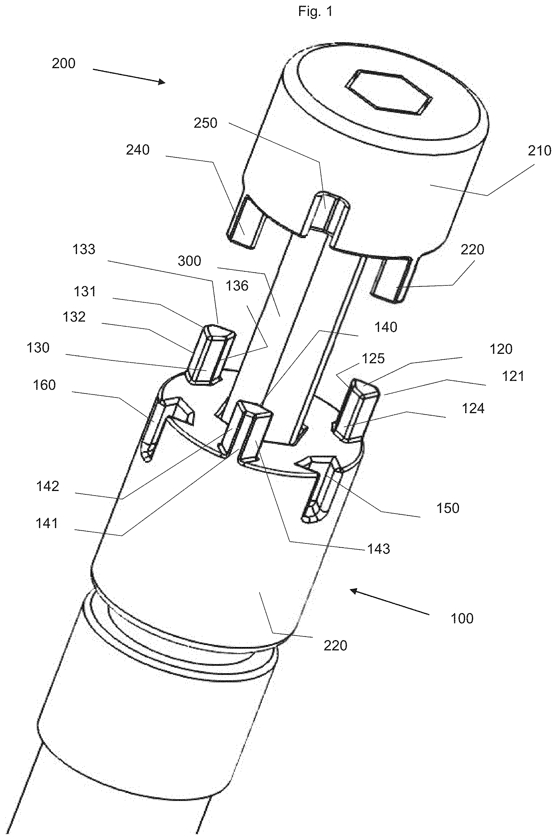
[0035] FIG. 3 represents an exploded overall view of this first detailed embodiment of a needle holder according to the invention;
[0036] FIG. 4 represents a rear three-quarter perspective view of the second jaw of this first detailed embodiment of a needle holder according to the invention;
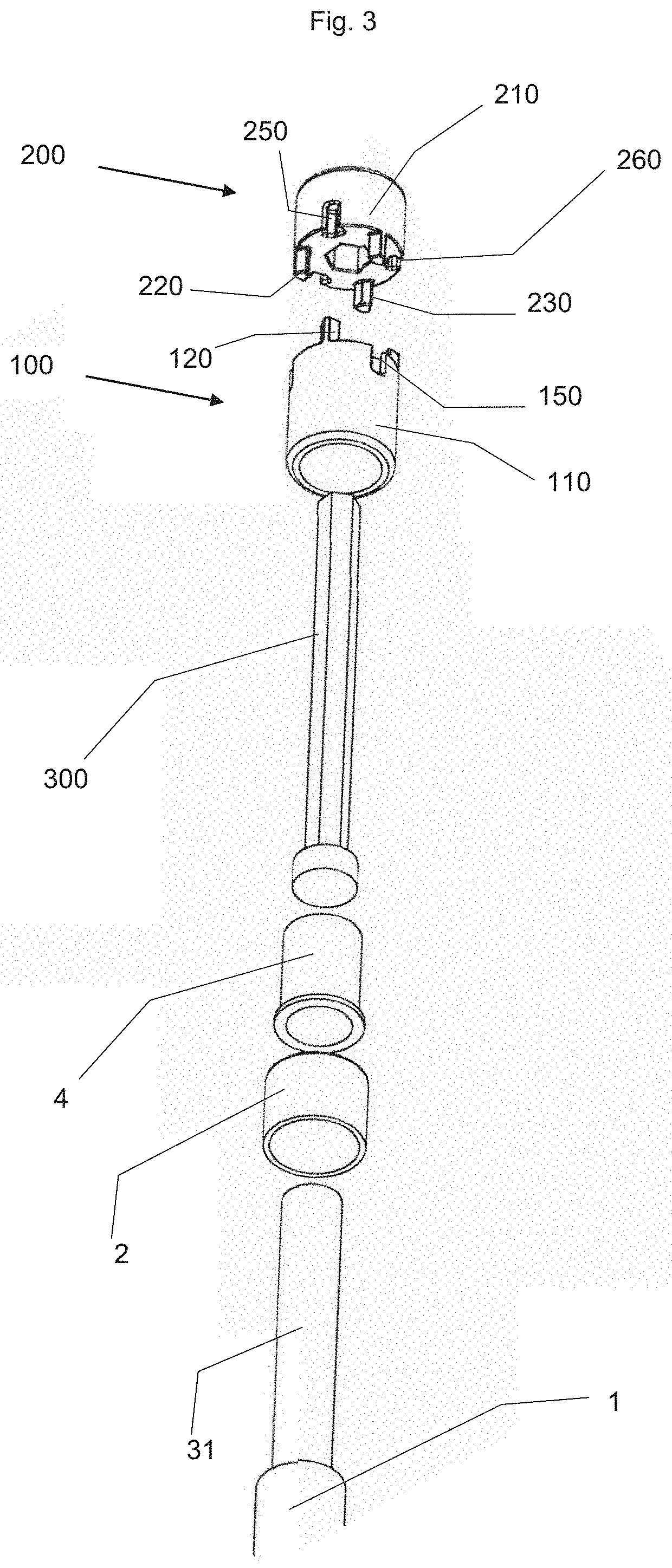
[0037] FIG. 5 represents a front three-quarter perspective view of the first jaw of this first detailed embodiment of a needle holder according to the invention;
[0038] FIG. 6 represents a cross-sectional view of the first jaw of this first detailed embodiment of a needle holder according to the invention;
[0039] FIG. 7 represents a front three-quarter perspective view of the first jaw of this first detailed embodiment of a needle holder according to the invention;
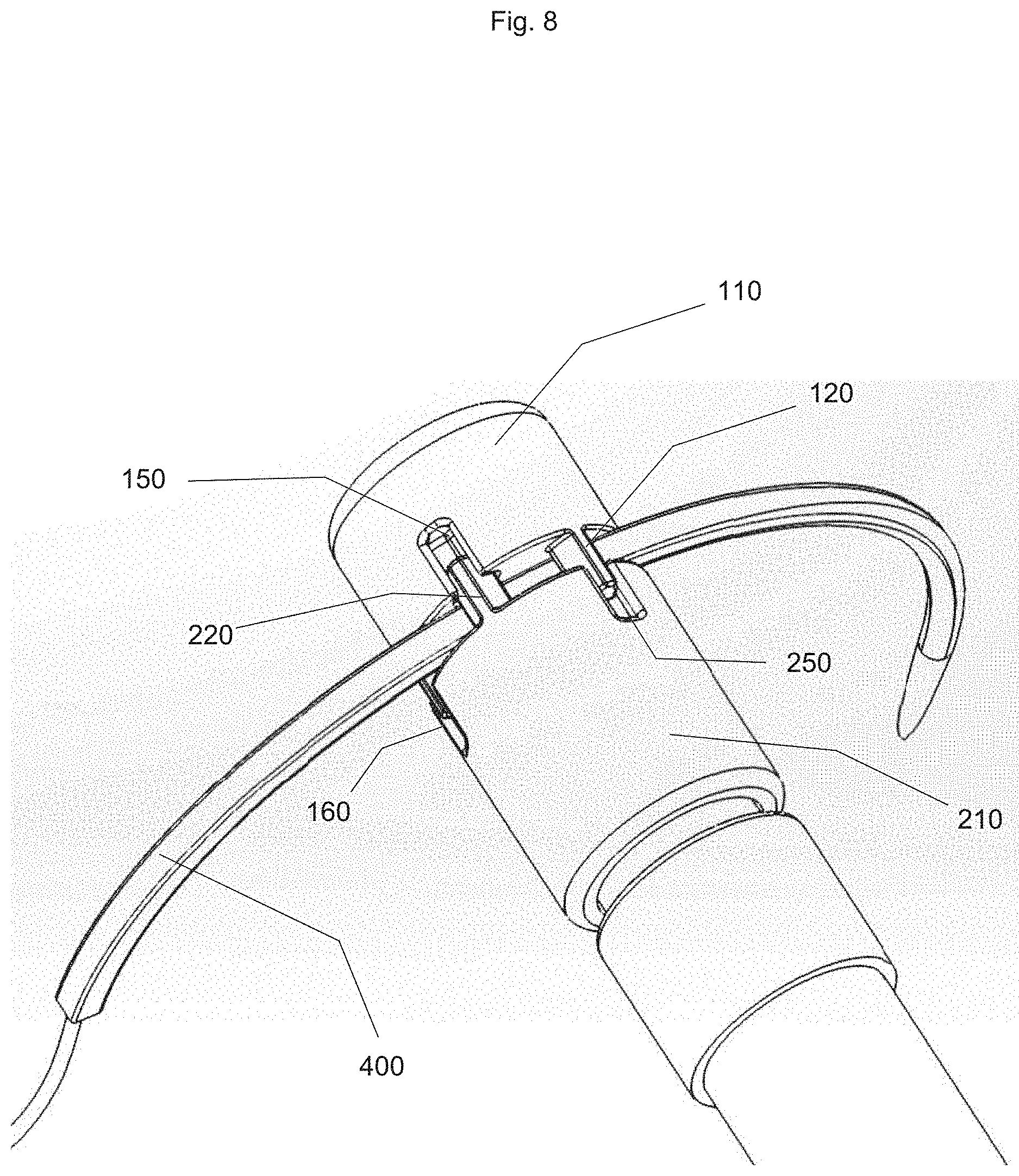
[0040] FIG. 8 represents a rear three-quarter perspective view of a needle holder according to the invention with a curved needle;
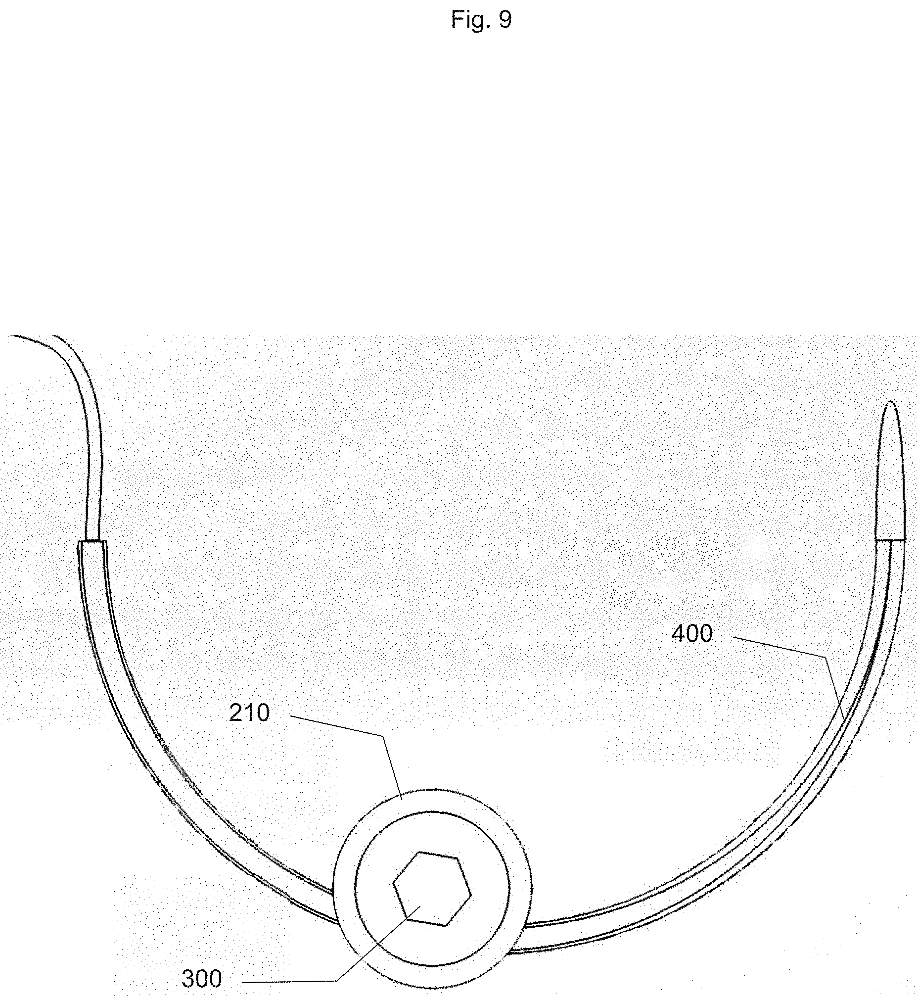
[0041] FIG. 9 represents a front view of a needle holder according to the invention with a curved needle;
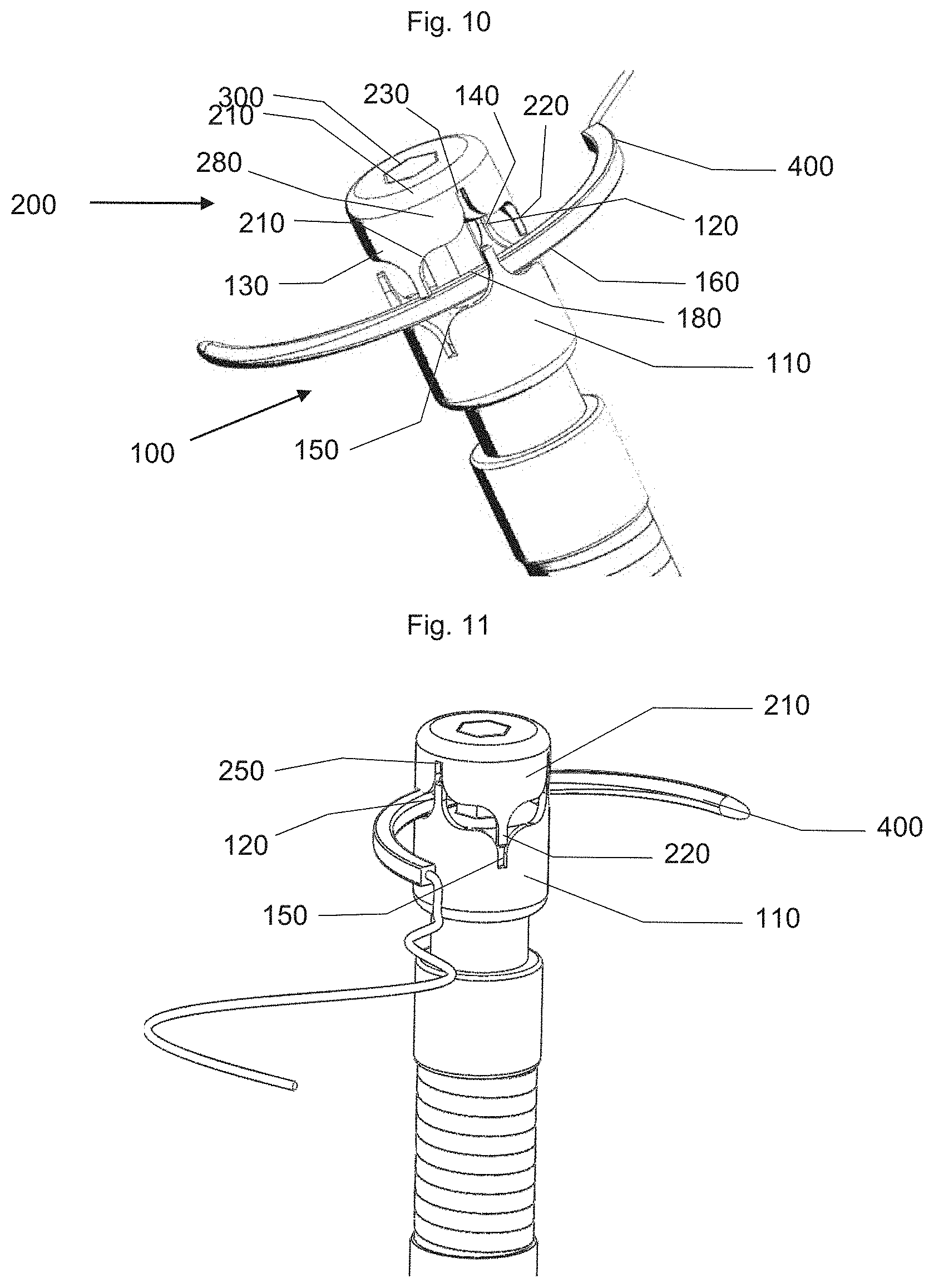
[0042] FIGS. 10 and 11 show perspective views of a second detailed embodiment with the jaws respectively in the open position and in the closed position;
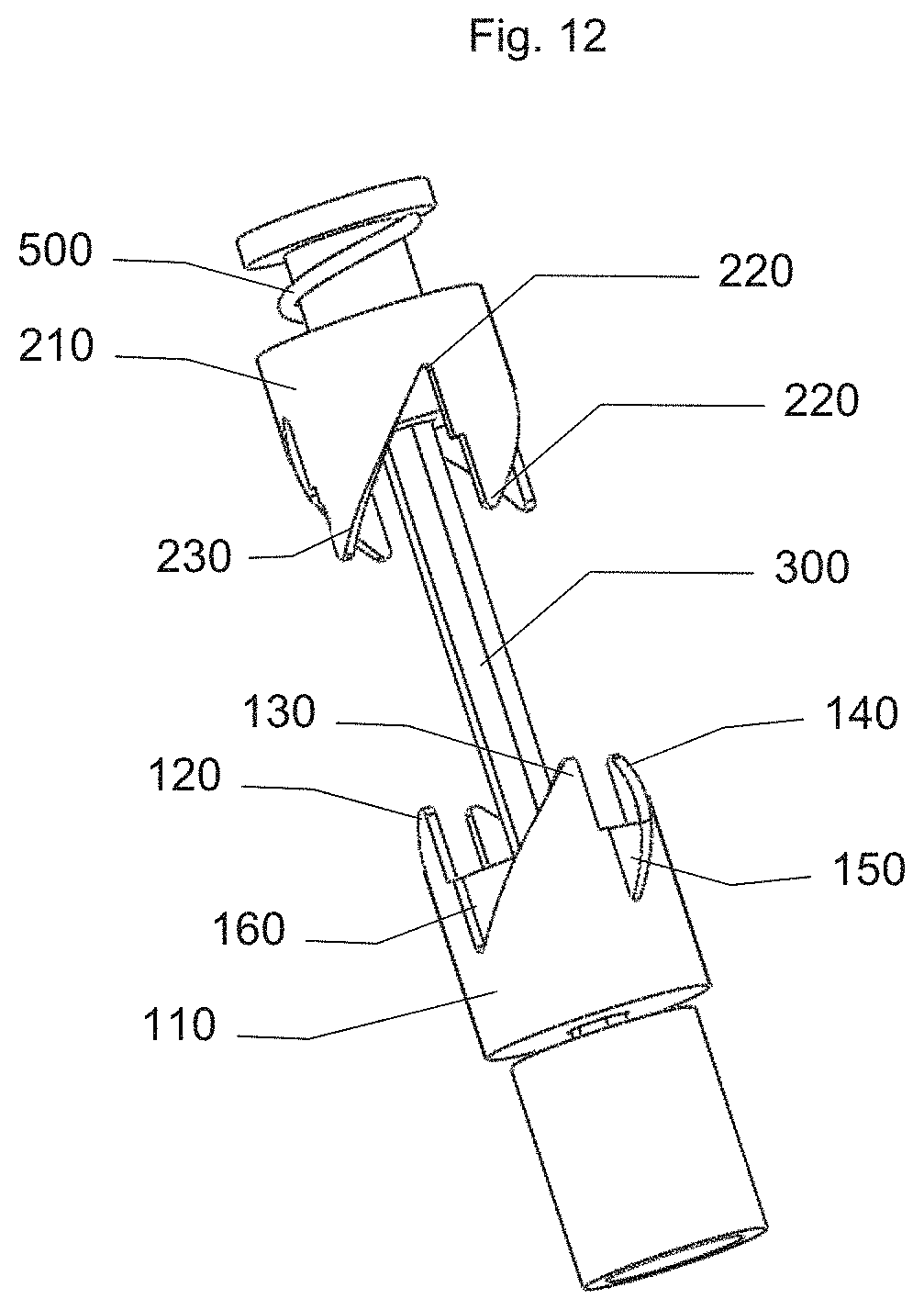
[0043] FIGS. 12 and 13 show perspective views of a third detailed embodiment with the jaws respectively in the open position and in the closed position;
[0044] FIG. 14 represents a perspective view of a needle holder according to a fourth embodiment of the invention with a curved needle;
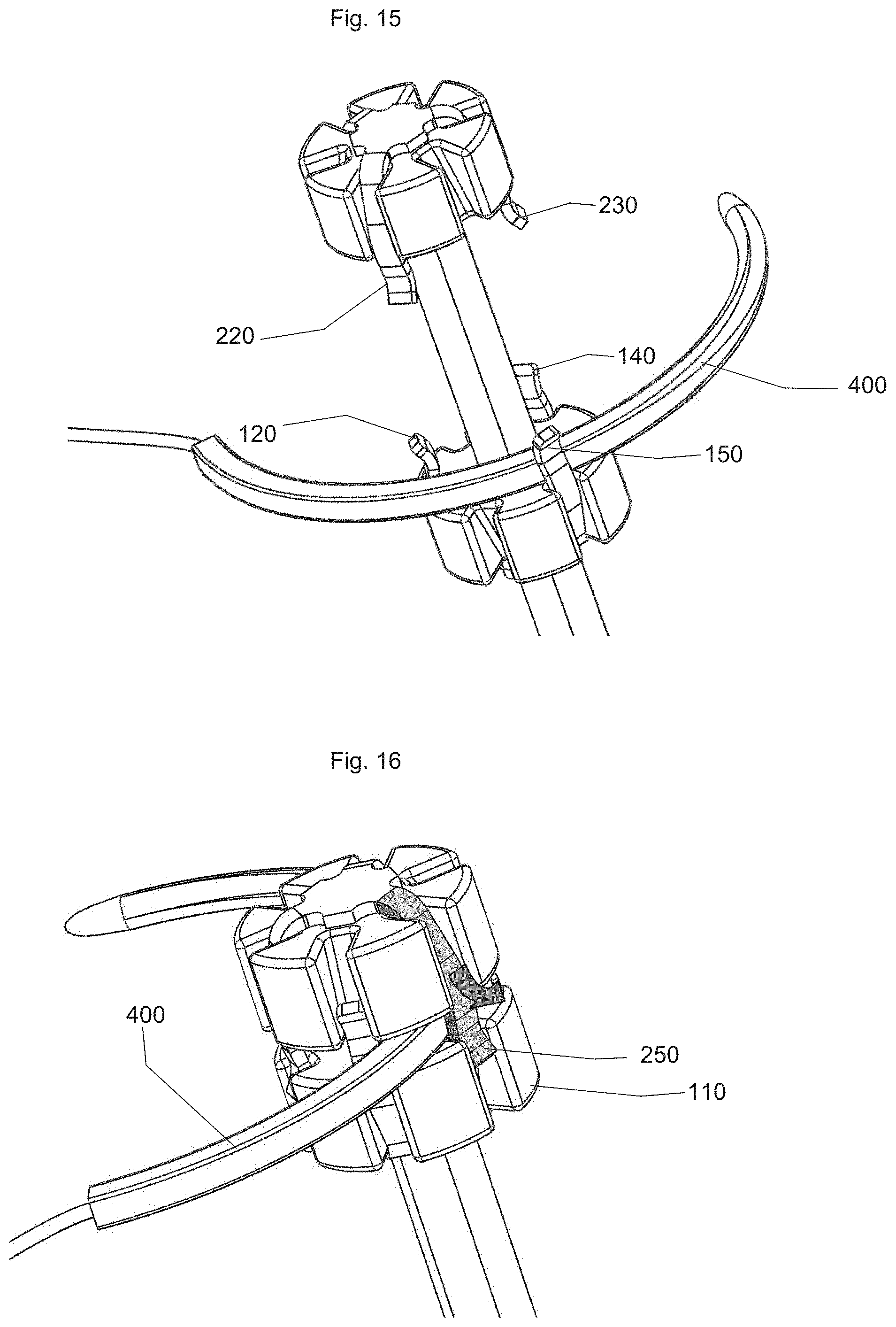
[0045] FIGS. 15 and 16 show perspective views of a fifth embodiment with the jaws respectively in the open position and in the closed position;
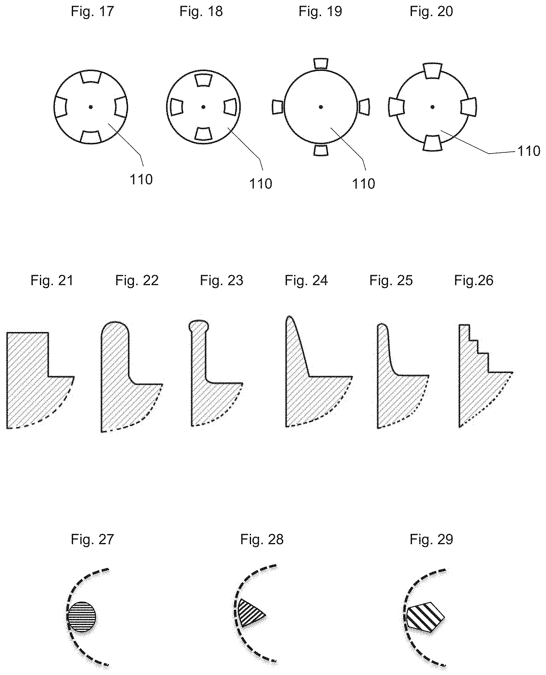
[0046] FIGS. 17 to 20 represent top views of different alternative embodiments of the implantation of the teeth;
[0047] FIGS. 21 to 26 show views along a radial sectional plane of various alternative embodiments of the teeth; and
[0048] FIGS. 27 to 29 show views along a transverse sectional plane of various alternative embodiments of the teeth.
DETAILED DESCRIPTION
Description of a First Detailed Embodiment
[0049] The first detailed embodiment will be described in more detail with reference to FIGS. 1 to 9. The needle holder according to the first detailed embodiment consists of a first coaxial jaw (100) and a second coaxial jaw (200) with a stem (300). The first jaw (100) is mounted on a connecting ring (4) provided at the distal end of a stem (1) which is equipped with a connecting ring (2). The first jaw (100) has a cylindrical metal body (110) defining a flat front surface (111) directed towards the second jaw (200). This cylindrical body (110) is surmounted by three teeth (120, 130, 140) spaced angularly at 120.degree. and arranged at the periphery of the front surface (111).
[0050] These teeth (120, 130, 140) have a pentagonal cross section, with: [0051] first semi-tubular sides (121, 131, 141) for extending the peripheral skirt of the cylindrical body (110); [0052] second and third sides (142, 143) forming an angle of between 30 and 70.degree. with respect to the tangential plane to the cylindrical body (110), on either side of the radial plane; [0053] fourth and fifth sides (124, 125) connecting the edges of the second and third sides (122, 132, 143, 123, 133, 143) to a median edge, respectively (136). These median edges (126, 136, 146) are located inside the second jaw, opposite the first sides (121, 131, 141). The radial plane passes through these central ridges (136) and a median line of the central ridges (136).
[0054] The second jaw (200) has a similar configuration, with three teeth (220, 230, 240) of the same shape as the teeth (120, 130, 140) of the first jaw (100), with a 60.degree. offset to create an alternation between the fixed teeth and the moving teeth. It has a central lumen (290) of polygonal section which is complementary to the cross section of the stem (300).
[0055] The fixed body (110) and the movable body (210) next to each tooth of the opposite jaw grooves (150, 160, 170; 250, 260, 270) whose cross section is complementary to the cross section of an opposite jaw tooth and the depth adapted to allow the engagement of a tooth of the opposite jaw when the fixed (100) and movable (200) jaws are in a close position. The cylindrical body (110) of the jaw (100) is traversed by a channel (190) of hexagonal section which is complementary to the hexagonal section of the stem (300) to allow movement along the longitudinal axis of this stem (300). The body (210) of the second jaw (200) is fixed at the end of this stem (300). The angular orientation between the first jaw (100) and the second jaw (200) is fixed in this first detailed embodiment.
[0056] In an embodiment where each of the jaws has three teeth, a curved needle is housed between the consecutive teeth (230, 140, 240, 120) and the stem (300), and is pressed against the blanks of the teeth and the stem to ensure a stable positioning enabling the needle to be moved in a perfectly controlled manner. The teeth (220, 230, 240) have polygonal cross sections. In the example described, they each have five facets (221 to 225, 231 to 232, 242, 244).
[0057] The front end of the needle holder may include a pear-shaped handle, enabling such gestures as: [0058] displacement of the second jaw (200) in spacing or approximation with respect to the first jaw (100) by applying pressure on the handle; [0059] rotational displacement of the needle holder by a rotation of the handle; [0060] axial displacement of the needle holder by a linear movement of the handle.
[0061] The displacement of the needle holder is thus homothetic to the movements of the surgeon which leads to a very intuitive and precise manipulation. For a laparoscopic variant the handle will have a "gun" shape. For a robotics variant, the front end of the needle holder will not include a handle but will be coupled to a motorized system.
Description of a Second Detailed Embodiment
[0062] FIGS. 10 and 11 illustrate another embodiment where the two fixed (100) and movable (200) jaws maintaining the curved needle (400) are made by cutting a stamped sheet. The first jaw (100) has a tubular skirt (110) extended by flarings (120, 130) forming the teeth, and by cut-outs (150) into complementary shapes to the teeth (220, 230) of the second jaw (200). In the same way, the second jaw (200) has a tubular skirt (210) extended by flarings (220, 230) forming the teeth, and by cut-outs (250) into complementary shapes to the teeth (120, 130) of the first jaw (100). The connection zone between a tooth and a cut-out has a point of inflection with an edge (180, 280) defining the bearing surface of the needle (400), and fulfilling the function of the transverse surface of the jaw of the first detailed embodiment.
Description of a Third Detailed Embodiment
[0063] FIGS. 12 and 13 illustrate a detailed embodiment, the jaws each having four teeth cut in a tubular skirt (110, 210), with a section, in a tangential, triangular plane, with an alternation with four complementary shaped cuts to receive the teeth of the opposite jaw. The second jaw can rotate angularly around the core (300). A return spring (500) tends to bring the opposing teeth against each other.
[0064] In this variant, the teeth of the upper jaw have a different initial position compared to the previously described variants. They are secured to the second jaw (200) by the spring (500). When the jaw closes, it can turn while sliding against the opposite teeth until the needle is held between the edges of the skirt. As the pressure continues, the cylindrical portion of the jaw continues to descend until the needle is tightened both up and down. This configuration can accommodate a plurality of needles.
Description of a Fourth Detailed Embodiment
[0065] FIG. 14 shows a perspective view of a fourth detailed embodiment with the jaws in the closed position. The jaws (100, 200) have elastically deformable bearings (180, 280) on which the teeth (220, 120) rest.
[0066] In this variant, the teeth can slide in the jaws (100, 200) to accommodate a variety of needles. When the jaws close, some teeth come into contact with their pendants on the opposite jaw. Teeth that come in contact with the needle retract into the jaw. The bearings (180, 280) consisting of a flexible material (rubber, silicone, . . . ) provide a spring function to all the teeth so that they all come out when the jaws are open.
Description of a Fifth Detailed Embodiment
[0067] FIGS. 15 and 16 show perspective views of a fifth detailed embodiment with the jaws respectively in the open position and in the closed position. According to this variant, the teeth (120, 130, 140, 220, 230, 240) are flexible and come to push the needle (400) inwards due to the elasticity. In this variant, the teeth can undergo elastic deformation to adapt to a variety of needles. When the jaws close, some teeth move apart and position themselves on the outer circumference of the needle, while remaining channelled into the groove of the opposite jaw.
Implantation of the Teeth
[0068] FIGS. 17 to 20 represent top views of different alternative embodiments of the implantation of the teeth. The teeth can be arranged at the edge of the jaw as shown in FIG. 17. In this case, the outer edge of the teeth is in line with the body of the jaw without asperity or hollow.
[0069] They can also be set back from the edge of the jaw as shown in FIG. 18. In this case they reduce the lateral size. They can also be arranged outside the jaw border, as shown in FIG. 19, to provide more attachment of a needle placed near the jaws. They can still be arranged straddling the edge of the jaw as shown in FIG. 20, for a compromise between improved attachment of the needle and a restricted lateral space.
Section of the Teeth
[0070] FIGS. 21 to 26 show views along a radial sectional plane of various alternative embodiments of the teeth. In the radial transverse plane the teeth may have a: [0071] rectangular section, with a flat or chamfered vertex, as shown in FIG. 21; [0072] rectangular section with a rounded top as shown in FIG. 22; [0073] rectangular section, with a flared top as shown in FIG. 23 to improve the retention of the needle; [0074] triangular section, as shown in FIG. 24 to bring the needle against the central core during the closure of the jaws; [0075] trapezoid section with increasing width towards the base of the tooth, with a curved inner edge as shown in FIG. 25, to ensure the guiding of the needle towards the centre during closure of the jaws; [0076] crenellated as shown in FIG. 26 to allow adaptation to different needle sizes.
Cross Section of the Teeth
[0077] FIGS. 27 to 29 show views along a transverse sectional plane of various alternative embodiments of the teeth. The section may be: [0078] circular as shown in FIG. 27; [0079] triangular with a rounded base as shown in FIG. 28, to present a central edge of support against the surface of the needle; [0080] pentagonal as shown in FIG. 29.
* * * * *
D00000
D00001
D00002
D00003
D00004
D00005
D00006
D00007
D00008
D00009
D00010
D00011
D00012

D00013
D00014
XML
uspto.report is an independent third-party trademark research tool that is not affiliated, endorsed, or sponsored by the United States Patent and Trademark Office (USPTO) or any other governmental organization. The information provided by uspto.report is based on publicly available data at the time of writing and is intended for informational purposes only.
While we strive to provide accurate and up-to-date information, we do not guarantee the accuracy, completeness, reliability, or suitability of the information displayed on this site. The use of this site is at your own risk. Any reliance you place on such information is therefore strictly at your own risk.
All official trademark data, including owner information, should be verified by visiting the official USPTO website at www.uspto.gov. This site is not intended to replace professional legal advice and should not be used as a substitute for consulting with a legal professional who is knowledgeable about trademark law.