Apparatus And Method For A Sit-stand Workstation
Elliott; Jared L.
U.S. patent application number 16/004167 was filed with the patent office on 2019-12-12 for apparatus and method for a sit-stand workstation. The applicant listed for this patent is Health Postures, LLC. Invention is credited to Jared L. Elliott.
| Application Number | 20190374024 16/004167 |
| Document ID | / |
| Family ID | 68765336 |
| Filed Date | 2019-12-12 |


View All Diagrams
| United States Patent Application | 20190374024 |
| Kind Code | A1 |
| Elliott; Jared L. | December 12, 2019 |
APPARATUS AND METHOD FOR A SIT-STAND WORKSTATION
Abstract
The present invention provides methods and a workstation that includes a work table, wherein the work table includes: a first work surface and a second work surface, wherein the second work surface is configured to have vertical movement such that the second work surface can be selectively placed in a first plurality of vertical positions relative to the first work surface, and a first motor operatively coupled to the second work surface and configured to power the vertical movement of the second work surface; and a plurality of legs coupled to the work table, wherein the plurality of legs is configured to support the work table above a ground surface, and wherein the plurality of legs includes a lift mechanism configured to raise and lower the plurality of legs such that the work table can be selectively placed in a plurality of height configurations relative to the ground surface.
| Inventors: | Elliott; Jared L.; (Prior Lake, MN) | ||||||||||
| Applicant: |
|
||||||||||
|---|---|---|---|---|---|---|---|---|---|---|---|
| Family ID: | 68765336 | ||||||||||
| Appl. No.: | 16/004167 | ||||||||||
| Filed: | June 8, 2018 |
| Current U.S. Class: | 1/1 |
| Current CPC Class: | A47B 2200/0062 20130101; A47B 13/088 20130101; A47B 2009/185 20130101; A47B 2009/006 20130101; A47B 13/081 20130101; A47B 21/02 20130101; A47B 2200/0056 20130101; A47B 9/00 20130101 |
| International Class: | A47B 21/02 20060101 A47B021/02; A47B 9/00 20060101 A47B009/00; A47B 13/08 20060101 A47B013/08 |
Claims
1. A workstation comprising: a work table, wherein the work table includes: a plurality of work surfaces including a first work surface and a second work surface, wherein the second work surface is configured to have vertical movement relative to the first work surface such that the second work surface can be selectively placed in a first plurality of vertical positions relative to the first work surface, and a first motor operatively coupled to the second work surface and configured to power the vertical movement of the second work surface; and a plurality of legs coupled to the work table, wherein the plurality of legs is configured to support the work table above a ground surface, and wherein the plurality of legs includes a lift mechanism configured to increase or decrease a vertical extent of the plurality of legs such that the work table can be selectively placed in a plurality of height configurations relative to the ground surface.
2. The workstation of claim 1, wherein the first plurality of vertical positions of the second work surface includes a lowest vertical position, and wherein the second work surface is flush with the first work surface when the second work surface is in the lowest vertical position.
3. The workstation of claim 1, wherein the plurality of work surfaces further includes a third work surface that is in an offset-height configuration relative to the first work surface.
4. The workstation of claim 1, wherein the plurality of work surfaces further includes a third work surface that is in an offset-height configuration relative to the first work surface, wherein the first plurality of vertical positions of the second work surface includes a lowest vertical position, and wherein the second work surface is flush with the third work surface when the second work surface is in the lowest vertical position.
5. The workstation of claim 1, wherein the plurality of work surfaces further includes a third work surface, wherein the third work surface is configured to have vertical movement such that the third work surface can be selectively placed in a second plurality of vertical positions relative to the first work surface, and wherein the first motor is further configured to power the vertical movement of the third work surface such that the vertical movement of the third work surface is simultaneous with the vertical movement of the second work surface.
6. The workstation of claim 1, wherein the plurality of work surfaces further includes a third work surface, wherein the third work surface is configured to have vertical movement such that the third work surface can be selectively placed in a second plurality of vertical positions relative to the first work surface, the work table further including: a second motor operatively coupled to the third work surface and configured to power the vertical movement of the third work surface such that the vertical movement of the third work surface is independent of the vertical movement of the second work surface.
7. The workstation of claim 1, wherein the plurality of work surfaces further includes a third work surface, wherein the third work surface is configured to have vertical movement such that the third work surface can be selectively placed in a second plurality of vertical positions relative to the first work surface, wherein the second work surface is flush with the third work surface and in an offset-height configuration relative to the first work surface when both the first work surface and the second work surface are in a lowest vertical position.
8. The workstation of claim 1, wherein the plurality of legs includes a first leg coupled to a first side of the work table and a second leg coupled to a second side of the work table, the workstation further comprising: a horizontal bracket coupled between the first leg and the second leg in order to provide side-to-side stabilization for the workstation.
9. The workstation of claim 1, wherein the work table further includes an operator switch configured to provide user control for the first motor.
10. The workstation of claim 1, wherein the work table further includes: a first operator switch configured to provide user control for the first motor, and a second operator switch configured to provide user control for the lift mechanism of the plurality of legs.
11. The workstation of claim 1, wherein the first plurality of vertical positions of the second work surface includes a lowest vertical position, wherein the second work surface is flush with the first work surface when the second work surface is in the lowest vertical position, and wherein the work table further includes an operator switch configured to provide user control for the first motor.
12. The workstation of claim 1, wherein the first plurality of vertical positions of the second work surface includes a lowest vertical position, wherein the second work surface is flush with the first work surface when the second work surface is in the lowest vertical position, wherein the plurality of legs includes a first leg coupled to a first side of the work table and a second leg coupled to a second side of the work table, the workstation further comprising: a horizontal bracket coupled between the first leg and the second leg in order to provide side-to-side stabilization for the workstation.
13. The workstation of claim 1, wherein the plurality of work surfaces further includes a third work surface that is in an offset-height configuration relative to the first work surface, wherein the plurality of legs includes a first leg coupled to a first side of the work table and a second leg coupled to a second side of the work table, the workstation further comprising: a horizontal bracket coupled between the first leg and the second leg in order to provide side-to-side stabilization for the workstation.
14. The workstation of claim 1, wherein the plurality of work surfaces further includes a third work surface, wherein the third work surface is configured to have vertical movement such that the third work surface can be selectively placed in a second plurality of vertical positions relative to the first work surface, the work table further including: a second motor operatively coupled to the third work surface and configured to power the vertical movement of the third work surface such that the vertical movement of the third work surface is independent of the vertical movement of the second work surface, a first operator switch configured to provide user control for the first motor, a second operator switch configured to provide user control for the second motor, and a third operator switch configured to provide user control for the lift mechanism of the plurality of legs.
15. A method for forming a workstation comprising: providing a work table that includes a plurality of work surfaces including a first work surface and a second work surface, wherein the second work surface is configured to have vertical movement relative to the first work surface such that the second work surface can be selectively placed in a first plurality of vertical positions relative to the first work surface; providing a first motor; operatively coupling the first motor to the second work surface in order to provide power for the vertical movement of the second work surface; providing a plurality of legs; and coupling the plurality of legs to the work table, wherein the plurality of legs supports the work table above a ground surface, and wherein the plurality of legs includes a lift mechanism configured to increase or decrease a vertical extent of the plurality of legs such that the work table can be selectively placed in a plurality of height configurations relative to the ground surface.
16. The method of claim 16, wherein the plurality of work surfaces further includes a third work surface, wherein the third work surface is configured to have vertical movement such that the third work surface can be selectively placed in a second plurality of vertical positions relative to the first work surface, the method further comprising: providing a second motor; and operatively coupling the second motor to the third work surface in order to provide power for the vertical movement of the third work surface such that the vertical movement of the third work surface is independent of the vertical movement of the second work surface.
17. The method of claim 16, wherein the plurality of work surfaces further includes a third work surface, wherein the third work surface is configured to have vertical movement such that the third work surface can be selectively placed in a second plurality of vertical positions relative to the first work surface, the method further comprising: operatively coupling the first motor to the third work surface in order to provide power for the vertical movement of the third work surface such that the vertical movement of the third work surface is simultaneous with the vertical movement of the second work surface.
18. The method of claim 16, wherein the plurality of legs includes a first leg and a second leg, wherein the coupling of the plurality of legs to the work table includes attaching the first leg to a first side of the work table and attaching the second leg to a second side of the work table, the method further comprising: providing a horizontal bracket; and connecting the horizontal bracket between the first leg and the second leg in order to provide side-to-side stabilization for the workstation.
19. The method of claim 16, further comprising: providing an operator switch; electrically connecting the operator switch to the first motor in order to provide user control for the first motor; and attaching the operator switch to the work table.
20. An apparatus comprising: a work table that includes a plurality of work surfaces; means for raising and lowering at least one of the plurality of work surfaces relative to another one of the plurality of work surfaces; and means for supporting the work table above a ground surface, wherein the means for supporting the work table includes means for changing a height of the means for supporting.
Description
FIELD OF THE INVENTION
[0001] The present invention relates to devices and methods for workstations, and in particular to apparatuses and methods for a workstation that has an overall height adjustment, as well as independent surface-height adjustments, in order to provide a user with a plurality of sitting and standing positions when using the workstation.
BACKGROUND OF THE INVENTION
[0002] U.S. Pat. No. 9,049,923 by Nico Vincent Delagey, et al., titled "POWERED HEIGHT ADJUSTABLE DESKTOP," issued on Jun. 9, 2015 (hereinafter, "Delagey et al."), and is incorporated herein by reference. Delagey et al. describe a powered height adjustable desktop having a base with a fixed peripheral wall defining a cavity and a cover defining a horizontal work surface. A lift mechanism supports the cover relative to the base. The lift mechanism includes a linkage with at least one pair of lift arms pivotably connecting each side of the base to a respective side of the cover and a powered actuator attached to the base and operatively connected to the linkage. The actuator selectively activates the linkage to rotate the lift arms from a relatively horizontal position to at least one substantially fixed upright position, thereby raising the work surface from a sitting height to a standing height. At the sitting height, the cover rests upon the peripheral wall to fully enclose the cavity. At the standing height, the cover is spaced above and offset forward of the base.
[0003] U.S. Pat. No. 9,332,839 by John Frederick Ringlein, titled "DESK MOUNTED VERTICALLY ADJUSTABLE STAND UP DESK," issued on May 10, 2016 (hereinafter, "Ringlein"), and is incorporated herein by reference. Ringlein describes a desk mounted vertically adjustable stand up desk that allows a conventional desk to be easily and quickly converted to a stand up desk for the user. The desk mounted vertically adjustable stand up desk includes a base plate adapted to be supported on a desk surface; a tower vertically extending from the base plate; a stand up desk surface member moveably mounted on the tower and configured to be vertically adjustable relative to the base plate; and a lock member coupled to the tower and configured to secure the stand up desk surface member in a desired user selected vertical position.
[0004] U.S. Pat. No. 9,486,070 by Jean-Paul Labrosse, et al., titled "HEIGHT-ADJUSTABLE SUPPORT SURFACE AND SYSTEM FOR ENCOURAGING HUMAN MOVEMENT AND PROMOTING WELLNESS," issued on Nov. 8, 2016 (hereinafter, "Labrosse et al."), and is incorporated herein by reference. Labrosse et al. describe a sit/stand workstation that includes a worktop that includes a powered drive and is moveable between a sitting height and a standing height. During use, a controller moves the worktop up and down following a user-defined schedule and uses sensors, such as a pressure mat, to detect how well the user follows the schedule and biometric indicators that convey fatigue and user energy level. In response to this monitored user information, the controller changes time, duration, and/or frequency of the schedule to better meet the abilities and fitness of the user and also to help encourage the user to continue regular use of both sitting height and standing height workstation positions. Sounds, voice, lights, colors, and numerical information are used to help encourage the user in use of the sit/stand workstation.
[0005] There is a need for an improved system and method for a sit-stand workstation.
SUMMARY OF THE INVENTION
[0006] The present invention provides a workstation that includes a work table, wherein the work table includes: a plurality of work surfaces including a first work surface and a second work surface, wherein the second work surface is configured to have vertical movement such that the second work surface can be selectively placed in a first plurality of vertical positions relative to the first work surface, and a first motor operatively coupled to the second work surface and configured to power the vertical movement of the second work surface; and a plurality of legs coupled to the work table, wherein the plurality of legs is configured to support the work table above a ground surface, and wherein the plurality of legs includes a lift mechanism configured to raise and lower the plurality of legs such that the work table can be selectively placed in a plurality of height configurations relative to the ground surface.
[0007] In some embodiments, the present invention provides a method for forming a workstation that includes providing a work table that includes a plurality of work surfaces including a first work surface and a second work surface, wherein the second work surface is configured to have vertical movement such that the second work surface can be selectively placed in a first plurality of vertical positions relative to the first work surface; providing a first motor; operatively coupling the first motor to the second work surface in order to provide power for the vertical movement of the second work surface; providing a plurality of legs; and coupling the plurality of legs to the work table, wherein the plurality of legs supports the work table above a ground surface, and wherein the plurality of legs includes a lift mechanism configured to raise and lower the plurality of legs such that the work table can be selectively placed in a plurality of height configurations relative to the ground surface.
BRIEF DESCRIPTION OF THE FIGURES
[0008] FIG. 1A-1 is a perspective view of a sit-stand workstation 101, according to some embodiments of the present invention.
[0009] FIG. 1A-2 is a perspective view of sit-stand workstation 101 with adjustable surface 135 in a raised position, according to some embodiments of the present invention.
[0010] FIG. 1A-3 is a perspective view of sit-stand workstation 101 with legs 110 in a shortened position and adjustable surface 135 in a lowered position, according to some embodiments of the present invention.
[0011] FIG. 1A-4 is a perspective view of sit-stand workstation 101 with legs 110 in a shortened position and adjustable surface 135 in a raised position, according to some embodiments of the present invention.
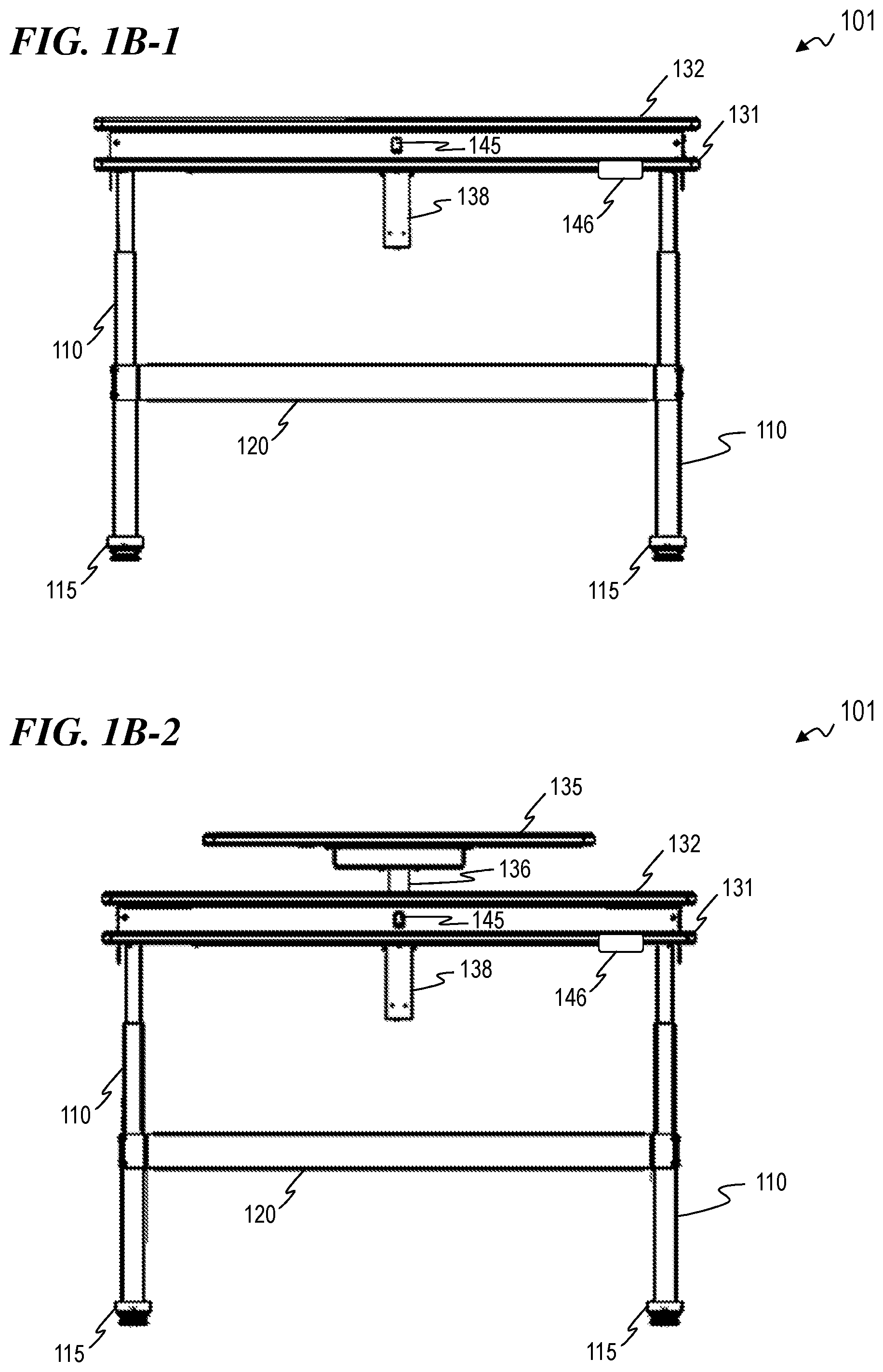
[0012] FIG. 1B-1 is a front view of sit-stand workstation 101, according to some embodiments of the present invention.
[0013] FIG. 1B-2 is a front view of sit-stand workstation 101 with adjustable surface 135 in a raised position, according to some embodiments of the present invention.
[0014] FIG. 1B-3 is a front view of sit-stand workstation 101 with legs 110 in a shortened position and adjustable surface 135 in a lowered position, according to some embodiments of the present invention.
[0015] FIG. 1B-4 is a front view of sit-stand workstation 101 with legs 110 in a shortened position and adjustable surface 135 in a raised position, according to some embodiments of the present invention.
[0016] FIG. 1C-1 is a rear view of sit-stand workstation 101, according to some embodiments of the present invention.
[0017] FIG. 1C-2 is a rear view of sit-stand workstation 101 with adjustable surface 135 in a raised position, according to some embodiments of the present invention.
[0018] FIG. 1C-3 is a rear view of sit-stand workstation 101 with legs 110 in a shortened position and adjustable surface 135 in a lowered position, according to some embodiments of the present invention.
[0019] FIG. 1C-4 is a rear view of sit-stand workstation 101 with legs 110 in a shortened position and adjustable surface 135 in a raised position, according to some embodiments of the present invention.
[0020] FIG. 1D-1 is a left-side view of sit-stand workstation 101, according to some embodiments of the present invention.
[0021] FIG. 1D-2 is a left-side view of sit-stand workstation 101 with adjustable surface 135 in a raised position, according to some embodiments of the present invention.
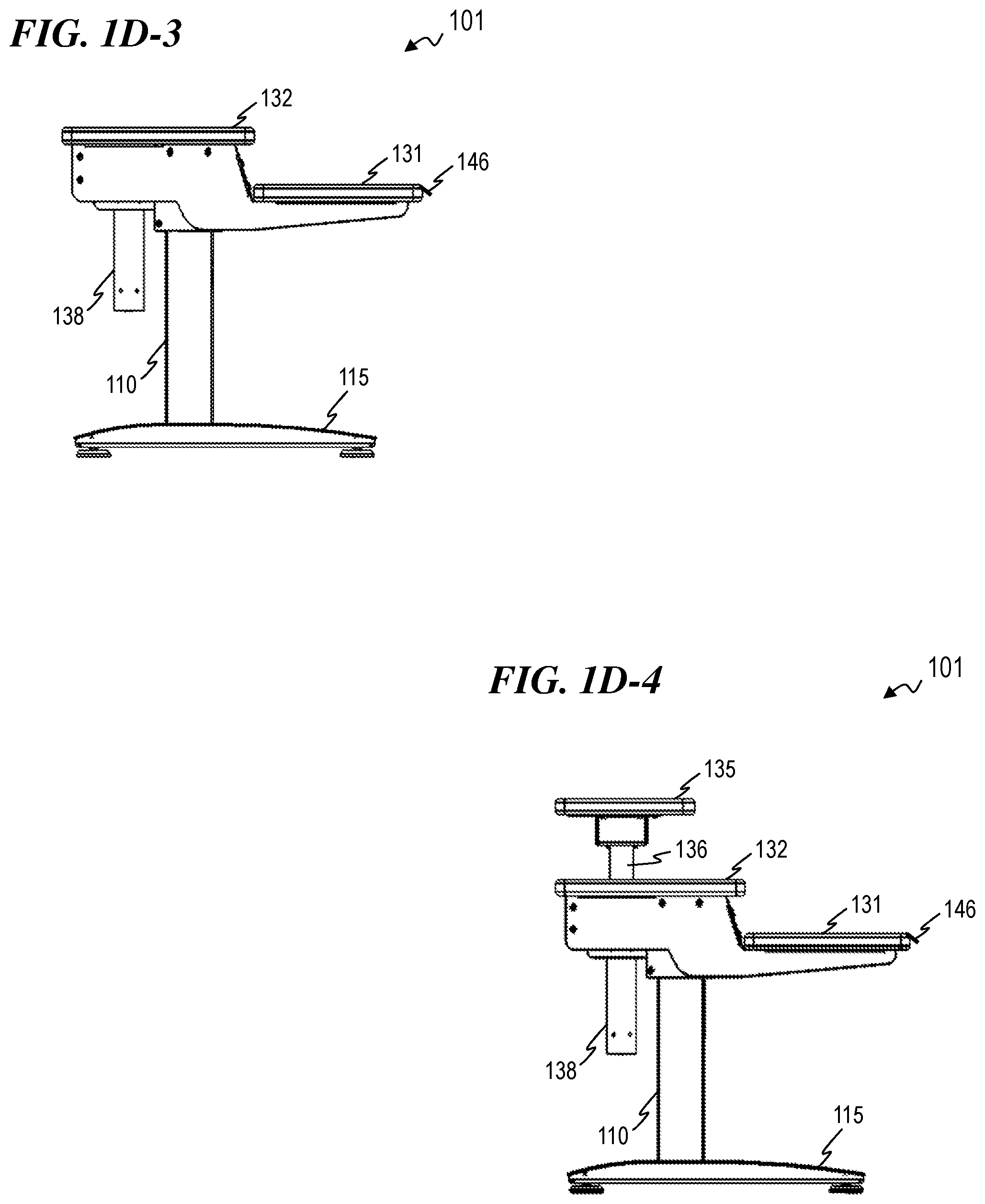
[0022] FIG. 1D-3 is a left-side view of sit-stand workstation 101 with legs 110 in a shortened position and adjustable surface 135 in a lowered position, according to some embodiments of the present invention.
[0023] FIG. 1D-4 is a left-side view of sit-stand workstation 101 with legs 110 in a shortened position and adjustable surface 135 in a raised position, according to some embodiments of the present invention.
[0024] FIG. 1E-1 is a right-side view of sit-stand workstation 101, according to some embodiments of the present invention.
[0025] FIG. 1E-2 is a right-side view of sit-stand workstation 101 with adjustable surface 135 in a raised position, according to some embodiments of the present invention.
[0026] FIG. 1E-3 is a right-side view of sit-stand workstation 101 with legs 110 in a shortened position and adjustable surface 135 in a lowered position, according to some embodiments of the present invention.
[0027] FIG. 1E-4 is a right-side view of sit-stand workstation 101 with legs 110 in a shortened position and adjustable surface 135 in a raised position, according to some embodiments of the present invention.
[0028] FIG. 1E-5 is a right-side view of sit-stand workstation 101 with adjustable surface 135 in a raised position and showing various dimensions for workstation 101, according to some embodiments of the present invention.
[0029] FIG. 1E-6 is a right-side view of sit-stand workstation 101 with legs 110 in a shortened position, adjustable surface 135 in a raised position, and showing various dimensions for workstation 101, according to some embodiments of the present invention.
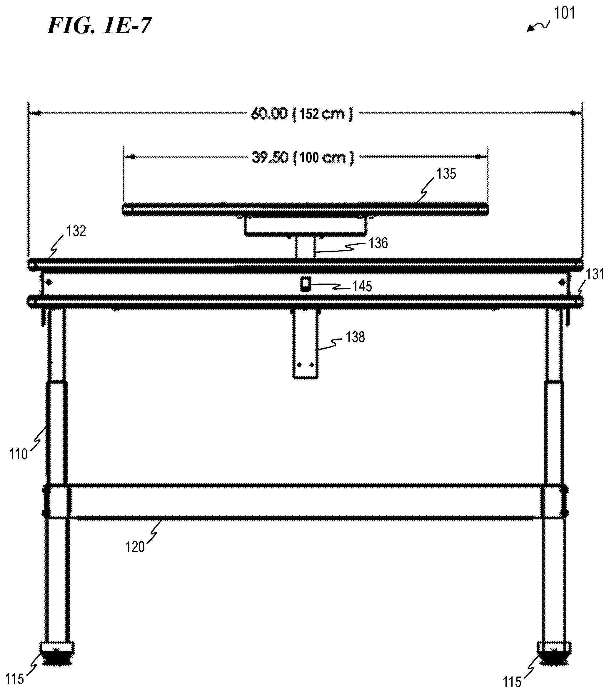
[0030] FIG. 1E-7 is a front view of sit-stand workstation 101 with adjustable surface 135 in a raised position and showing various dimensions for workstation 101, according to some embodiments of the present invention.
[0031] FIG. 1F is a plan view of sit-stand workstation 101, according to some embodiments of the present invention.
[0032] FIG. 1G is a bottom view of sit-stand workstation 101, according to some embodiments of the present invention.
[0033] FIG. 2A-1 is a perspective view of a sit-stand workstation 201, according to some embodiments of the present invention.
[0034] FIG. 2A-2 is a perspective view of sit-stand workstation 201 with adjustable surface 135 in a raised position, according to some embodiments of the present invention.
[0035] FIG. 2A-3 is a perspective view of sit-stand workstation 201 with legs 110 in a shortened position and adjustable surface 135 in a lowered position, according to some embodiments of the present invention.
[0036] FIG. 2A-4 is a perspective view of sit-stand workstation 201 with legs 110 in a shortened position and adjustable surface 135 in a raised position, according to some embodiments of the present invention.
[0037] FIG. 2B-1 is a front view of sit-stand workstation 201, according to some embodiments of the present invention.
[0038] FIG. 2B-2 is a front view of sit-stand workstation 201 with adjustable surface 135 in a raised position, according to some embodiments of the present invention.
[0039] FIG. 2B-3 is a front view of sit-stand workstation 201 with legs 110 in a shortened position and adjustable surface 135 in a lowered position, according to some embodiments of the present invention.
[0040] FIG. 2B-4 is a front view of sit-stand workstation 201 with legs 110 in a shortened position and adjustable surface 135 in a raised position, according to some embodiments of the present invention.
[0041] FIG. 2C-1 is a rear view of sit-stand workstation 201, according to some embodiments of the present invention.
[0042] FIG. 2C-2 is a rear view of sit-stand workstation 201 with adjustable surface 135 in a raised position, according to some embodiments of the present invention.
[0043] FIG. 2C-3 is a rear view of sit-stand workstation 201 with legs 110 in a shortened position and adjustable surface 135 in a lowered position, according to some embodiments of the present invention.
[0044] FIG. 2C-4 is a rear view of sit-stand workstation 201 with legs 110 in a shortened position and adjustable surface 135 in a raised position, according to some embodiments of the present invention.
[0045] FIG. 2D-1 is a left-side view of sit-stand workstation 201, according to some embodiments of the present invention.
[0046] FIG. 2D-2 is a left-side view of sit-stand workstation 201 with adjustable surface 135 in a raised position, according to some embodiments of the present invention.
[0047] FIG. 2D-3 is a left-side view of sit-stand workstation 201 with legs 110 in a shortened position and adjustable surface 135 in a lowered position, according to some embodiments of the present invention.
[0048] FIG. 2D-4 is a left-side view of sit-stand workstation 201 with legs 110 in a shortened position and adjustable surface 135 in a raised position, according to some embodiments of the present invention.
[0049] FIG. 2E-1 is a right-side view of sit-stand workstation 201, according to some embodiments of the present invention.
[0050] FIG. 2E-2 is a right-side view of sit-stand workstation 201 with adjustable surface 140 in a raised position, according to some embodiments of the present invention.
[0051] FIG. 2E-3 is a right-side view of sit-stand workstation 201 with legs 110 in a shortened position and adjustable surface 135 in a lowered position, according to some embodiments of the present invention.
[0052] FIG. 2E-4 is a right-side view of sit-stand workstation 201 with legs 110 in a shortened position and adjustable surface 135 in a raised position, according to some embodiments of the present invention.
[0053] FIG. 2F is a plan view of sit-stand workstation 201, according to some embodiments of the present invention.
[0054] FIG. 2G is a bottom view of sit-stand workstation 201, according to some embodiments of the present invention.
[0055] FIG. 3A-1 is a perspective view of a sit-stand workstation 301, according to some embodiments of the present invention.
[0056] FIG. 3A-2 is a perspective view of sit-stand workstation 301 with adjustable surfaces 335.1 and 335.2 in a raised position, according to some embodiments of the present invention.
[0057] FIG. 3A-3 is a perspective view of sit-stand workstation 301 with legs 110 in a shortened position and adjustable surfaces 335.1 and 335.2 in a lowered position, according to some embodiments of the present invention.
[0058] FIG. 3A-4 is a perspective view of sit-stand workstation 301 with legs 110 in a shortened position and adjustable surfaces 335.1 and 335.2 in a raised position, according to some embodiments of the present invention.
[0059] FIG. 3B-1 is a front view of sit-stand workstation 301, according to some embodiments of the present invention.
[0060] FIG. 3B-2 is a front view of sit-stand workstation 301 with adjustable surfaces 335.1 and 335.2 in a raised position, according to some embodiments of the present invention.
[0061] FIG. 3B-3 is a front view of sit-stand workstation 301 with legs 110 in a shortened position and adjustable surfaces 335.1 and 335.2 in a lowered position, according to some embodiments of the present invention.
[0062] FIG. 3B-4 is a front view of sit-stand workstation 301 with legs 110 in a shortened position and adjustable surfaces 335.1 and 335.2 in a raised position, according to some embodiments of the present invention.
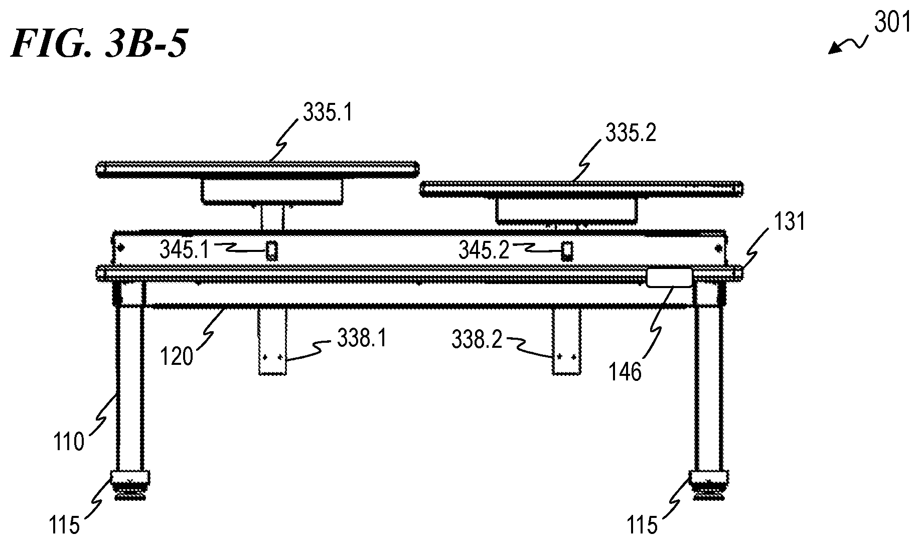
[0063] FIG. 3B-5 is a front view of sit-stand workstation 301 with legs 110 in a shortened position and adjustable surface 335.1 in a first raised position and adjustable surface 335.2 in a second raised position, according to some embodiments of the present invention.
[0064] FIG. 3C-1 is a rear view of sit-stand workstation 301, according to some embodiments of the present invention.
[0065] FIG. 3C-2 is a rear view of sit-stand workstation 301 with adjustable surfaces 335.1 and 335.2 in a raised position, according to some embodiments of the present invention.
[0066] FIG. 3C-3 is a rear view of sit-stand workstation 301 with legs 110 in a shortened position and adjustable surfaces 335.1 and 335.2 in a lowered position, according to some embodiments of the present invention.
[0067] FIG. 3C-4 is a rear view of sit-stand workstation 301 with legs 110 in a shortened position and adjustable surfaces 335.1 and 335.2 in a raised position, according to some embodiments of the present invention.
[0068] FIG. 3D-1 is a left-side view of sit-stand workstation 301, according to some embodiments of the present invention.
[0069] FIG. 3D-2 is a left-side view of sit-stand workstation 301 with adjustable surfaces 335.1 and 335.2 in a raised position, according to some embodiments of the present invention.
[0070] FIG. 3D-3 is a left-side view of sit-stand workstation 301 with legs 110 in a shortened position and adjustable surfaces 335.1 and 335.2 in a lowered position, according to some embodiments of the present invention.
[0071] FIG. 3D-4 is a left-side view of sit-stand workstation 301 with legs 110 in a shortened position and adjustable surfaces 335.1 and 335.2 in a raised position, according to some embodiments of the present invention.
[0072] FIG. 3E-1 is a right-side view of sit-stand workstation 301, according to some embodiments of the present invention.
[0073] FIG. 3E-2 is a right-side view of sit-stand workstation 301 with adjustable surfaces 335.1 and 335.2 in a raised position, according to some embodiments of the present invention.
[0074] FIG. 3E-3 is a right-side view of sit-stand workstation 301 with legs 110 in a shortened position and adjustable surfaces 335.1 and 335.2 in a lowered position, according to some embodiments of the present invention.
[0075] FIG. 3E-4 is a right-side view of sit-stand workstation 301 with legs 110 in a shortened position and adjustable surfaces 335.1 and 335.2 in a raised position, according to some embodiments of the present invention.
[0076] FIG. 3F is a plan view of sit-stand workstation 301, according to some embodiments of the present invention.
[0077] FIG. 3G is a bottom view of sit-stand workstation 301, according to some embodiments of the present invention.
[0078] FIG. 4A is a bottom view of a sit-stand workstation 401, according to some embodiments of the present invention.
[0079] FIG. 4B is a perspective view of a portion of workstation 401 showing the right leg 110 and right foot 415 (with perpendicular wing 416), according to some embodiments of the present invention.
DETAILED DESCRIPTION OF THE INVENTION
[0080] Although the following detailed description contains many specifics for the purpose of illustration, a person of ordinary skill in the art will appreciate that many variations and alterations to the following details are within the scope of the invention. Specific examples are used to illustrate particular embodiments; however, the invention described in the claims is not intended to be limited to only these examples, but rather includes the full scope of the attached claims. Accordingly, the following preferred embodiments of the invention are set forth without any loss of generality to, and without imposing limitations upon the claimed invention. Further, in the following detailed description of the preferred embodiments, reference is made to the accompanying drawings that form a part hereof, and in which are shown by way of illustration specific embodiments in which the invention may be practiced. It is understood that other embodiments may be utilized and structural changes may be made without departing from the scope of the present invention.
[0081] It is specifically contemplated that the present invention includes embodiments having combinations and subcombinations of the various embodiments and features that are individually described herein (i.e., rather than listing every combinatorial of the elements, this specification includes descriptions of representative embodiments and contemplates embodiments that include some of the features from one embodiment combined with some of the features of another embodiment, including embodiments that include some of the features from one embodiment combined with some of the features of embodiments described in the patents and application publications incorporated by reference in the present application). Further, some embodiments include fewer than all the components described as part of any one of the embodiments described herein.
[0082] The leading digit(s) of reference numbers appearing in the Figures generally corresponds to the Figure number in which that component is first introduced, such that the same reference number is used throughout to refer to an identical component which appears in multiple Figures. Signals and connections may be referred to by the same reference number or label, and the actual meaning will be clear from its use in the context of the description.
[0083] Certain marks referenced herein may be common-law or registered trademarks of third parties affiliated or unaffiliated with the applicant or the assignee. Use of these marks is for providing an enabling disclosure by way of example and shall not be construed to limit the scope of the claimed subject matter to material associated with such marks.
[0084] FIG. 1A-1 is a perspective view of a sit-stand workstation 101, according to some embodiments of the present invention. In some embodiments, workstation 101 includes a plurality of height-adjustable legs 110 (e.g., in some embodiments, a first leg 110 and a second leg 110), where the top of each leg 110 is coupled to work table 130, and where each respective leg 110 is coupled to a respective foot 115. In some embodiments, workstation 101 includes a stabilizing bracket 120 coupled between the first leg 110 and the second leg 110 in order to provide horizontal (side-to-side) stabilization to workstation 101. In some embodiments, legs 110 and bracket 120 are made from a material that includes powder-coated steel.
[0085] In some embodiments, work table 130 includes a plurality of work surfaces 131, 132, and 135 coupled to metal framing (e.g., in some embodiments, the metal framing includes powder-coated steel). In some embodiments, work surfaces 131, 132, and 135 each include medium-density fiberboard (MDF) with a heat-shrink vinyl wrap. In some embodiments, work surfaces 131 and 132 are in a tiered (i.e., offset-height) configuration relative to each other. In some embodiments, work surface 131 is at a first height relative to the top of legs 110 and work surface 132 is at a second height relative to the top of legs 110 (in some such embodiments, the first height and the second height relative to the top of legs 110 cannot be adjusted and thus work surface 131 and work surface 132 are stationary relative to each other and relative to the top of legs 110; in other embodiments, not shown, work surface 131 and work surface 132 can be adjusted relative to one another). In some embodiments, work surface 135 can be placed in a plurality of vertical positions that range from the second height relative to the top of legs 110 to a third height relative to the top of legs 110, where the third height is higher than the first and second heights. In some embodiments, workstation 101 is designed to be used with a computer system where the monitor or monitors of the computer system are placed on adjustable work surface 135 such that the height of the monitor(s) can be adjusted to the user's preference. In some embodiments, adjustable work surface 135 has a range of motion of about six (6) inches (in some embodiments, a range of motion of about two (2) inches, about four (4) inches, about eight (8) inches, about twelve (12) inches, or any other suitable range).
[0086] In some embodiments, workstation 101 includes a switch 145 configured to provide control for the height-adjustable work surface 135 (e.g., in some embodiments, switch 145 has an "UP" position such that work surface 135 is raised when switch 145 is held in the "UP" position, and switch 145 includes a "DOWN" position such that work surface 135 is lowered when switch 145 is held in the "DOWN" position). In some embodiments, workstation 101 further includes a controller 146 configured to provide control for the height-adjustable legs 110. In some embodiments, controller 146 provides control for both the height-adjustable legs 110 and the height-adjustable work surface 135 (in some such embodiments, workstation 101 does not include switch 145).
[0087] In some embodiments, legs 110 are a lift-leg system such as the Bold table base provided by OMT-Veyhl USA Corporation (www.omt-veyhl.com/product/bold/). In some embodiments, the top of legs 110 has an adjustable height above the ground that ranges from about twenty-two (22) inches to about forty-eight (48) inches.
[0088] FIG. 1A-2 is a perspective view of sit-stand workstation 101 with adjustable surface 135 in a raised position, according to some embodiments of the present invention.
[0089] FIG. 1A-3 is a perspective view of sit-stand workstation 101 with legs 110 in a shortened position and adjustable surface 135 in a lowered position, according to some embodiments of the present invention.
[0090] FIG. 1A-4 is a perspective view of sit-stand workstation 101 with legs 110 in a shortened position and adjustable surface 135 in a raised position, according to some embodiments of the present invention. In some embodiments, adjustable surface 135 is coupled to support beam 136.
[0091] FIG. 1B-1 is a front view of sit-stand workstation 101, according to some embodiments of the present invention. In some embodiments, workstation 101 includes an electrical motor system 138 configured to vertically move support beam 136 and adjustable surface 135 such that adjustable surface 135 can be placed in a plurality of vertical positions. In some such embodiments, electrical motor system 138 includes an electrical motor having a nominal voltage of 24 volts direct current (VDC), a nominal torque of 2 Newton meters (Nm), a starting torque of 14 Nm, a no-load speed of 150 revolutions-per-minute (rpm), and a gear ratio of 62:1, such as provided by Power Electric Corporation (www.powerelectric.com/dc-electric-motors/). In some such embodiments, the electrical motor powers the movement of surface 135 via a threaded rod contained within support beam 136 and operatively coupled to the electric motor.
[0092] FIG. 1B-2 is a front view of sit-stand workstation 101 with adjustable surface 135 in a raised position, according to some embodiments of the present invention.
[0093] FIG. 1B-3 is a front view of sit-stand workstation 101 with legs 110 in a shortened position and adjustable surface 135 in a lowered position, according to some embodiments of the present invention.
[0094] FIG. 1B-4 is a front view of sit-stand workstation 101 with legs 110 in a shortened position and adjustable surface 135 in a raised position, according to some embodiments of the present invention.
[0095] FIG. 1C-1 is a rear view of sit-stand workstation 101, according to some embodiments of the present invention.
[0096] FIG. 1C-2 is a rear view of sit-stand workstation 101 with adjustable surface 135 in a raised position, according to some embodiments of the present invention.
[0097] FIG. 1C-3 is a rear view of sit-stand workstation 101 with legs 110 in a shortened position and adjustable surface 135 in a lowered position, according to some embodiments of the present invention.
[0098] FIG. 1C-4 is a rear view of sit-stand workstation 101 with legs 110 in a shortened position and adjustable surface 135 in a raised position, according to some embodiments of the present invention.
[0099] FIG. 1D-1 is a left-side view of sit-stand workstation 101, according to some embodiments of the present invention.
[0100] FIG. 1D-2 is a left-side view of sit-stand workstation 101 with adjustable surface 135 in a raised position, according to some embodiments of the present invention.
[0101] FIG. 1D-3 is a left-side view of sit-stand workstation 101 with legs 110 in a shortened position and adjustable surface 135 in a lowered position, according to some embodiments of the present invention.
[0102] FIG. 1D-4 is a left-side view of sit-stand workstation 101 with legs 110 in a shortened position and adjustable surface 135 in a raised position, according to some embodiments of the present invention.
[0103] FIG. 1E-1 is a right-side view of sit-stand workstation 101, according to some embodiments of the present invention.
[0104] FIG. 1E-2 is a right-side view of sit-stand workstation 101 with adjustable surface 135 in a raised position, according to some embodiments of the present invention.
[0105] FIG. 1E-3 is a right-side view of sit-stand workstation 101 with legs 110 in a shortened position and adjustable surface 135 in a lowered position, according to some embodiments of the present invention.
[0106] FIG. 1E-4 is a right-side view of sit-stand workstation 101 with legs 110 in a shortened position and adjustable surface 135 in a raised position, according to some embodiments of the present invention.
[0107] FIG. 1E-5 is a right-side view of sit-stand workstation 101 with adjustable surface 135 in a raised position and showing various dimensions for workstation 101, according to some embodiments of the present invention. For example, in some embodiments, the height of work surface 131 above the ground when legs 110 are in their fully-extended position is forty-six (46) inches or about 116 centimeters (cm), and the height of adjustable work surface 135 above work surface 132 when adjustable work surface 135 is in its fully-extended position is six (6) inches or about fifteen (15) cm.
[0108] FIG. 1E-6 is a right-side view of sit-stand workstation 101 with legs 110 in a shortened position, adjustable surface 135 in a raised position, and showing various dimensions for workstation 101, according to some embodiments of the present invention. For example, in some embodiments, the height of work surface 131 above the ground when legs 110 are in their fully-shortened position is nineteen (19) inches or about 48 centimeters (cm).
[0109] FIG. 1E-7 is a front view of sit-stand workstation 101 with adjustable surface 135 in a raised position and showing various dimensions for workstation 101, according to some embodiments of the present invention. For example, in some embodiments, the width of adjustable work surface 135 is thirty-nine-and-a-half (39.50) inches or about 100 centimeters (cm), and the width of work surfaces 131 and 132 is sixty (60) inches or about 152 cm.
[0110] FIG. 1F is a plan view of sit-stand workstation 101, according to some embodiments of the present invention.
[0111] FIG. 1G is a bottom view of sit-stand workstation 101, according to some embodiments of the present invention.
[0112] FIG. 2A-1 is a perspective view of a sit-stand workstation 201, according to some embodiments of the present invention. In some embodiments, workstation 201 is substantially similar to workstation 101 except that work table 230 replaces work table 130 of workstation 101. In some embodiments, work table 230 includes work surface 231 instead of the tiered work surfaces 131 and 132 of work table 130 (in some such embodiments, work table 230 further includes adjustable work surface 135). In some embodiments, work surface 231 is stationary relative to the top of legs 110.
[0113] FIG. 2A-2 is a perspective view of sit-stand workstation 201 with adjustable surface 135 in a raised position, according to some embodiments of the present invention.
[0114] FIG. 2A-3 is a perspective view of sit-stand workstation 201 with legs 110 in a shortened position and adjustable surface 135 in a lowered position, according to some embodiments of the present invention.
[0115] FIG. 2A-4 is a perspective view of sit-stand workstation 201 with legs 110 in a shortened position and adjustable surface 135 in a raised position, according to some embodiments of the present invention.
[0116] FIG. 2B-1 is a front view of sit-stand workstation 201, according to some embodiments of the present invention.
[0117] FIG. 2B-2 is a front view of sit-stand workstation 201 with adjustable surface 135 in a raised position, according to some embodiments of the present invention.
[0118] FIG. 2B-3 is a front view of sit-stand workstation 201 with legs 110 in a shortened position and adjustable surface 135 in a lowered position, according to some embodiments of the present invention.
[0119] FIG. 2B-4 is a front view of sit-stand workstation 201 with legs 110 in a shortened position and adjustable surface 135 in a raised position, according to some embodiments of the present invention.
[0120] FIG. 2C-1 is a rear view of sit-stand workstation 201, according to some embodiments of the present invention.
[0121] FIG. 2C-2 is a rear view of sit-stand workstation 201 with adjustable surface 135 in a raised position, according to some embodiments of the present invention.
[0122] FIG. 2C-3 is a rear view of sit-stand workstation 201 with legs 110 in a shortened position and adjustable surface 135 in a lowered position, according to some embodiments of the present invention.
[0123] FIG. 2C-4 is a rear view of sit-stand workstation 201 with legs 110 in a shortened position and adjustable surface 135 in a raised position, according to some embodiments of the present invention.
[0124] FIG. 2D-1 is a left-side view of sit-stand workstation 201, according to some embodiments of the present invention.
[0125] FIG. 2D-2 is a left-side view of sit-stand workstation 201 with adjustable surface 135 in a raised position, according to some embodiments of the present invention.
[0126] FIG. 2D-3 is a left-side view of sit-stand workstation 201 with legs 110 in a shortened position and adjustable surface 135 in a lowered position, according to some embodiments of the present invention.
[0127] FIG. 2D-4 is a left-side view of sit-stand workstation 201 with legs 110 in a shortened position and adjustable surface 135 in a raised position, according to some embodiments of the present invention.
[0128] FIG. 2E-1 is a right-side view of sit-stand workstation 201, according to some embodiments of the present invention.
[0129] FIG. 2E-2 is a right-side view of sit-stand workstation 201 with adjustable surface 140 in a raised position, according to some embodiments of the present invention.
[0130] FIG. 2E-3 is a right-side view of sit-stand workstation 201 with legs 110 in a shortened position and adjustable surface 135 in a lowered position, according to some embodiments of the present invention.
[0131] FIG. 2E-4 is a right-side view of sit-stand workstation 201 with legs 110 in a shortened position and adjustable surface 135 in a raised position, according to some embodiments of the present invention.
[0132] FIG. 2F is a plan view of sit-stand workstation 201, according to some embodiments of the present invention.
[0133] FIG. 2G is a bottom view of sit-stand workstation 201, according to some embodiments of the present invention.
[0134] FIG. 3A-1 is a perspective view of a sit-stand workstation 301, according to some embodiments of the present invention. In some embodiments, workstation 301 is substantially similar to workstation 101 except that work table 330 of workstation 301 replaces work table 130 of workstation 101. In some embodiments, work table 330 includes work surface 131, and two independently controllable, adjustable work surfaces 335.1 and 335.2 (in some such embodiments, the lowest position of adjustable work surfaces 335.1 and 335.2 puts the adjustable work surfaces 335.1 and 335.2 in a tiered configuration relative to work surface 131). In some embodiments, each of work surfaces 335.1 and 335.2 is substantially similar to adjustable surface 135 of workstation 101. In some embodiments, workstation 301 includes a first switch 345.1 configured to control adjustable work surface 335.1, and a second switch 345.2 configured to control adjustable work surface 335.2. In some embodiments, switches 345.1 and 345.2 are each substantially similar to switch 145 of workstation 101.
[0135] FIG. 3A-2 is a perspective view of sit-stand workstation 301 with adjustable surfaces 335.1 and 335.2 in a raised position, according to some embodiments of the present invention. In some embodiments, adjustable surface 335.1 is coupled to support beam 336.1 and adjustable surface 335.2 is coupled to support beam 336.2.
[0136] FIG. 3A-3 is a perspective view of sit-stand workstation 301 with legs 110 in a shortened position and adjustable surfaces 335.1 and 335.2 in a lowered position, according to some embodiments of the present invention.
[0137] FIG. 3A-4 is a perspective view of sit-stand workstation 301 with legs 110 in a shortened position and adjustable surfaces 335.1 and 335.2 in a raised position, according to some embodiments of the present invention.
[0138] FIG. 3B-1 is a front view of sit-stand workstation 301, according to some embodiments of the present invention. In some embodiments, workstation 301 includes a first electrical motor system 338.1 configured to vertically move support beam 336.1 and adjustable surface 335.1, and a second electrical motor system 338.2 configured to vertically move support beam 336.2 and adjustable surface 335.2 (in some such embodiments, adjustable surfaces 335.1 and 335.2 can each be independently placed in a plurality of vertical positions). In some embodiments, each of electrical motor systems 338.1 and 338.2 is substantially similar to electrical motor system 138 of workstation 101.
[0139] FIG. 3B-2 is a front view of sit-stand workstation 301 with adjustable surfaces 335.1 and 335.2 in a raised position, according to some embodiments of the present invention.
[0140] FIG. 3B-3 is a front view of sit-stand workstation 301 with legs 110 in a shortened position and adjustable surfaces 335.1 and 335.2 in a lowered position, according to some embodiments of the present invention.
[0141] FIG. 3B-4 is a front view of sit-stand workstation 301 with legs 110 in a shortened position and adjustable surfaces 335.1 and 335.2 in a raised position, according to some embodiments of the present invention.
[0142] FIG. 3B-5 is a front view of sit-stand workstation 301 with legs 110 in a shortened position and adjustable surface 335.1 in a first raised position and adjustable surface 335.2 in a second raised position, according to some embodiments of the present invention. In some embodiments, as shown in FIG. 3B-5, the vertical movement of adjustable surfaces 335.1 and 335.2 is independently controlled (in other embodiments, the vertical movement of adjustable surfaces 335.1 and 335.2 is controlled such that both surfaces are under a single control input that moves them together).
[0143] FIG. 3C-1 is a rear view of sit-stand workstation 301, according to some embodiments of the present invention.
[0144] FIG. 3C-2 is a rear view of sit-stand workstation 301 with adjustable surfaces 335.1 and 335.2 in a raised position, according to some embodiments of the present invention.
[0145] FIG. 3C-3 is a rear view of sit-stand workstation 301 with legs 110 in a shortened position and adjustable surfaces 335.1 and 335.2 in a lowered position, according to some embodiments of the present invention.
[0146] FIG. 3C-4 is a rear view of sit-stand workstation 301 with legs 110 in a shortened position and adjustable surfaces 335.1 and 335.2 in a raised position, according to some embodiments of the present invention.
[0147] FIG. 3D-1 is a left-side view of sit-stand workstation 301, according to some embodiments of the present invention.
[0148] FIG. 3D-2 is a left-side view of sit-stand workstation 301 with adjustable surfaces 335.1 and 335.2 in a raised position, according to some embodiments of the present invention.
[0149] FIG. 3D-3 is a left-side view of sit-stand workstation 301 with legs 110 in a shortened position and adjustable surfaces 335.1 and 335.2 in a lowered position, according to some embodiments of the present invention.
[0150] FIG. 3D-4 is a left-side view of sit-stand workstation 301 with legs 110 in a shortened position and adjustable surfaces 335.1 and 335.2 in a raised position, according to some embodiments of the present invention.
[0151] FIG. 3E-1 is a right-side view of sit-stand workstation 301, according to some embodiments of the present invention.
[0152] FIG. 3E-2 is a right-side view of sit-stand workstation 301 with adjustable surfaces 335.1 and 335.2 in a raised position, according to some embodiments of the present invention.
[0153] FIG. 3E-3 is a right-side view of sit-stand workstation 301 with legs 110 in a shortened position and adjustable surfaces 335.1 and 335.2 in a lowered position, according to some embodiments of the present invention.
[0154] FIG. 3E-4 is a right-side view of sit-stand workstation 301 with legs 110 in a shortened position and adjustable surfaces 335.1 and 335.2 in a raised position, according to some embodiments of the present invention.
[0155] FIG. 3F is a plan view of sit-stand workstation 301, according to some embodiments of the present invention.
[0156] FIG. 3G is a bottom view of sit-stand workstation 301, according to some embodiments of the present invention.
[0157] FIG. 4A is a bottom view of a sit-stand workstation 401, according to some embodiments of the present invention. In some embodiments, workstation 401 is substantially similar to workstation 101 except that feet 415 replace feet 115 (in some embodiments, feet 415 are used with any of the workstation embodiments described herein). In some embodiments, each foot 415 includes a perpendicular wing 416 that extends at a ninety-degree angle from the main portion of foot 415 in order to provide horizontal (side-to-side) stability for workstation 401. In some embodiments, as shown in FIG. 4A, perpendicular wing 416 is located toward the back of foot 415 in order to provide room for the user's feet and/or chair (in other embodiments, perpendicular wing 416 is located in any other suitable location along foot 415). In some embodiments, when feet 415 are used instead of feet 115 in a workstation such as workstation 401, the stabilizing beam 120 can be removed (in other embodiments, both stabilizing beam 120 and feet 415 are used). In some embodiments, each foot 415 includes a plurality of ground-contact pads or casters 417 (in some such embodiments, the plurality of ground-contact pads 417 are adjustable to keep workstation 401 from rocking).
[0158] FIG. 4B is a perspective view of a portion of workstation 401 (leg-foot assembly 410) showing the right leg 110 and right foot 415 (with perpendicular wing 416), according to some embodiments of the present invention.
[0159] In some embodiments, the present invention provides a workstation that includes a work table, wherein the work table includes: a plurality of work surfaces including a first work surface and a second work surface, wherein the second work surface is configured to have vertical movement such that the second work surface can be selectively placed in a first plurality of vertical positions relative to the first work surface, and a first motor operatively coupled to the second work surface and configured to power the vertical movement of the second work surface; the workstation further including a plurality of legs coupled to the work table, wherein the plurality of legs is configured to support the work table above a ground surface, wherein the plurality of legs includes a lift mechanism configured to raise and lower the plurality of legs such that the work table can be selectively placed in a plurality of height configurations relative to the ground surface.
[0160] In some embodiments of the workstation, the first plurality of vertical positions of the second work surface includes a lowest vertical position, wherein the second work surface is flush with the first work surface when the second work surface is in the lowest vertical position. In some embodiments, the plurality of work surfaces further includes a third work surface that is in an offset-height configuration relative to the first work surface.
[0161] In some embodiments of the workstation, the plurality of work surfaces further includes a third work surface that is in an offset-height configuration relative to the first work surface, wherein the first plurality of vertical positions of the second work surface includes a lowest vertical position, and wherein the second work surface is flush with the third work surface when the second work surface is in the lowest vertical position. In some embodiments, the plurality of work surfaces further includes a third work surface, wherein the third work surface is configured to have vertical movement such that the third work surface can be selectively placed in a second plurality of vertical positions relative to the first work surface, and wherein the first motor is further configured to power the vertical movement of the third work surface such that the vertical movement of the third work surface is simultaneous with the vertical movement of the second work surface.
[0162] In some embodiments of the workstation, the plurality of work surfaces further includes a third work surface, wherein the third work surface is configured to have vertical movement such that the third work surface can be selectively placed in a second plurality of vertical positions relative to the first work surface, the work table further including: a second motor operatively coupled to the third work surface and configured to power the vertical movement of the third work surface such that the vertical movement of the third work surface is independent of the vertical movement of the second work surface. In some embodiments, the plurality of work surfaces further includes a third work surface, wherein the third work surface is configured to have vertical movement such that the third work surface can be selectively placed in a second plurality of vertical positions relative to the first work surface, wherein the second work surface is flush with the third work surface and in an offset-height configuration relative to the first work surface when both the first work surface and the second work surface are in their respective lowest vertical position.
[0163] In some embodiments of the workstation, the plurality of legs includes a first leg coupled to a first side of the work table and a second leg coupled to a second side of the work table, the workstation further including a horizontal bracket coupled between the first leg and the second leg in order to provide side-to-side stabilization for the workstation. In some embodiments, the plurality of legs includes a first leg coupled to a first side of the work table and a second leg coupled to a second side of the work table, wherein the first leg includes a first foot that has a main segment that runs parallel with the first side of the work table and a perpendicular segment that extends ninety-degrees away from the main segment, and wherein the second leg includes a second foot that has a main segment that runs parallel with the second side of the work table and a perpendicular segment that extends ninety-degrees away from the main segment.
[0164] In some embodiments of the workstation, the work table further includes an operator switch configured to provide user control for the first motor. In some embodiments, the operator switch is configured to provide user control for both the first motor and the lift mechanism of the plurality of legs.
[0165] In some embodiments of the workstation, the work table further includes: a first operator switch configured to provide user control for the first motor, and a second operator switch configured to provide user control for the lift mechanism of the plurality of legs.
[0166] In some embodiments of the workstation, the first plurality of vertical positions of the second work surface includes a lowest vertical position, wherein the second work surface is flush with the first work surface when the second work surface is in the lowest vertical position, and wherein the work table further includes an operator switch configured to provide user control for the first motor. In some embodiments, the first plurality of vertical positions of the second work surface includes a lowest vertical position, wherein the second work surface is flush with the first work surface when the second work surface is in the lowest vertical position, wherein the plurality of legs includes a first leg coupled to a first side of the work table and a second leg coupled to a second side of the work table, the workstation further including a horizontal bracket coupled between the first leg and the second leg in order to provide side-to-side stabilization for the workstation.
[0167] In some embodiments of the workstation, the plurality of work surfaces further includes a third work surface that is in an offset-height configuration relative to the first work surface, wherein the plurality of legs includes a first leg coupled to a first side of the work table and a second leg coupled to a second side of the work table, the workstation further including a horizontal bracket coupled between the first leg and the second leg in order to provide side-to-side stabilization for the workstation.
[0168] In some embodiments of the workstation, the plurality of work surfaces further includes a third work surface, wherein the third work surface is configured to have vertical movement such that the third work surface can be selectively placed in a second plurality of vertical positions relative to the first work surface, the work table further including: a second motor operatively coupled to the third work surface and configured to power the vertical movement of the third work surface such that the vertical movement of the third work surface is independent of the vertical movement of the second work surface, a first operator switch configured to provide user control for the first motor, a second operator switch configured to provide user control for the second motor, and a third operator switch configured to provide user control for the lift mechanism of the plurality of legs.
[0169] In some embodiments, the present invention provides a method for forming a workstation that includes providing a work table that includes a plurality of work surfaces including a first work surface and a second work surface, wherein the second work surface is configured to have vertical movement such that the second work surface can be selectively placed in a first plurality of vertical positions relative to the first work surface; providing a first motor; operatively coupling the first motor to the second work surface in order to provide power for the vertical movement of the second work surface; providing a plurality of legs; and coupling the plurality of legs to the work table, wherein the plurality of legs supports the work table above a ground surface, and wherein the plurality of legs includes a lift mechanism configured to raise and lower the plurality of legs such that the work table can be selectively placed in a plurality of height configurations relative to the ground surface.
[0170] In some embodiments of the method, the plurality of work surfaces further includes a third work surface, wherein the third work surface is configured to have vertical movement such that the third work surface can be selectively placed in a second plurality of vertical positions relative to the first work surface, the method further including providing a second motor; and operatively coupling the second motor to the third work surface in order to provide power for the vertical movement of the third work surface such that the vertical movement of the third work surface is independent of the vertical movement of the second work surface.
[0171] In some embodiments of the method, the plurality of work surfaces further includes a third work surface, wherein the third work surface is configured to have vertical movement such that the third work surface can be selectively placed in a second plurality of vertical positions relative to the first work surface, the method further including operatively coupling the first motor to the third work surface in order to provide power for the vertical movement of the third work surface such that the vertical movement of the third work surface is simultaneous with the vertical movement of the second work surface.
[0172] In some embodiments of the method, the plurality of legs includes a first leg and a second leg, wherein the coupling of the plurality of legs to the work table includes attaching the first leg to a first side of the work table and attaching the second leg to a second side of the work table, the method further including providing a horizontal bracket; and connecting the horizontal bracket between the first leg and the second leg in order to provide side-to-side stabilization for the workstation. In some embodiments, the plurality of legs includes a first leg and a second leg, wherein the coupling of the plurality of legs to the work table includes attaching the first leg to a first side of the work table and attaching the second leg to a second side of the work table, wherein the first leg includes a first foot that has a first main segment that runs parallel with the first side of the work table and a first perpendicular segment that extends ninety-degrees away from the first main segment, and wherein the second leg includes a second foot that has a second main segment that runs parallel with the second side of the work table and a second perpendicular segment that extends ninety-degrees away from the second main segment.
[0173] In some embodiments, the method further includes providing an operator switch; electrically connecting the operator switch to the first motor in order to provide user control for the first motor; and attaching the operator switch to the work table.
[0174] In some embodiments, the present invention provides an apparatus that includes a work table that includes a plurality of work surfaces; means for raising and lowering at least one of the plurality of work surfaces of the work table; and means for supporting the work table above a ground surface, wherein the means for supporting the work table includes means for changing a height of the means for supporting.
[0175] It is to be understood that the above description is intended to be illustrative, and not restrictive. Although numerous characteristics and advantages of various embodiments as described herein have been set forth in the foregoing description, together with details of the structure and function of various embodiments, many other embodiments and changes to details will be apparent to those of skill in the art upon reviewing the above description. The scope of the invention should be, therefore, determined with reference to the appended claims, along with the full scope of equivalents to which such claims are entitled. In the appended claims, the terms "including" and "in which" are used as the plain-English equivalents of the respective terms "comprising" and "wherein," respectively. Moreover, the terms "first," "second," and "third," etc., are used merely as labels, and are not intended to impose numerical requirements on their objects.
* * * * *
D00000
D00001
D00002
D00003
D00004
D00005
D00006
D00007
D00008
D00009
D00010
D00011
D00012

D00013
D00014

D00015

D00016

D00017

D00018

D00019

D00020

D00021

D00022

D00023

D00024

D00025

D00026

D00027

D00028

D00029

D00030
D00031

D00032

D00033

D00034

D00035

D00036

D00037

D00038

XML
uspto.report is an independent third-party trademark research tool that is not affiliated, endorsed, or sponsored by the United States Patent and Trademark Office (USPTO) or any other governmental organization. The information provided by uspto.report is based on publicly available data at the time of writing and is intended for informational purposes only.
While we strive to provide accurate and up-to-date information, we do not guarantee the accuracy, completeness, reliability, or suitability of the information displayed on this site. The use of this site is at your own risk. Any reliance you place on such information is therefore strictly at your own risk.
All official trademark data, including owner information, should be verified by visiting the official USPTO website at www.uspto.gov. This site is not intended to replace professional legal advice and should not be used as a substitute for consulting with a legal professional who is knowledgeable about trademark law.