Purse Security Clip System
Scott; Lisa
U.S. patent application number 16/002975 was filed with the patent office on 2019-12-12 for purse security clip system. The applicant listed for this patent is Lisa Scott. Invention is credited to Lisa Scott.
| Application Number | 20190373996 16/002975 |
| Document ID | / |
| Family ID | 68765323 |
| Filed Date | 2019-12-12 |


| United States Patent Application | 20190373996 |
| Kind Code | A1 |
| Scott; Lisa | December 12, 2019 |
PURSE SECURITY CLIP SYSTEM
Abstract
A purse security clip system including a securing assembly having a first biasing clip member and a second biasing clip member to be used in combination. The first biasing clip member and the second biasing clip member each comprise a fastener configured on a back plate of the first biasing clip member and the second biasing clip member. The fastener is configured to couple the first biasing clip member to the second biasing clip member when mated. The first biasing clip member and the second biasing clip member are configured to be secured to and positioned opposing one another along an open top end of a bag, and when mated, the securing assembly secures an open top end of the bag.
| Inventors: | Scott; Lisa; (Sherwood Park, CA) | ||||||||||
| Applicant: |
|
||||||||||
|---|---|---|---|---|---|---|---|---|---|---|---|
| Family ID: | 68765323 | ||||||||||
| Appl. No.: | 16/002975 | ||||||||||
| Filed: | June 7, 2018 |
| Current U.S. Class: | 1/1 |
| Current CPC Class: | A45C 13/1069 20130101; A45C 13/001 20130101; A45C 3/06 20130101; A45C 13/10 20130101 |
| International Class: | A45C 13/10 20060101 A45C013/10; A45C 3/06 20060101 A45C003/06; A45C 13/00 20060101 A45C013/00 |
Claims
1. A purse security clip system comprising: a securing assembly including; a first biasing clip member; and a second biasing clip member; wherein said first biasing clip member and said second biasing clip member each comprise a fastener configured on a back plate of said first biasing clip member and said second biasing clip member; wherein said fastener is configured to couple said first biasing clip member to said second biasing clip member when mated; and wherein said first biasing clip member and said second biasing clip member are configured to be secured to and positioned opposing one another along an open top end of a bag, and when mated, said securing assembly secures an open top end of said bag.
2. The purse security clip system of claim 1, wherein said securing assembly is configured to be retro-fitted to an existing said bag.
3. The purse security clip system of claim 1, wherein a first-fastener is configured on said back plate of said first biasing clip member.
4. The purse security clip system of claim 3, wherein a second-fastener is configured on said back plate of said second biasing clip member.
5. The purse security clip system of claim 4, wherein said first-fastener and said second-fastener are opposing one another during an in-use condition.
6. The purse security clip system of claim 5, wherein said first-fastener is configured to be mated to said second-fastener.
7. The purse security clip system of claim 1, wherein said first biasing clip member and said second biasing clip member each comprise a clamping means.
8. The purse security clip system of claim 7, wherein said clamping means provides biasing means configured to clip on said open top end of said bag.
9. The purse security clip system of claim 8, wherein said first biasing clip member and said second biasing clip member are semi-flexible and configured to allow said clamping means to extend to apply said first biasing clip member and said second biasing clip member to said open top end of said bag and retract to bias said open top end of said bag.
10. The purse security clip system of claim 1, wherein said fastener is a magnet.
11. The purse security clip system of claim 10, wherein said first-fastener and said second fastener comprise opposite poles configured to attract to one another when in close proximity.
12. The purse security clip system of claim 1, wherein said first biasing clip member and said second biasing clip member are configured to be used in pairs.
13. The purse security clip system of claim 1, wherein a minimum of one of said first biasing clip member and one of said second biasing clip member is used to secure said open top end of said bag in a closed position.
14. The purse security clip system of claim 1, wherein said bag includes a purse.
15. The purse security clip system of claim 1, wherein said first-fastener and said second fastener are removeable from each other and said first biasing clip member and said second biasing clip member are and repositionable along said open top end of said bag.
16. The purse security clip system of claim 1, wherein said backplates of said first biasing clip member and said second biasing clip member are configured on an inside portion of a flexible wall of said bag during an engaged position with said open top end of said bag.
17. The purse security clip system of claim 16, wherein said flexible wall of said bag are configured to move together and secure contents within, when said first biasing clip member and said second biasing clip member mate.
18. The purse security clip system of claim 1, wherein said first biasing clip member and said second biasing clip member further comprise functional indicia.
19. A purse security clip system, the purse security clip system comprising: a securing assembly; a first biasing clip member; and a second biasing clip member; wherein said first biasing clip member and said second biasing clip member each comprise a fastener configured on a back plate of said first biasing clip member and said second biasing clip member; wherein a first-fastener is configured on said back plate of said first biasing clip member; wherein a second-fastener is configured on said back plate of said second biasing clip member; wherein said first-fastener and said second-fastener are opposing one another during an in-use condition; wherein said fastener is configured to couple said first biasing clip member to said second biasing clip member when mated; wherein said first-fastener is configured to be mated to said second-fastener; wherein said first biasing clip member and said second biasing clip member are configured to be secured to and positioned opposing one another along an open top end of a bag, and when mated, said securing assembly secures an open top end of said bag; wherein said securing assembly is configured to be retro-fitted to an existing said bag; wherein said first biasing clip member and said second biasing clip member each comprise a clamping means; wherein said clamping means provides biasing means configured to clip on said open top end of said bag; wherein said first biasing clip member and said second biasing clip member are semi-flexible and configured to allow said clamping means to extend to apply said first biasing clip member and said second biasing clip member to said open top end of said bag and retract to bias said open top end of said bag; wherein said fastener is a magnet; wherein said first-fastener and said second fastener comprise opposite poles configured to attract to one another when in close proximity; wherein said first biasing clip member and said second biasing clip member are configured to be used in pairs; wherein a minimum of one of said first biasing clip member and one of said second biasing clip member is used to secure said open top end of said bag in a closed position; wherein said bag includes a purse; wherein said first-fastener and said second fastener are removeable from each other and said first biasing clip member and said second biasing clip member are and repositionable along said open top end of said bag; wherein said backplates of said first biasing clip member and said second biasing clip member are configured on an inside portion of a flexible wall of said bag during an engaged position with said open top end of said bag; and wherein said flexible wall of said bag are configured to move together and secure contents within, when said first biasing clip member and said second biasing clip member mate.
20. The purse security clip system of claim 19, further comprising: said at least one first biasing clip member; said at least one second biasing clip member; a set of instructions; and wherein the purse security clip system is arranged as a kit.
Description
BACKGROUND OF THE INVENTION
[0001] The following includes information that may be useful in understanding the present disclosure. It is not an admission that any of the information provided herein is prior art nor material to the presently described or claimed inventions, nor that any publication or document that is specifically or implicitly referenced is prior art.
1. FIELD OF THE INVENTION
[0002] The present invention relates generally to the field of handbags and purses and more specifically relates to fasteners.
2. DESCRIPTION OF RELATED ART
[0003] Most women need multiple items to support their daily activities. These items include credit cards, photographs, credentials, glasses, a checkbook, a wallet, change purse, keys, stamps, note paper, phone number listings, facial tissues, etc. To accommodate this need handbags of various sizes, shapes and designs are available. In view of the value of many of the items in the bag, there has also been much attention paid to the closing and latching mechanisms for handbags. Despite the need to securely close the bag, the handbag must also be easy and quick to open, and, when open, it must be easy to access the interior for viewing and to retrieve the needed items. A suitable solution is desired.
[0004] U.S. Pat. No. 7,152,282 to Antonio Costa relates to a fastening clip for jewelry, handbags, etc. The described fastening clip for jewelry, handbags, etc., includes a fastener for clips to be applied to jewelry and costume jewelry products and to clothing accessories, bags and the like. The fastener utilizes a mechanical device actuated through the action of magnets. According to one arrangement, the mobile components of the clip, shaped substantially in the form of small pins that carry out the mechanical fastening, consist of magnets, for which, in each pair of said permanent magnets, there is mutual attraction and therefore closing of the fastening device when they are arranged with the poles opposite, i.e., when one is arranged in such a way that its positive pole faces towards the negative pole of the other.
BRIEF SUMMARY OF THE INVENTION
[0005] In view of the foregoing disadvantages inherent in the known handbags and purses art, the present disclosure provides a novel purse security clip system. The general purpose of the present disclosure, which will be described subsequently in greater detail, is to provide a magnetic clip configured to be attached to a top open end of a bag and secure contents inside the purse/handbag.
[0006] A purse security clip system is disclosed herein. The purse security clip system includes a securing assembly including a first biasing clip member and a second biasing clip member. The first biasing clip member and the second biasing clip member each comprise a fastener configured on a back plate of the first biasing clip member and the second biasing clip member. In a preferred embodiment the fastener is a magnet, however, other suitable fasteners (fastening means) may be used. The fastener is configured to couple the first biasing clip member to the second biasing clip member when mated. The first biasing clip member and the second biasing clip member are configured to be secured to and positioned opposing one another along an open top end of a bag, and when mated, the securing assembly secures an open top end of the bag.
[0007] A kit is also disclosed herein including at least one first biasing clip member, at least one second biasing clip member, and a set of instructions.
[0008] For purposes of summarizing the invention, certain aspects, advantages, and novel features of the invention have been described herein. It is to be understood that not necessarily all such advantages may be achieved in accordance with any one particular embodiment of the invention. Thus, the invention may be embodied or carried out in a manner that achieves or optimizes one advantage or group of advantages as taught herein without necessarily achieving other advantages as may be taught or suggested herein. The features of the invention which are believed to be novel are particularly pointed out and distinctly claimed in the concluding portion of the specification. These and other features, aspects, and advantages of the present invention will become better understood with reference to the following drawings and detailed description.
BRIEF DESCRIPTION OF THE DRAWINGS
[0009] The figures which accompany the written portion of this specification illustrate embodiments and methods of use for the present disclosure, a purse security clip system, constructed and operative according to the teachings of the present disclosure.
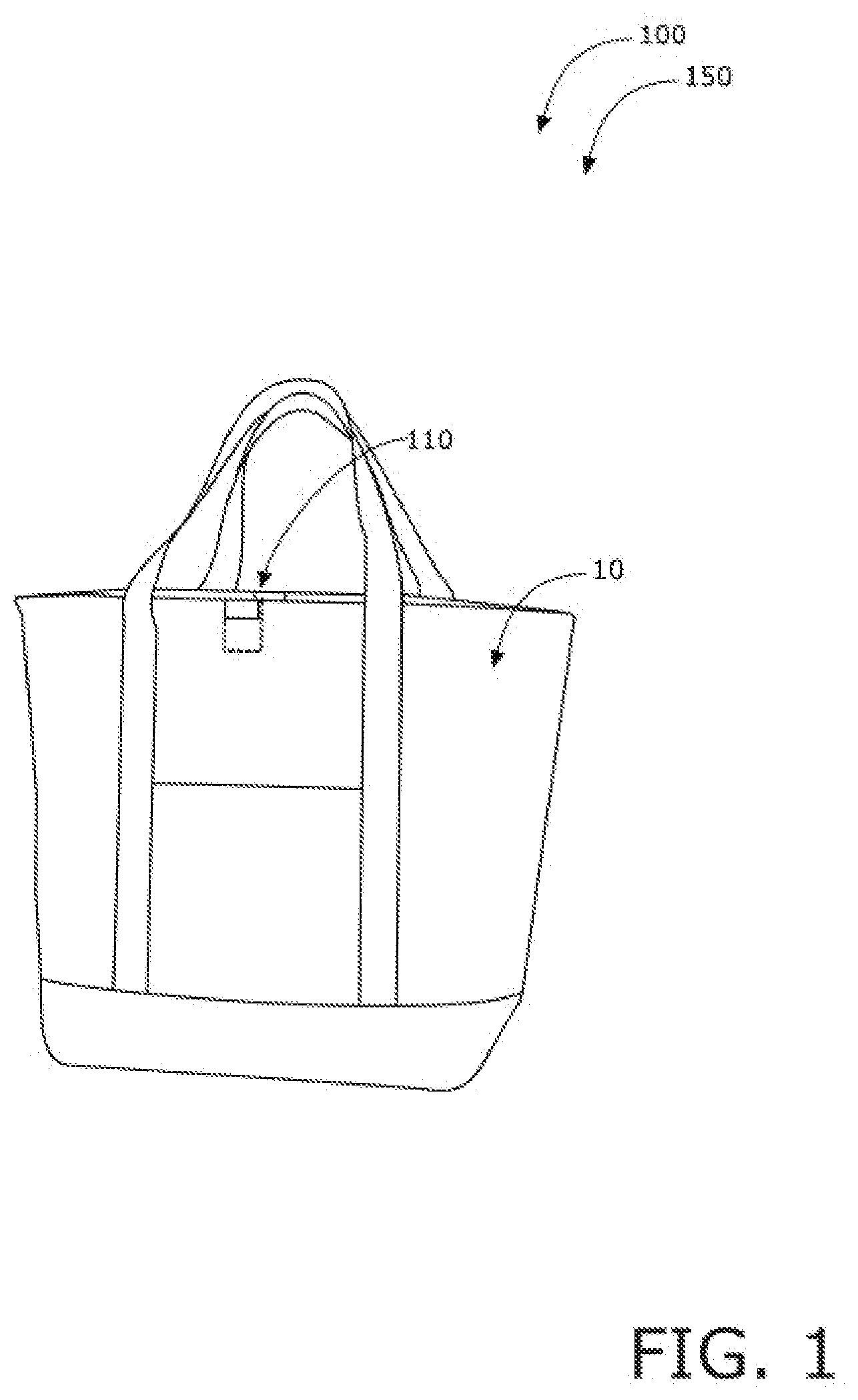
[0010] FIG. 1 is a perspective view of the purse security clip system during an `in-use` condition, according to an embodiment of the disclosure.
[0011] FIG. 2 is a perspective view of the purse security clip system of FIG. 1, according to an embodiment of the present disclosure.
[0012] FIG. 3 is a top view of the purse security clip system of FIG. 1, according to an embodiment of the present disclosure.
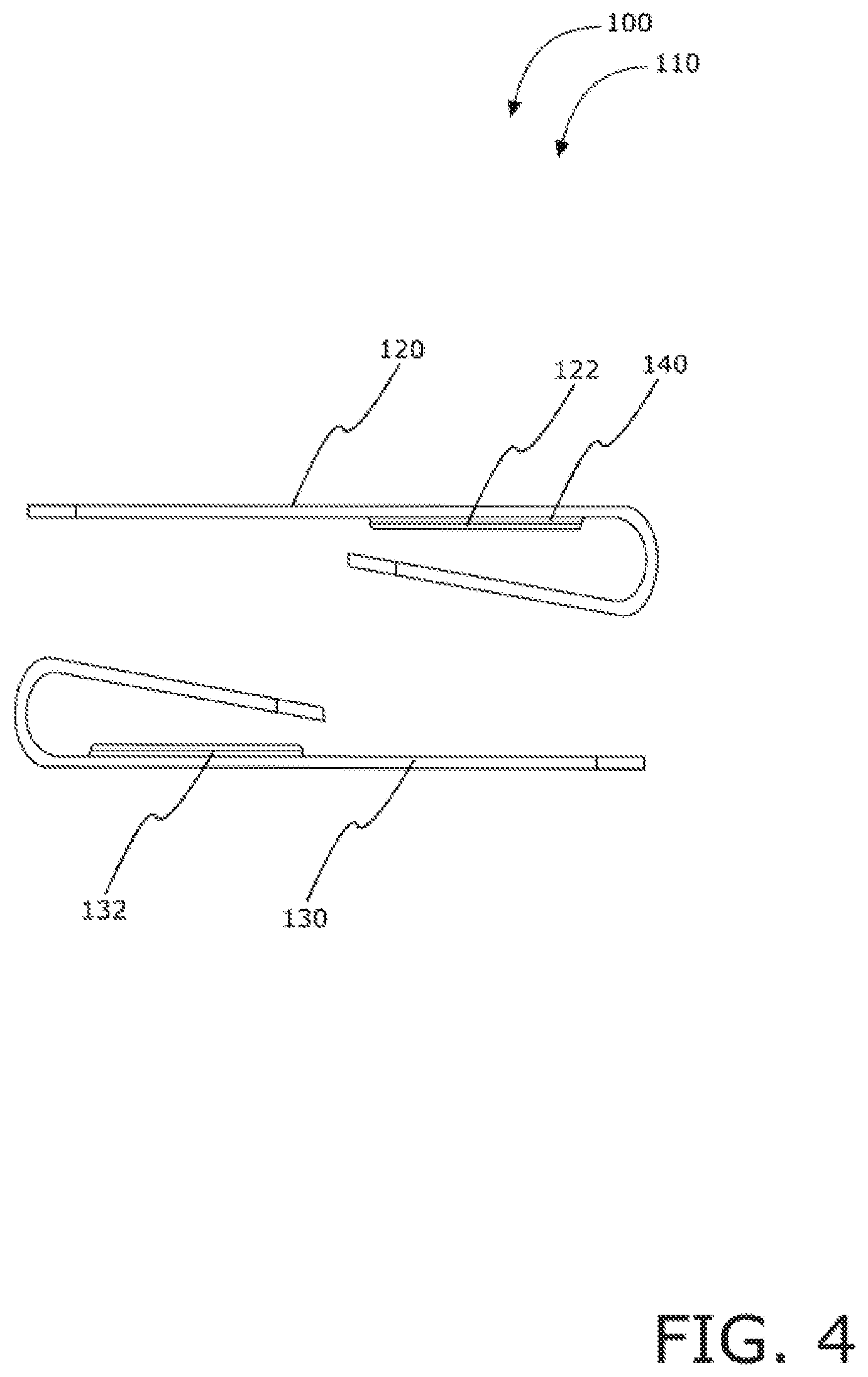
[0013] FIG. 4 is a side view of the purse security clip system of FIG. 1, according to an embodiment of the present disclosure.
[0014] FIG. 5 is a view of a kit of the purse security clip system of FIG. 1, according to an embodiment of the present disclosure.
[0015] The various embodiments of the present invention will hereinafter be described in conjunction with the appended drawings, wherein like designations denote like elements.
DETAILED DESCRIPTION
[0016] As discussed above, embodiments of the present disclosure relate to a handbags and purses and more particularly to a purse security clip system as used to improve the security of a handbag.
[0017] Generally, the invention is a set of magnetic clips used to secure contents inside a purse/handbag. The magnetic clips may be applied to a top open end of a bag opposing another one of the magnetic clips. When the magnetic clips are mated, a purse can be securely closed. A user may use 2-4 or 6 of the magnetic clips and add them to any purse to keep everything inside even if the purse being dropped, fallen over, etc. Any numbers of styles, colors, materials, logos etc., could be added to stylishly fit the look of any purse from designer label to a basic handbag.
[0018] Referring now more specifically to the drawings by numerals of reference, there is shown in FIGS. 1-5, various views of a purse security clip system 100. FIG. 1 shows a purse security clip system 100 during an `in-use` condition 150 according to an embodiment of the present disclosure. As illustrated, the purse security clip system 100 may include a securing assembly 110 having a first biasing clip member 120 and a second biasing clip member 130. The first biasing clip member 120 and the second biasing clip member 130 each comprise a fastener 140 configured on a back plate 144 of the first biasing clip member 120 and the second biasing clip member 130. The fastener 140 is configured to couple the first biasing clip member 120 to the second biasing clip member 130 when mated. The first biasing clip member 120 and the second biasing clip member 130 are configured to be secured to and positioned opposing one another along an open top end of a bag 10, and when mated. The securing assembly 110 secures an open top end of the bag 10 in a closed position preventing items from falling out. The device may be used on all types of handbags, purses, or other bags 10 with an open top end.
[0019] Referring now to FIG. 2 showing a perspective view of the purse security clip system 100 of FIG. 1, according to an embodiment of the present disclosure. As above, the purse security clip system 100 may include the securing assembly 110 including the first biasing clip member 120 and the second biasing clip member 130. The securing assembly 110 is configured to be retro-fitted to an existing bag 10. A first-fastener 122 is configured on the back plate 144 of the first biasing clip member 120. A second-fastener 132 is configured on the back plate 144 of the second biasing clip member 130. The first-fastener 122 and the second-fastener 132 are opposing one another during an in-use condition. The first-fastener 122 is configured to be mated to the second-fastener 132.
[0020] FIG. 3 shows a top view of the purse security clip system 100 of FIG. 1, according to an embodiment of the present disclosure. As above, the purse security clip system 100 may include the first biasing clip member 120 and the second biasing clip member 130 to be used in functional combination to further secure a bag 10 in a closed position. The first biasing clip member 120 and the second biasing clip member 130 each comprise a clamping means. The clamping means provides biasing means configured to clip on the open top end of the bag 10. The first biasing clip member 120 and the second biasing clip member 130 are semi-flexible and configured to allow the clamping means to extend to apply the first biasing clip member 120 and the second biasing clip member 130 to the open top end of the bag 10 and retract to bias the open top end of the bag 10.
[0021] Referring now to FIG. 4 showing a side view of the purse security clip system 100 of FIG. 1, according to an embodiment of the present disclosure. As above, the purse security clip system 100 may include the securing assembly 110 including the first biasing clip member 120 and the second biasing clip member 130. In a preferred embodiment the fastener 140 is a magnet, however, other suitable fasteners may be used. The first-fastener 122 and the second fastener 132 comprise opposite poles configured to attract to one another when in close proximity. The first biasing clip member 120 and the second biasing clip member 130 are configured to be used in pairs. A minimum of one of the first biasing clip member 120 and one of the second biasing clip member 130 is used to secure the open top end of the bag 10 in a closed position. A user may use as many pairs as needed.
[0022] The first-fastener 122 and the second fastener are removeable from each other and the first biasing clip member 120 and the second biasing clip member 130 are repositionable along the open top end of the bag 10. The backplates 144 of the first biasing clip member 120 and the second biasing clip member 130 are configured on an inside portion of a flexible wall of the bag 10 during an engaged position with the open top end of the bag 10. The flexible wall of the bag 10 are configured to move together and secure contents within, when the first biasing clip member 120 and the second biasing clip member 130 mate. The first biasing clip member 120 and the second biasing clip member 130 may further comprise functional indicia, designs, and colors.
[0023] Referring now to FIG. 5 showing a view of a kit of the purse security clip system 100 of FIG. 1, according to one embodiment, the purse security clip system 100 may be arranged as a kit. The kit may include at least one first biasing clip member 120, at least one second biasing clip member 130, and a set of instructions. The instructions may detail functional relationships in relation to the structure of the purse security clip system 100 (such that the purse security clip system 100 can be used, maintained, or the like, in a preferred manner).
[0024] The embodiments of the invention described herein are exemplary and numerous modifications, variations and rearrangements can be readily envisioned to achieve substantially equivalent results, all of which are intended to be embraced within the spirit and scope of the invention. Further, the purpose of the foregoing abstract is to enable the U.S. Patent and Trademark Office and the public generally, and especially the scientist, engineers and practitioners in the art who are not familiar with patent or legal terms or phraseology, to determine quickly from a cursory inspection the nature and essence of the technical disclosure of the application.
* * * * *
D00000
D00001
D00002
D00003
D00004
D00005
XML
uspto.report is an independent third-party trademark research tool that is not affiliated, endorsed, or sponsored by the United States Patent and Trademark Office (USPTO) or any other governmental organization. The information provided by uspto.report is based on publicly available data at the time of writing and is intended for informational purposes only.
While we strive to provide accurate and up-to-date information, we do not guarantee the accuracy, completeness, reliability, or suitability of the information displayed on this site. The use of this site is at your own risk. Any reliance you place on such information is therefore strictly at your own risk.
All official trademark data, including owner information, should be verified by visiting the official USPTO website at www.uspto.gov. This site is not intended to replace professional legal advice and should not be used as a substitute for consulting with a legal professional who is knowledgeable about trademark law.