Method And Apparatus For Providing Automatic Mirror Setting Via Inward Facing Cameras
Cordell; John Palmer ; et al.
U.S. patent application number 16/542242 was filed with the patent office on 2019-12-05 for method and apparatus for providing automatic mirror setting via inward facing cameras. This patent application is currently assigned to Xevo Inc.. The applicant listed for this patent is Xevo Inc.. Invention is credited to John Palmer Cordell, John Hayes Ludwig, Samuel James McKelvie, Robert Victor Welland.
| Application Number | 20190370581 16/542242 |
| Document ID | / |
| Family ID | 61159300 |
| Filed Date | 2019-12-05 |


View All Diagrams
| United States Patent Application | 20190370581 |
| Kind Code | A1 |
| Cordell; John Palmer ; et al. | December 5, 2019 |
METHOD AND APPARATUS FOR PROVIDING AUTOMATIC MIRROR SETTING VIA INWARD FACING CAMERAS
Abstract
A method or system that is able to adjust an exterior mirror of a vehicle via an automatic mirror-setting ("AM") model managed by a virtuous cycle containing a cloud based network ("CBN"). The system includes a set of mirrors, a set of inward facing cameras, a vehicle onboard computer ("VOC"), and AM module. In one embodiment, the mirrors, attached to a vehicle, are configured to capture at least a portion of the external environment in which the vehicle operates. The inward facing cameras, mounted in the vehicle, are configured to collect internal images, including the operator's facial features showing operator visual characteristics. The VOC, which is coupled to the CBN, is configured to determine operator vision metadata based on the internal images, operator visual characteristics, and historical stored data. The AM module is able to adaptively set a mirror to an optimal orientation so that the area of the external blind spot is minimized.
| Inventors: | Cordell; John Palmer; (Seattle, WA) ; Welland; Robert Victor; (Seattle, WA) ; McKelvie; Samuel James; (S. Seattle, WA) ; Ludwig; John Hayes; (Bellevue, WA) | ||||||||||
| Applicant: |
|
||||||||||
|---|---|---|---|---|---|---|---|---|---|---|---|
| Assignee: | Xevo Inc. Bellevue WA |
||||||||||
| Family ID: | 61159300 | ||||||||||
| Appl. No.: | 16/542242 | ||||||||||
| Filed: | August 15, 2019 |
Related U.S. Patent Documents
| Application Number | Filing Date | Patent Number | ||
|---|---|---|---|---|
| 15672897 | Aug 9, 2017 | |||
| 16542242 | ||||
| 62372999 | Aug 10, 2016 | |||
| Current U.S. Class: | 1/1 |
| Current CPC Class: | G06K 9/66 20130101; B60R 1/04 20130101; G06K 9/00812 20130101; H04N 7/188 20130101; B60R 1/00 20130101; G06K 9/00791 20130101; G01C 21/3602 20130101; G05D 1/0246 20130101; G08G 1/143 20130101; G08G 1/0129 20130101; G08G 1/0969 20130101; B60R 2300/8006 20130101; G06N 20/00 20190101; G01C 21/3605 20130101; B60R 1/062 20130101; G06F 3/013 20130101; H04W 4/02 20130101; G06K 2209/27 20130101; G06N 3/08 20130101; G08G 1/096888 20130101; H04L 67/10 20130101; H04W 4/44 20180201; G01S 19/48 20130101; G08G 1/0116 20130101; G06K 9/00604 20130101; G06K 9/00798 20130101; G08G 1/096861 20130101; G06K 9/00281 20130101; G06K 9/00832 20130101; G06K 9/00979 20130101; G08G 1/0112 20130101; G08G 1/04 20130101; B60Q 9/008 20130101; G05D 1/0214 20130101; G06K 9/00845 20130101; G06K 9/00805 20130101; G08G 1/166 20130101; G06N 3/0454 20130101; G08G 1/096811 20130101; B60R 2300/105 20130101 |
| International Class: | G06K 9/00 20060101 G06K009/00; B60Q 9/00 20060101 B60Q009/00; G06K 9/66 20060101 G06K009/66; G08G 1/16 20060101 G08G001/16; G08G 1/01 20060101 G08G001/01; G08G 1/04 20060101 G08G001/04; B60R 1/00 20060101 B60R001/00; B60R 1/04 20060101 B60R001/04; B60R 1/062 20060101 B60R001/062; G01C 21/36 20060101 G01C021/36; G01S 19/48 20060101 G01S019/48; G08G 1/0968 20060101 G08G001/0968; G08G 1/14 20060101 G08G001/14; H04N 7/18 20060101 H04N007/18 |
Claims
1. A computing device, comprising: a memory that is configured to store computer instructions; and one or more processors that are configured to execute the computer instructions to: receive at least one first image of an area external to a vehicle; receive at least one second image of a driver of the vehicle; analyze the at least one first image to detect movement of an object relative to the vehicle; detect an abnormal event based on the movement of the object; in response to the detected abnormal event, analyze the at least one second image to determine a head position of the driver within the vehicle and a gaze direction of the driver; determine an orientation of at least one mirror on the vehicle based on the movement of the object and the driver's head position and gaze direction relative to the at least one mirror; automatically adjust a position of the at least one mirror using the determined orientation to enable the driver to see the abnormal event via the at least one mirror; and provide further automatic adjustments of the position of the at least one mirror based on tracked changes in the movement of the object.
2. The computing device of claim 1, wherein the one or more processors are configured to receive the at least one second image of the driver of the vehicle by executing further computer instructions to: receive the at least one second image of the driver in response to the detected abnormal event.
3. The computing device of claim 1, wherein the one or more processors are configured to receive the at least one second image of the driver of the vehicle by executing further computer instructions to: receive the at least one second image of the driver prior to detection of the abnormal event.
4. The computing device of claim 1, wherein the one or more processors are configured to execute further computer instructions to: determine a projected location of the object based on the movement of the object; determine the orientation of the at least one mirror on the vehicle based on the projected location of the object and the driver's head position and gaze direction relative to the at least one mirror; and automatically adjust the position of the at least one mirror using the determined orientation to enable the driver to see the abnormal event via the at least one mirror at the projected location.
5. The computing device of claim 1, wherein the one or more processors are configured to provide the further automatic adjustments of the position of the at least one mirror by executing further computer instructions to: receive at least one third image of the area external to the vehicle; analyze the at least one third image to detect second movement of the object relative to the vehicle; receive at least one fourth image of the driver of the vehicle; analyze the at least one fourth image to determine a second head position of the driver within the vehicle and a second gaze direction of the driver; determine a second orientation of at least one mirror on the vehicle based on the second movement of the object and the driver's second head position and second gaze direction relative to the at least one mirror; and automatically adjust the position of the at least one mirror to a new position using the determined second orientation to enable the driver to maintain visual of the abnormal event via the at least one mirror.
6. The computing device of claim 1, wherein the one or more processors are configured to execute further computer instructions to: provide a notice to the driver indicating the abnormal event.
7. The computing device of claim 1, wherein the one or more processors are configured to execute further computer instructions to: provide a notice to the driver indicating the adjusted position of the at least one mirror in response to the abnormal event.
8. A method, comprising: obtaining a plurality of first images of an area external to a vehicle; obtaining a plurality of second images of a driver of the vehicle; determining first movement of an object relative to the vehicle based on an analysis of at least a first subset of the plurality of first images; detecting an abnormal event at a first location relative to the vehicle based on the movement of the object; when the detected abnormal event is detected, determining a first head position of the driver based on an analysis of a first subset of the plurality of second images; determining a first orientation of at least one mirror on the vehicle based on the first location of the abnormal event and the first head position of the driver relative to the at least one mirror; automatically repositioning the at least one mirror using the determined first orientation to enable the driver to see the abnormal event at the first location via the at least one mirror; determining a second location of the abnormal event relative to the vehicle based on an analysis of at least a second subset of the plurality of first images; determining a second head position of the driver within the vehicle based on an analysis of a second subset of the plurality of second images; determining a second orientation of the at least one mirror based on the second location of the abnormal event and the second head position of the driver relative to the at least one mirror; and automatically repositioning the at least one mirror using the determined second orientation to enable the driver to track the abnormal event from the first location to the second location via the at least one mirror.
9. The method of claim 8, wherein obtaining the plurality of second images of the driver of the vehicle includes: capturing the plurality of second images of the driver in response to the detected abnormal event.
10. The method of claim 8, wherein obtaining the plurality of second images of the driver of the vehicle includes: capturing the plurality of second images of the driver prior to detection of the abnormal event.
11. The method of claim 8, further comprising: determining a projected location of the object based on movement of the object from the first location to the second location; determining a third orientation of the at least one mirror based on the projected location of the object; and automatically repositioning the at least one mirror using the determined third orientation to enable the driver to see the abnormal event via the at least one mirror at the projected location.
12. The method of claim 8, further comprising: providing a notice to the driver indicating the abnormal event.
13. The method of claim 8, further comprising: providing a notice to the driver indicating the repositioning of the at least one mirror in response to the abnormal event.
14. A system comprising: at least one mirror attached to a vehicle; at least one first camera configured to capture a plurality of first images of an area external to the vehicle; at least one second camera configured to capture at least one second image of a driver of the vehicle; and a computing device, comprising: a memory that is configured to store computer instructions; and one or more processors that are configured to execute the computer instructions to: obtain, via the at least one first camera, the plurality of first images of the area external to the vehicle; analyze the plurality of first images to detect an abnormal event based on movement of an object relative to the vehicle; in response to the detected abnormal event: determine a projected location of the object relative to the vehicle based on the movement of the object; capture, via the at least one second camera, the at least one second image of the driver of the vehicle; analyze the at least one second image to determine a gaze direction of the driver; determine an orientation of the at least one mirror based on the projected location of the object and the driver's gaze direction; and automatically adjust a position of the at least one mirror using the determined orientation to enable the driver to see the abnormal event via the at least one mirror when the object reaches the projected location.
15. The system of claim 14, wherein the one or more processors are configured to execute further computer instructions to: track, based on images captured via the at least one first camera, movement of the object from the projected location to another location; determine, based on images captured via the at least one second camera, an updated gaze direction of the driver as the object is being tracked; and automatically adjust the position of the at least one mirror based on the tracked movement of the object and the updated driver's gaze direction to enable the driver to visually follow the abnormal event via the at least one mirror.
16. The system of claim 14, further comprising: an output device, wherein the one or more processors are configured to execute further computer instructions to: provide, via the output device, a notice to the driver indicating the abnormal event.
17. The system of claim 14, further comprising: an output device, wherein the one or more processors are configured to execute further computer instructions to: provide, via the output device, a notice to the driver indicating the adjusted position of the at least one mirror in response to the abnormal event.
Description
BACKGROUND
Technical Field
[0001] The exemplary embodiment(s) of the present invention relates to the field of communication networks. More specifically, the exemplary embodiment(s) of the present invention relates to operating an intelligent machine using a virtuous cycle between cloud, machine learning, and containerized sensors.
Description of the Related Art
[0002] With increasing popularity of automation and intelligent electronic devices, such as computerized machines, the Internet of Things ("IoT"), smart vehicles, smart phones, drones, mobile devices, airplanes, artificial intelligence ("AI"), the demand of intelligent machines and faster real-time response are increasing. To properly provide machine learning, a significant number of pieces, such as data management, model training, and data collection, needs to be improved.
[0003] A conventional type of machine learning is, in itself, an exploratory process, which may involve trying different kinds of models, such as convolutional, recurrent neural network ("RNN"), et cetera. Machine learning or training typically concerns a wide variety of hyper-parameters that change the shape of the model and training characteristics. Model training generally requires intensive computation. As such, real-time response via machine learning model can be challenging.
[0004] A drawback associated with a traditional automobile or vehicle is that most mirrors, especially external mirrors, on both sides of the vehicle are typically set incorrectly so the driver often times has a large or big blind spot on both sides of the vehicle. Typically, the driver's head position is different when setting the mirror than while driving the vehicle.
SUMMARY
[0005] One embodiment of the presently claimed invention discloses a method and/or system capable of adaptively adjusting one or more mirrors mounted on a vehicle via an automatic mirror-setting ("AM") model managed by a virtuous cycle containing a machine learning center ("MLC") and cloud based network ("CBN"). The system or AM system includes a set of mirrors, a set of inward facing cameras, a vehicle onboard computer ("VOC"), and an AM module. In one embodiment, the mirrors, attached to the vehicle, are configured to capture at least a portion of the external environment in which the vehicle operates. In one example, the mirrors include a left exterior side mirror, a right exterior side mirror, and an interior center mirror. The external environment includes a road, nearby structures, pedestrians, traffic conditions, nearby cars, and traffic lights.
[0006] The inward facing cameras, mounted inside of the vehicle, are configured to collect internal images including operator facial features showing operator visual characteristics. The VOC, which is coupled to the CBN, is configured to determine operator vision metadata based on the internal images, operator visual characteristics, and historical stored data. In one example, the inward facing cameras include multiple exteriorly mounted image sensors capable of capturing internal images relating to the position of driver relative to the driver's seat and interior of the vehicle. The operator visual characteristics include the number of eyes on the operator's facial features. Also, the operator visual characteristics include peripheral vision, vision boundary, and height of visual center.
[0007] The AM module is able to adaptively set a mirror to an optimal orientation so that the area of the external blind spot is minimized. The AM module includes at least a portion of an AM model, which is able to dynamically adjust the orientation of at least one of the plurality of mirrors to show an event associated with the external environment based on the external images and historical data from the CBN. In one embodiment, the AM model includes an abnormal tracking function, which is able to realign orientation of at least one of the plurality of mirror to continuously track an abnormal event in response to the external images and real-time cloud data submitted by other nearby vehicles. It should be noted that the AM model is trained by the MLC, which is coupled to the VOC. A function of the MLC is to train and improve the AM model based on the labeled data from the CBN.
[0008] In one aspect, the AM system further includes outward facing cameras mounted on the vehicle for collecting external images representing the surrounding environment in which the vehicle operates. The CBN is wirelessly coupled to the VOC and configured to correlate and generate labeled data associated with the AM data based on historical cloud data, internal images, and external images. The outward facing cameras are configured to capture real-time images as the vehicle moves across a geographical area.
[0009] In an alternative embodiment, the presently claimed invention discloses a method or process for interactively setting a mirror mounted on a vehicle via metadata extraction utilizing a virtuous cycle including sensors, MLC, and CBN. The process is capable of receiving a mirror resetting signal indicating at least one mirror mounted on a vehicle requires an adjustment. Upon activating at least a portion of inward facing cameras mounted in the vehicle for capturing internal images, including driver eye level with respect to interior of the vehicle and historical cloud data associated with the vehicle and driver, images are obtained from a virtuous cycle. The process subsequently adjusts at least one mirror to an orientation with a minimal blind spot in accordance with the driver's head position shown in the internal image and historical cloud data. In one aspect, the internal images are continuously obtained for a predefined wait period until the driver has settled down so that an accurate calculation of the driver's head position can be computed. It should be noted that the set of outward facing cameras mounted on the vehicle can be activated for recording external surrounding images representing a geographic environment in which the vehicle operates. In one aspect, the AM model is capable of tracking a surrounding environmental event in accordance with the external surrounding images and historical data supplied by the virtuous cycle.
[0010] In an alternative embodiment, the AM system is able to perform a process configured to utilizing one of external mirrors mounted on a vehicle to dynamically track an abnormal event facilitated via the virtuous cycle. After receiving a message of detecting an abnormal event in the nearby surrounding area in which the vehicle operates from cloud based data pushed by the MLC, images showing the driver's head position captured by a set of interior cameras are obtained while the driver operates the moving vehicle. The process is capable of adaptively adjusting orientation of at least one mirror to track the abnormal event based on projected location according to the message so that the driver is able to see the abnormal event. In one example, the AM model is able to issue a notice telling the driver to watch the abnormal event at the newly reoriented mirror. It should be noted that the labeled data representing driver reaction responding to the abnormal event is uploaded back to the CBN for facilitating AM model training at the MLC.
[0011] Additional features and benefits of the exemplary embodiment(s) of the present invention will become apparent from the detailed description, figures and claims set forth below.
BRIEF DESCRIPTION OF THE DRAWINGS
[0012] The exemplary embodiment(s) of the present invention will be understood more fully from the detailed description given below and from the accompanying drawings of various embodiments of the invention which, however, should not be taken to limit the invention to the specific embodiments, but are for explanation and understanding only.
[0013] FIGS. 1A-1B show block diagrams illustrating a virtuous cycle facilitating an automatic mirror-setting ("AM") system capable of adaptively adjusting mirror(s) via a virtuous cycle in accordance with one embodiment of the present invention;
[0014] FIGS. 1C-1E show diagrams illustrating an AM model providing mirror adjustment using inward and/or outward facing cameras via a virtuous cycle in accordance with one embodiment of the present invention;
[0015] FIGS. 1F-1H show a block diagram illustrating a pipeline process of an outward facing camera capable of identifying and classifying detected object(s) using a virtuous cycle in accordance with one embodiment of the present invention;
[0016] FIGS. 2A-2B show block diagrams illustrating a virtuous cycle capable of facilitating an AM model detection in accordance with one embodiment of the present invention;
[0017] FIG. 3 shows a block diagram illustrating a cloud based network using crowdsourcing approach to improve AM model(s) in accordance with one embodiment of the present invention;
[0018] FIG. 4 shows a block diagram illustrating an AM model or system using the virtuous cycle in accordance with one embodiment of the present invention;
[0019] FIG. 5 shows a block diagram illustrating an exemplary process of correlating AM data in accordance with one embodiment of the present invention;
[0020] FIG. 6 shows a block diagram illustrating an exemplary process of real-time data management for AM model in accordance with one embodiment of the present invention;
[0021] FIG. 7 shows a block diagram illustrating a crowd sourced application model for an AM model in accordance with one embodiment of the present invention;
[0022] FIG. 8 shows a block diagram illustrating a method of storing AM related data using a geo-spatial objective storage in accordance with one embodiment of the present invention;
[0023] FIG. 9 shows a block diagram illustrating an exemplary approach of an analysis engine analyzing AM data in accordance with one embodiment of the present invention;
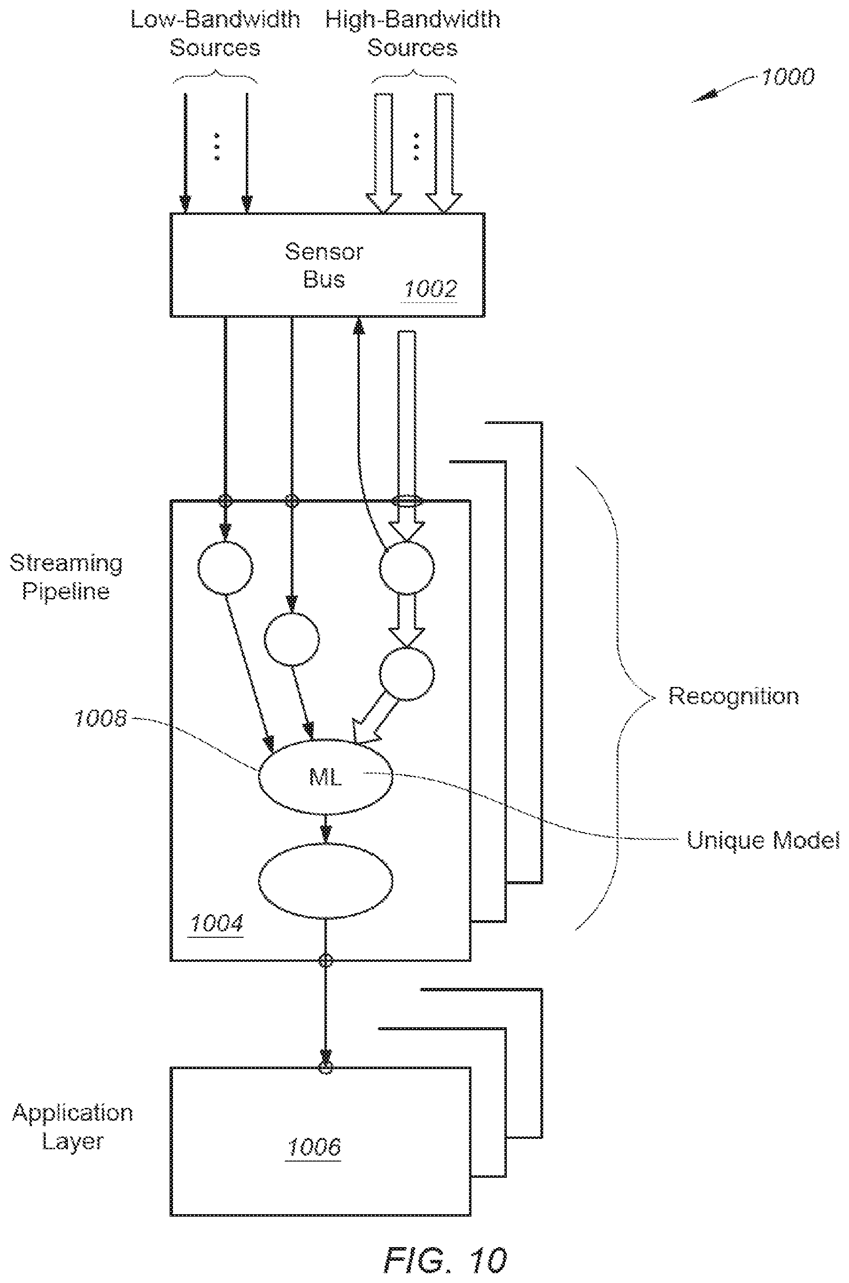
[0024] FIG. 10 shows a block diagram illustrating an exemplary containerized sensor network used for sensing AM related information in accordance with one embodiment of the present invention;
[0025] FIG. 11 shows a block diagram illustrating a processing device or computer system that can be installed in a vehicle for facilitating the virtuous cycle in accordance with one embodiment of the present invention; and
[0026] FIG. 12 shows a flowchart illustrating a process of an AM model or system capable of providing a driver rating in accordance with one embodiment of the present invention.
DETAILED DESCRIPTION
[0027] Embodiments of the present invention are described herein with context of a method and/or apparatus for facilitating automatic mirror adjustment based on images captured by inward facing cameras via an AM model continuously trained by a virtuous cycle containing a cloud based network, a containerized sensing device, and a machine learning center ("MLC").
[0028] The purpose of the following detailed description is to provide an understanding of one or more embodiments of the present invention. Those of ordinary skills in the art will realize that the following detailed description is illustrative only and is not intended to be in any way limiting. Other embodiments will readily suggest themselves to such skilled persons having the benefit of this disclosure and/or description.
[0029] In the interest of clarity, not all of the routine features of the implementations described herein are shown and described. It will, of course, be understood that in the development of any such actual implementation, numerous implementation-specific decisions may be made in order to achieve the developer's specific goals, such as compliance with application- and business-related constraints, and that these specific goals will vary from one implementation to another and from one developer to another. Moreover, it will be understood that such a development effort might be complex and time-consuming, but would nevertheless be a routine undertaking of engineering for those of ordinary skills in the art having the benefit of embodiments of this disclosure.
[0030] Various embodiments of the present invention illustrated in the drawings may not be drawn to scale. Rather, the dimensions of the various features may be expanded or reduced for clarity. In addition, some of the drawings may be simplified for clarity. Thus, the drawings may not depict all of the components of a given apparatus (e.g., device) or method. The same reference indicators will be used throughout the drawings and the following detailed description to refer to the same or like parts.
[0031] In accordance with embodiments of present invention, the components, process steps, and/or data structures described herein may be implemented using various types of operating systems, computing platforms, computer programs, and/or general purpose machines. In addition, those of ordinary skills in the art will recognize that devices of a less general purpose nature, such as hardware devices, field programmable gate arrays (FPGAs), application specific integrated circuits (ASICs), or the like, may also be used without departing from the scope and spirit of the inventive concepts disclosed herein. Where a method comprising a series of process steps is implemented by a computer or a machine and those process steps can be stored as a series of instructions readable by the machine, they may be stored on a tangible medium such as a computer memory device (e.g., Read Only Memory ("ROM"), Programmable Read Only Memory ("PROM"), Electrically Erasable Programmable Read Only Memory ("EEPROM"), FLASH Memory, Jump Drive, and the like), magnetic storage medium (e.g., tape, magnetic disk drive, and the like), optical storage medium (e.g., CD-ROM, DVD-ROM, paper card and paper tape, and the like) and other known types of program memory.
[0032] The term "system" or "device" is used generically herein to describe any number of components, elements, sub-systems, devices, packet switch elements, packet switches, access switches, routers, networks, computer and/or communication devices or mechanisms, or combinations of components thereof. The term "computer" includes a processor, memory, and buses capable of executing instruction wherein the computer refers to one or a cluster of computers, personal computers, workstations, mainframes, or combinations of computers thereof.
[0033] One embodiment of the presently claimed invention discloses a method or system capable of adjusting an exterior mirror of a vehicle via an automatic mirror-setting ("AM") model managed by a virtuous cycle containing a machine learning center ("MLC") and a cloud based network ("CBN"). The system or AM system includes a set of mirrors, a set of inward facing cameras, a vehicle onboard computer ("VOC"), and an AM module. In one embodiment, the mirrors, attached to a vehicle, are configured to capture at least a portion of the external environment in which the vehicle operates. The inward facing cameras, mounted in the vehicle, are configured to collect internal images including an operator's facial features showing operator visual characteristics. The VOC, which is coupled to the CBN, is configured to determine operator vision metadata based on the internal images, operator visual characteristics, and historical stored data. The AM module is able to adaptively set a mirror to an optimal orientation so that area of an external blind spot is minimized.
[0034] In an alternative embodiment, the AM system is able to perform a process configured to utilize one of the external mirrors mounted on a vehicle to dynamically track an abnormal event, facilitated via the virtuous cycle. After receiving a message of detecting an abnormal event in the nearby surrounding area in which the vehicle operates from cloud based data pushed by the MLC, images showing the driver's head position captured by a set of interior cameras is obtained while the driver operates moving vehicle. The process is capable of adaptively adjusting orientation of at least one mirror to track the abnormal event based on a projected location according to the message so that the driver is able to see the abnormal event. In one example, the AM model is able to issue a notice telling the driver to watch the abnormal event at the newly reoriented mirror. It should be noted that the labeled data representing the driver's reaction in responding to the abnormal event is uploaded back to the CBN for facilitating AM model training at the MLC.
[0035] FIG. 1A is a block diagram 100 illustrating a virtuous cycle facilitating an automatic mirror-setting ("AM") system capable of adaptively adjusting mirror(s) via a virtuous cycle in accordance with one embodiment of the present invention. Diagram 100 illustrates a virtuous cycle containing a vehicle 102, CBN 104, and MLC 106. In one aspect, MLC 106 can be located remotely or in the cloud. Alternatively, MLC 106 can be a part of CBN 104. It should be noted that the underlying concept of the exemplary embodiment(s) of the present invention would not change if one or more blocks (circuit or elements) were added to or removed from diagram 100.
[0036] Vehicle 102, in one example, can be a car, automobile, bus, train, drone, airplane, truck, and the like, and is capable of moving geographically from point A to point B. To simplify the forgoing discussing, the term "vehicle" or "car" is used. Vehicle 102 includes wheels with an ABS (anti-lock braking system), body, steering wheel 108, exterior or outward facing cameras 125, interior (or 360.degree. (degree)) or inward facing camera 126, antenna 124, onboard controller or VOC 123, and operator (or driver) 109. It should be noted that outward facing cameras 125 and/or inward facing cameras 126 can be installed at the front, side-facing, in stereo, and inside of vehicle 102. In one example, vehicle 102 also includes various sensors which sense information related to vehicle state, vehicle status, and driver actions. For example, the sensors, not shown in FIG. 1A, are able to collect information such as audio, ABS, steering, braking, acceleration, traction control, windshield wipers, global positioning system ("GPS"), radar, ultrasound, Light Detection and Ranging ("LiDAR"), and the like.
[0037] The VOC or onboard controller 123 includes a central processing unit ("CPU"), graphic processing unit ("GPU"), memory, and disk responsible for gathering data from outward facing or exterior cameras 125, inward facing or interior cameras 126, audio sensor, ABS, traction control, steering wheel, CAN-bus sensors, and the like. In one aspect, VOC 123 executes the AM model received from MLC 106, and interfaces with antenna 124 to communicate with CBN 104 via a wireless communication network 110. Note that the wireless communication network includes, but is not limited to, WIFI, cellular network, Bluetooth network, satellite network, or the like. A function of VOC 123 is to gather or capture real-time surrounding information as well as exterior information when vehicle 102 is moving.
[0038] CBN 104 includes various digital computing systems, such as, but not limited to, server farm 120, routers/switches 121, cloud administrators 119, connected computing devices 116, 117, and network elements 118. A function of CBN 104 is to provide cloud computing which can be viewed as on-demand Internet based computing service with enormous computing power and resources. Another function of CBN 104 is to improve or refine AM labeled data via correlating captured real-time data with relevant cloud data. The refined AM labeled data is subsequently passed to MLC 106 for model training via a connection 112.
[0039] MLC 106, in one embodiment, provides, refines, trains, and/or distributes models 115, such as the AM model, based on information or data, such as AM labeled data, provided from CBN 104. It should be noted that the machine learning makes the AM model based on models generated and maintained by various computational algorithms using historical data as well as current data. A function of MLC 106 is that it is capable of pushing information, such as the revised AM model, to vehicle 102 via a wireless communications network 114 in real-time.
[0040] To identify or collect current operator driving style via vehicle 102, an onboard AM model, which could reside inside of VOC 123 receives a triggering event or events from built-in sensors such as driver body language, external surrounding condition, internal detected images, ABS, wheel slip, turning status, engine status, and the like. The triggering event or events may include, but are not limited to, activation of ABS, texting, drinking, smoking, arguing, playing, fighting, rapid steering, rapid breaking, excessive wheel slip, activation of emergency stop, and so on. Upon receiving triggering events via vehicular status signals, the recording or recorded images captured by the inward facing camera or 360 camera are rewound from an earlier time stamp leading to the receipt of triggering event(s) for identifying, for example, AM labeled data which contains images of the driver's head position or abnormal events. After correlation of labeled data with historical sampling data at the CBN, the AM model is retrained and refined at MLC 106. The retrained AM model is subsequently pushed back onto vehicle 102.
[0041] It should be noted that by detecting the position of the driver's head, the system can automatically set the mirrors to the safest possible position. For example, by keeping track of the full range of positions the driver's head has been in, the system can determine the "center point" of their normal driving position. Note that the head position is usually different slightly from where they might place their head when performing a mirror adjustment. In one aspect, the AM model has a delay element where, during operation, upon pressing the button for "auto mirror set," a delay and a tone are issued to allow the driver to position themselves as they will be when driving.
[0042] During operation, inward facing camera 126 captures facial images of driver or operator 109, including the driver's head position and eye level. Upon verifying with CBN 104, a focal direction 107 of operator 109 is identified. After obtaining and processing external images relating to focal direction 107, a possible trajectory 105, in which the location is looked at, is obtained. Trajectory 105 and focal direction 107 are subsequently processed and combined in accordance with stored data in the cloud. The object, which is being looked at by operator 109, is identified. In this example, the object is a house 103 near the road. After identifying the driver's vision scope and trajectory, the eye level is determined wherein the eye level or head position will be used to adjust the mirrors to optimal orientations with minimal blind spots.
[0043] An advantage of using AM system is to reduce blind spots whereby traffic accidents should be reduced.
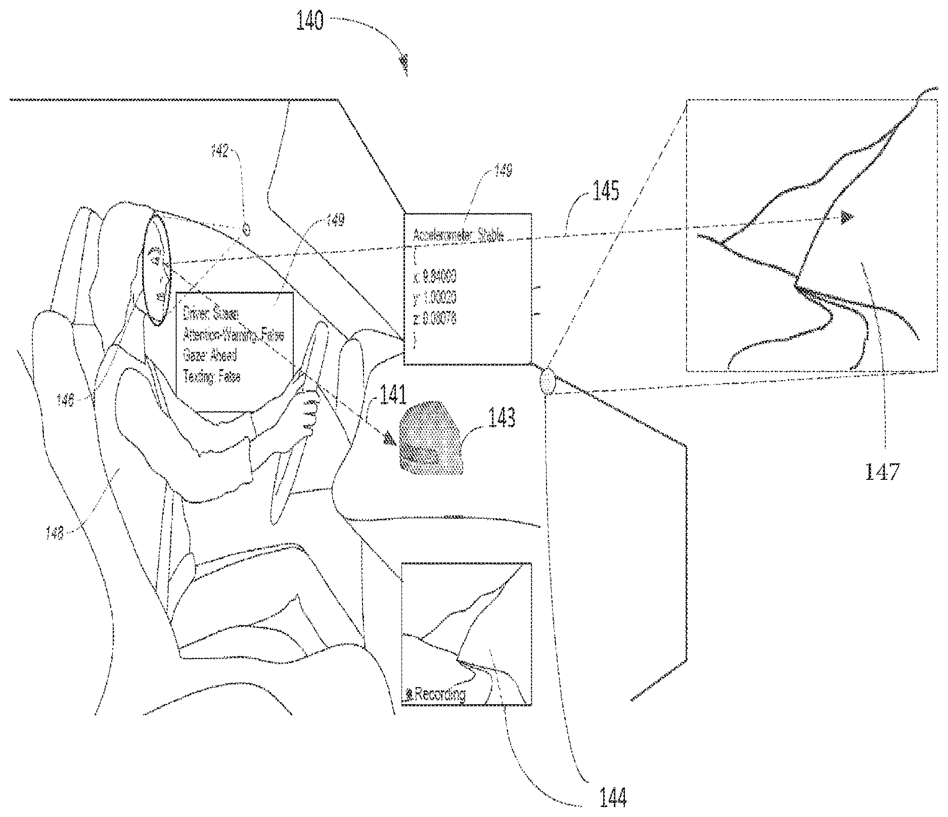
[0044] FIG. 1B illustrates a block diagram 140 showing an operator or driver monitored by an AM system for adaptively adjusting mirrors via a virtuous cycle in accordance with one embodiment of the present invention. Diagram 140 illustrates a driver 148, inward facing camera(s) 142, right external side mirror 143, and exterior camera 144. In one aspect, camera 142, also known as interior camera or 360 camera, monitors or captures the driver's facial expression 146 and/or the driver's (or operator's) body language, such as head position. Upon reading status 149, which indicates stable with accelerometer, ahead with gaze, hands on steering wheel (no texting), the AM model can conclude that driver is behaving normally or abnormally.
[0045] During an operation, the interior images captured by inward facing camera(s) 142 can show a location in which operator 148 is focusing based on the relative eye positions of operator 148. Once the direction of location such as direction 145 is identified, the AM system obtains external images captured by outward facing camera(s) 144. After identifying that image 147 is where the operator is paying attention based on direction 145, the image 147 is recorded and process. Based on detected trajectory 145, the AM model is able to identify the driver's vision associated with side mirrors. For example, the AM model can identify the optimal orientation for mirror 143 in view of driver vision 141 with minimum blind spots.
[0046] FIG. 1C illustrates diagrams 180 and 198 showing an AM model containing inward facing cameras to automatically set mirrors using a virtuous cycle in accordance with one embodiment of the present invention. Diagram 180, in one embodiment, includes interior car 189, exterior car 187, steering wheel 181, dashboard 182, driver head position 184, inward facing camera 190, and left mirror 188. With assistance of the virtuous cycle, the onboard vehicle computer can calculate driver head position 184 based on the observed images captured by inward facing camera 190. After calculation of driver head position 184 and his peripheral vision, left mirror 188 is automatically adjusted to view rear view 186 with the coverage providing a minimum blind spot as indicated by numeral 183. It should be noted that the underlying concept of the exemplary embodiment(s) of the present invention would not change if one or more blocks (components or elements) were added to or removed from diagram 180.
[0047] Diagram 180 illustrates a heuristic surrounding using a stream of head position data to choose the center point of eyes. In one embodiment, the AM system employs one or more internal cameras to extract metadata regarding the head position of a driver, and use that known position in space in order to automatically set the rearview mirrors to the optimal position for that driver. The AM model is, in one aspect, capable of calculating the optimal setting for rear mirrors based on obtained driver head position. For example, when drivers are sitting in their normal driving positions, their head may not stay in one place; instead they sweep through a range of space. The system is able to use extracted metadata about head position and, more importantly, the exact position of the driver's eyes. By combining information about the exact distance from the eyes to the rear mirrors, a vertical and horizontal angle can be calculated that will allow the driver to see what is happening behind them, while minimizing the size of the "blind spot" that can occur.
[0048] To operate functions of the AM model, vehicle geometry metrics may be used. For example, left mirror 188 has a metric of horizontal distance to the center of steering wheel and vertical distance to the center of steering wheel. The metrics also define mirror width, length, and height. An advantage of employing the AM model is that it is able to dynamically adjust external and/or internal mirrors to minimize blind spot(s).
[0049] Diagram 198 shows a heuristic illustration used for a filtered and weighted average of the driver's eye position. After capturing the inward facing camera output at block 191, the face and eye position is detected at block 192. Upon generation of a time series of extracted position of eyes at block 193, filter outlier data points are generated and/or extracted at block 194. At block 195, the weighted average of the eye position over a predefined time interval (t1, t2) is calculated and/or obtained.
[0050] FIG. 1D shows diagrams 1600, 1602 illustrating real-time coverage of a rear view mirror using an AM model via a virtuous cycle in accordance with one embodiment of the present invention. Diagram 1600 includes vehicle 1606, blind cars 1610, and visible cars 1612 wherein the rear view mirrors of vehicle 1606 are set improperly and whereby left side viewing coverage 1614 and right side viewing coverage 1618 miss blind cars 1610. Although coverages 1614, 1616, and 1618 cover visible cars 1612, blind cards 1610 are in blind spots. Diagram 1602 illustrates a scenario in which the rear view mirror of vehicle 1606 is set properly whereby blind cars 1610 are visible by new coverage 1624-1628. In one example, vehicle 1606 displays real-time coverage of the rear view mirror that all cars 1610, 1612 are observed leaving minimum blind spots.
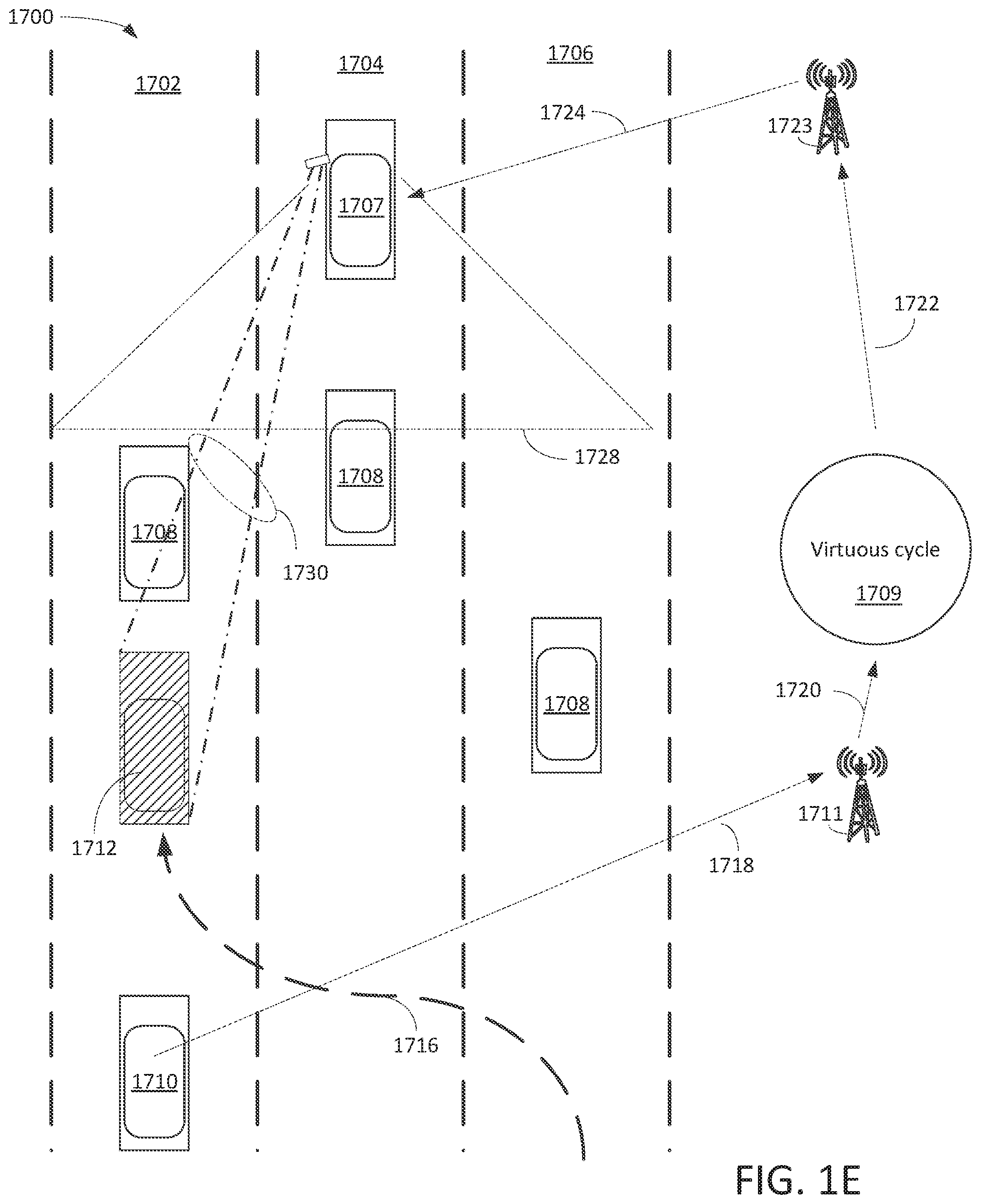
[0051] FIG. 1E is a block diagram 1700 illustrating a dynamic tracking function of an AM model containing inward and outward facing cameras via a virtuous cycle in accordance with one embodiment of the present invention. Diagram 1700 includes three lanes 1702, 1704, 1706, vehicle 1707, cars 1708, 1710, 1712, wireless transmission towers 1711, 1723, and virtuous cycle 1709. In one example, car 1712 is acting or driving recklessly which constitutes an abnormal event. It should be noted that the underlying concept of the exemplary embodiment(s) of the present invention would not change if one or more cars (components or elements) were added to or removed from diagram 1700.
[0052] In one embodiment, the AM model is able to notify the driver of an abnormal event nearby and direct the driver to monitor the situation via one or more mirrors, which is dynamic tracking an abnormal event, facilitated by the virtuous cycle 1709. In one aspect, the dynamic tracking function is able to move or turn mirror(s) to track the movement caused by the abnormal event. For example, when car 1712 is detected by car 1710 for speeding and changing multiple lanes at once as indicated by numeral 1716, car 1710 reports the reckless driving behavior as an abnormal event via wireless signals 1718 and 1720 to virtuous cycle 1709 via wireless tower 1711. After determining the abnormal event based on cloud data, virtuous cycle 1709 pushes the abnormal event to vehicle 1707 via wireless signals and connection 1722, 1724. The left external side mirror is automatically adjusted from original coverage 1728 to situational coverage 1730, which will track the movement of car 1712. The tracking will allow the driver to monitor the abnormal situation more effectively.
[0053] An advantage of using a dynamic tracking function of the AM model is that it provides an additional vision to the driver via mirror operation or adjustment.
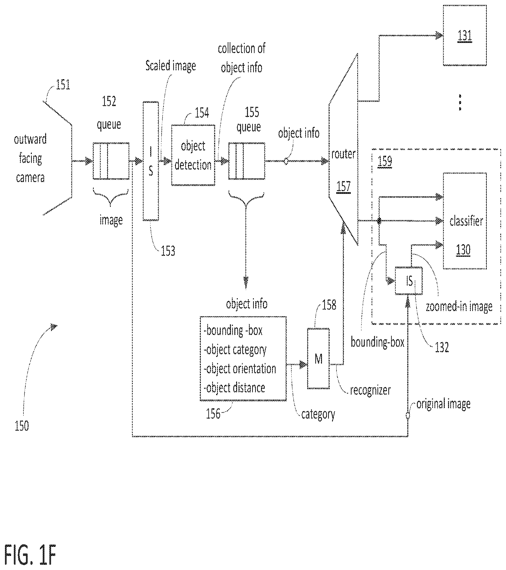
[0054] FIG. 1F is a logic block diagram illustrating a pipeline process 150 of an outward facing camera capable of identifying and classifying detected object(s) using a virtuous cycle in accordance with one embodiment of the present invention. Outward facing camera 151 collects images and the images are stored in a queue 152. After scaling the images by image scaling component 153, the scaled image is forwarded to object detection 154. Object detection 154 generates a collection of object information, which is forwarded to queue 155. The object information, which includes a bounding-box, an object category, an object orientation, and an object distance is forwarded to component 156 and router 157. Upon categorizing the object information at block 156, the categorized data is forwarded to map 158. After recognizing the object based on map 158, the information is forwarded to router 157. After routing information at router 157, the output images are forwarded to block 159, which uses classifier 130, 131 and image scaling component 132 to classify the images and/or objects.
[0055] Pipeline process 150 illustrates a logic processing flow, which is instantiated for the purpose of processing incoming data, extracting metadata on a frame by frame or data packet basis, and forwarding both frames and metadata packets forward through the pipeline. Each stage of the pipeline can contain software elements that perform operations upon the current audio, video, or sensor data frame. The elements in the pipeline can be inserted or removed while the pipeline is running, which allows for an adaptive pipeline that can perform different operations depending on the applications. The pipeline process is configured to adapt various system constraints that can be situationally present. Additionally, elements in the pipeline can have their internal settings updated in real-time, providing the ability to "turn off" or "turn on" elements, or to adjust their configuration settings on the fly.
[0056] Pipeline process 150 includes a metadata packet schema, which includes name/value pairs with arbitrary nesting and basic primitive data types such as arrays and structures that is used to create a self-describing, machine- and human-readable form of the extracted real-time metadata flowing through the system. Such a generalized schema allows multiple software components to agree on how to describe the high level events that are being captured, analyzed, and acted upon by the system. For example, a schema is constructed to describe the individual locations within a video frame of a person's eyes, nose, mouth, chin line, etc. Such a data structure allows a downstream software component to infer even higher level events, such as "this person is looking up at 34 degrees above the horizon" or "this person is looking left 18 degrees left of center." The process can subsequently construct additional metadata packets and insert them into the stream, resulting in higher level semantic metadata that the system is able to act upon.
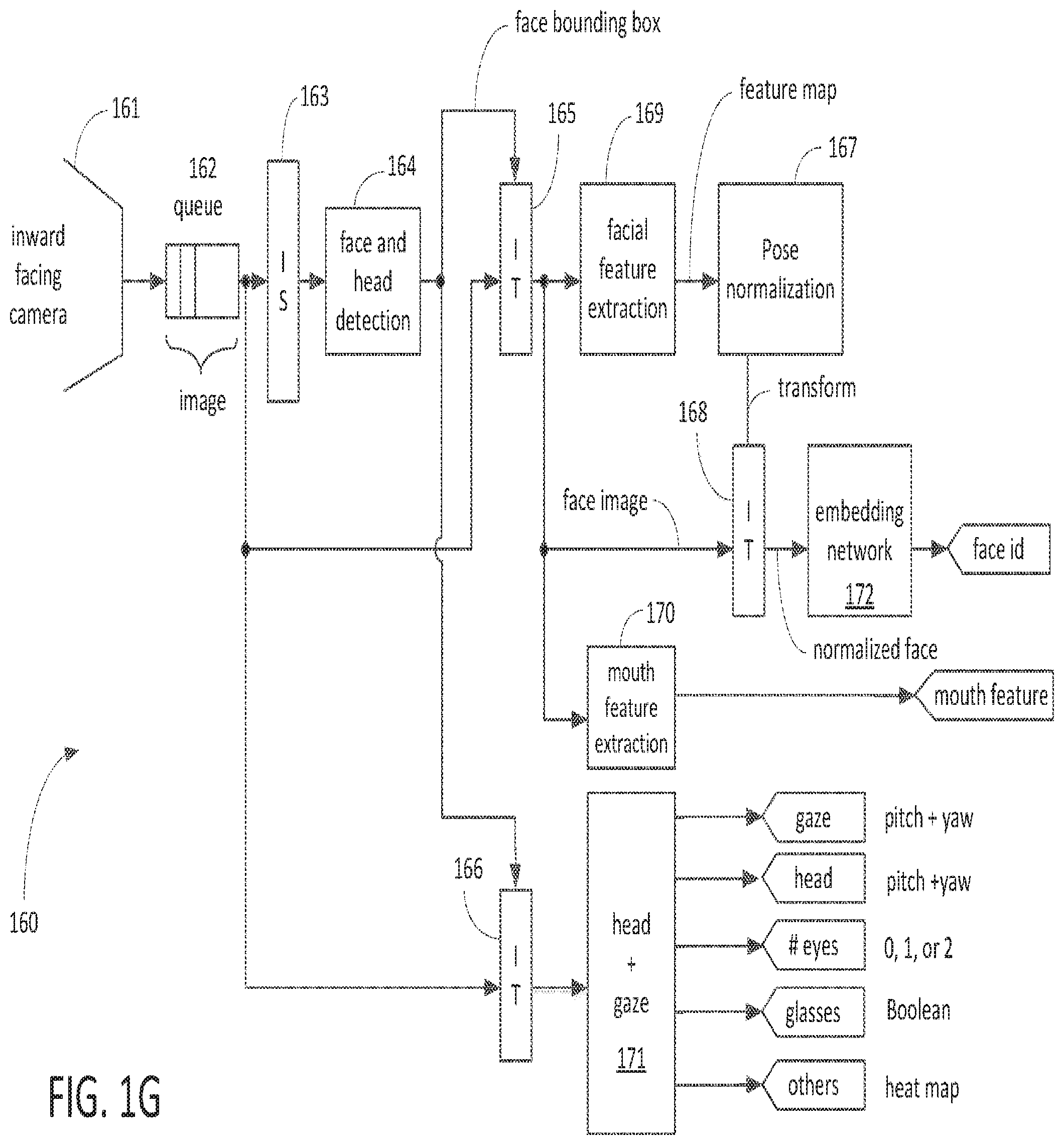
[0057] FIG. 1G is a logic block diagram illustrating a pipeline process 160 capable of identifying and classifying face detection, head and gaze orientation, and mouth features using a virtuous cycle in accordance with one embodiment of the present invention. Inward facing camera 161 collects images and the images are stored in a queue 162. After scaling the images by image scaling component 163, the scaled image is forwarded to face and head detection 164. The output of detection 164 is forwarded to image transform ("IT") components 165, 166. After transformation, the transformed image is forwarded to blocks 169, 170. After facial feature extraction in block 169, the feature map is forwarded to block 167 for pose normalization. Block 168 receives face images from IT component 165 and transformed images from block 167; the normalized face image is forwarded to block 172. Upon processing the normalized face with the embedding network at block 172, a face ID is identified.
[0058] Block 170 extracts the mouth feature and generates the mouth feature(s) of the driver. Block 171 processes head and gaze information based on output of IT component 166, which receives information with both scaled and unscaled images. In one example, block 171 is capable of generating various features, such as gaze, head, number of eyes, glasses, and the like.
[0059] FIG. 1H is a logic block diagram 175 illustrating a process of classifying detected object(s) using a virtuous cycle in accordance with one embodiment of the present invention. Block 176 is a software element used to classify a pedestrian based on collected external images captured by the outward facing cameras. Based on collected data and historical data, a pedestrian may be identified. Block 177 is a software element used to classify a vehicle based on collected external images captured by outward facing cameras. Based on collected data and historical data, the vehicle information can be identified. The exemplary classification information includes a model of the vehicle, a license plate, a state of vehicle registration, and the like. In addition, formation such as turn-signals, brake lights, and headlights can also be classified via facilitation of virtuous cycle. Block 178 is a software element used to classify traffic signals or conditions according to collected external images captured by the outward facing cameras. For example, according to collected data as well as historical data, the traffic signal can be classified. The exemplary classification includes a sign, a speed limit, a stop sign, and the like.
[0060] FIG. 2A is a block diagram 200 illustrating a virtuous cycle capable of detecting or monitoring an AM system in accordance with one embodiment of the present invention. Diagram 200, which is similar to diagram 100 shown in FIG. 1A, includes a containerized sensor network 206, real-world scale data 202, and continuous machine learning 204. In one embodiment, continuous machine learning 204 pushes real-time models to containerized sensor network 206 as indicated by numeral 210. Containerized sensor network 206 continuously feeds captured data or images to real-world scale data 202 with uploading in real-time or in a batched format as indicated by numeral 208. Real-world scale data 202 provides labeled data to continuous machine learning 204 for constant model training as indicated by numeral 212. It should be noted that the underlying concept of the exemplary embodiment(s) of the present invention would not change if one or more blocks (or elements) were added to or removed from FIG. 2A.
[0061] The virtuous cycle illustrated in diagram 200, in one embodiment, is configured to implement the AM system wherein containerized sensor network 206 is similar to vehicle 102 as shown in FIG. 1A and real-world scale data 202 is similar to CBN 104 shown in FIG. 1A. Also, continuous machine learning 204 is similar to MLC 106 shown in FIG. 1A. In one aspect, containerized sensor network 206, such as an automobile or car, contains a containerized sensing device capable of collecting surrounding information or images using onboard sensors or sensor network when the car is in motion. Based on the AM model, the collected surrounding information is selectively recorded to a local storage or memory.
[0062] Real-world scale data 202, such as the cloud or CBN, which is wirelessly coupled to the containerized sensing device, is able to correlate with cloud data and recently obtained AM data for producing labeled data. For example, real-world scale data 202 generates AM labeled data based on historical AM cloud data and the surrounding information sent from the containerized sensing device.
[0063] Continuous machine learning 204, such as the MLC or cloud, is configured to train and improve the AM model based on the labeled data from real-world scale data 202. With continuous gathering data and training AM model(s), the AM system will be able to learn, obtain, and/or collect all available data for the population samples.
[0064] In one embodiment, a virtuous cycle includes partition-able Machine Learning networks, training partitioned networks, partitioning a network using sub-modules, and composing partitioned networks. For example, a virtuous cycle involves data gathering from a device, creating intelligent behaviors from the data, and deploying the intelligence. In one example, partition idea includes knowing the age of a driver which could place or partition "dangerous driving" into multiple models and be selectively deployed by an "age detector." An advantage of using such partitioned models is that models should be able to perform a better job of recognition with the same resources because the domain of discourse is now smaller. Note that, even if some behaviors overlap by age, the partitioned models can have common recognition components.
[0065] It should be noted that with more context information collected, a better job of recognition can be generated. For example, "dangerous driving" can be further partitioned by weather condition, time of day, traffic conditions, et cetera. In the "dangerous driving" scenario, categories of dangerous driving can be partitioned into "inattention," "aggressive driving," "following too closely," "swerving," "driving too slowly," "frequent breaking," deceleration, ABS event, et cetera.
[0066] For example, by resisting a steering behavior that is erratic, the car gives the driver direct feedback on their behavior--if the resistance is modest enough then if the steering behavior is intentional (such as trying to avoid running over a small animal) then the driver is still able to perform their irregular action. However, if the driver is texting or inebriated then the correction may alert them to their behavior and get their attention. Similarly, someone engaged in "road rage" who is driving too close to another car may feel resistance on the gas pedal. A benefit of using the AM system is to identify driver head position and adjust mirror(s) based on driver head position.
[0067] In one aspect, a model such as the AM model includes some individual blocks that are trained in isolation to the larger problem (e.g., weather detection, traffic detection, road type, etc.). Combining the blocks can produce a larger model. Note that the sample data may include behaviors that are clearly bad (ABS event, rapid deceleration, midline crossing, being too close to the car in front, etc.). In one embodiment, one or more sub-modules are built. The models include weather condition detection and traffic detection for additional module intelligence, such as "correction vectors" for "dangerous driving."
[0068] An advantage of using a virtuous cycle is that it can learn and detect object such as AM in the real world.
[0069] FIG. 2B is a block diagram 230 illustrating an alternative exemplary virtuous cycle capable of detecting AM in accordance with one embodiment of the present invention. Diagram 230 includes external data source 234, sensors 238, crowdsourcing 233, and intelligent model 239. In one aspect, components/activities above dotted line 231 are operated in cloud 232, also known as an in-cloud component. Components/activities below dotted line 231 are operated in car 236, also known as an in-device or in-car component. It should be noted that the underlying concept of the exemplary embodiment(s) of the present invention would not change if one or more blocks (or elements) were added to or removed from FIG. 2B.
[0070] In one aspect, in-cloud components and in-device components coordinate to perform desirable user specific tasks. While the in-cloud component leverages massive scale to process incoming device information, cloud applications leverage crowd sourced data to produce applications. External data sources can be used to contextualize the applications to facilitate intellectual crowdsourcing. For example, the in-car (or in-phone or in-device) portion of the virtuous cycle pushes intelligent data gathering to the edge application. In one example, edge applications can perform intelligent data gathering as well as intelligent in-car processing. It should be noted that the amount of data gathering may rely on sensor data as well as intelligent models which can be loaded to the edge.
[0071] FIG. 3 is a block diagram 300 illustrating a cloud based network using a crowdsourcing approach to improve AM model(s) in accordance with one embodiment of the present invention. Diagram 300 includes population of vehicles 302, sample population 304, models deployment 306, correlation component 308, and cloud application 312. It should be noted that the underlying concept of the exemplary embodiment(s) of the present invention would not change if one or more blocks (or samples) were added to or removed from FIG. 3.
[0072] Crowdsourcing is a process of using various sourcing or specific models generated or contributed from other cloud or Internet users for achieving needed services. For example, crowdsourcing relies on the availability of a large population of vehicles, phones, or other devices to source data. For example, a subset of available devices such as sample 304 is chosen by some criterion such as location to perform data gathering tasks. To gather data more efficiently, intelligent models are deployed to a limited number of vehicles 306 for reducing the need of large uploading and processing a great deal of data in the cloud. It should be noted that the chosen devices, such as cars 306, monitor the environment with the intelligent model and create succinct data about what has been observed. The data generated by the intelligent models is uploaded to the correlated data store as indicated by numeral 308. It should be noted that the uploading can be performed in real-time for certain information or at a later time for other types of information depending on the need as well as condition of network traffic.
[0073] Correlated component 308 includes correlated data storage capable of providing a mechanism for storing and querying uploaded data. Cloud applications 312, in one embodiment, leverage the correlated data to produce new intelligent models, create crowd sourced applications, and other types of analysis.
[0074] FIG. 4 is a block diagram 400 illustrating an AM system using the virtuous cycle in accordance with one embodiment of the present invention. Diagram 400 includes a correlated data store 402, machine learning framework 404, and sensor network 406. Correlated data store 402, machine learning framework 404, and sensor network 406 are coupled by connections 410-416 to form a virtuous cycle as indicated by numeral 420. It should be noted that the underlying concept of the exemplary embodiment(s) of the present invention would not change if one or more blocks (circuit or elements) were added to or removed from FIG. 4.
[0075] In one embodiment, correlated data store 402 manages real-time streams of data in such a way that correlations between the data are preserved. Sensor network 406 represents the collection of vehicles, phones, stationary sensors, and other devices, and is capable of uploading real-time events into correlated data store 402 via a wireless communication network 412 in real-time or in a batched format. In one aspect, stationary sensors include, but are not limited to, municipal cameras, webcams in offices and buildings, parking lot cameras, security cameras, and traffic cams capable of collecting real-time images.
[0076] The stationary cameras, such as municipal cameras and webcams in offices, are usually configured to point to streets, buildings, or parking lots wherein the images captured by such stationary cameras can be used for accurate labeling. Fusing motion images captured by vehicles and still images captured by stationary cameras together can help track object(s) such as car(s) more accurately. Combining or fusing stationary sensors and vehicle sensors can provide both labeling data and historical stationary sampling data also known as stationary "fabric." It should be noted that during the crowdsourcing applications, fusing stationary data (e.g., stationary cameras can collect vehicle speed and position) with real-time moving images can improve ML process.
[0077] Machine Learning ("ML") framework 404 manages sensor network 406 and provides mechanisms for analysis and training of ML models. ML framework 404 draws data from correlated data store 402 via a communication network 410 for the purpose of training modes and/or labeled data analysis. ML framework 404 can deploy data gathering modules to gather specific data as well as deploy ML models based on the previously gathered data. The data upload, training, and model deployment cycle can be continuous to enable continuous improvement of models.
[0078] FIG. 5 is a block diagram 500 illustrating an exemplary process of correlating AM data in accordance with one embodiment of the present invention. Diagram 500 includes source input 504, real-time data management 508, history store 510, and crowd sourced applications 512, 514, and 516. In one example, source input 504 includes cars, phones, tablets, watches, computers, and the like capable of collecting a massive amount of data or images which will be passed onto real-time data management 508 as indicated by numeral 506. It should be noted that the underlying concept of the exemplary embodiment(s) of the present invention would not change if one or more blocks (or elements) were added to or removed from FIG. 5.
[0079] In one aspect, a correlated system includes a real-time portion and a batch/historical portion. The real-time part aims to leverage new data in near or approximately real-time. Real-time component or management 508 is configured to manage a massive amount of influx data 506 coming from cars, phones, and other devices 504. In one aspect, after ingesting data in real-time, real-time data management 508 transmits processed data in bulk to the batch/historical store 510 as well as routes the data to crowd sourced applications 512, 514, and 516 in real-time.
[0080] Crowd sourced applications 512, 514, and 516, in one embodiment, leverage real-time events to track, analyze, and store information that can be offered to user, clients, and/or subscribers. The Batch-Historical side of correlated data store 510 maintains a historical record of potentially all events consumed by the real-time framework. In one example, historical data can be gathered from the real-time stream and it can be stored in a history store 510 that provides high performance, low cost, and durable storage. In one aspect, real-time data management 508 and history store 510, coupled by a connection 502, are configured to perform AM data correlation as indicated by dotted line.
[0081] FIG. 6 is a block diagram 600 illustrating an exemplary process of real-time data for an AM system in accordance with one embodiment of the present invention. Diagram 600 includes data input 602, gateway 606, normalizer 608, queue 610, dispatcher 616, storage conversion 620, and historical data storage 624. The process of real-time data management further includes a component 614 for publishing and subscribing. It should be noted that the underlying concept of the exemplary embodiment(s) of the present invention would not change if one or more blocks (circuit or elements) were added to or removed from FIG. 6.
[0082] The real-time data management, in one embodiment, is able to handle a large numbers (i.e., 10's of millions) of report events to the cloud as indicated by numeral 604. Application program interface ("API") gateway 606 can handle multiple functions such as client authentication and load balancing of events pushed into the cloud. The real-time data management can leverage standard HTTP protocols. The events are routed to stateless servers for performing data scrubbing and normalization as indicated by numeral 608. The events from multiple sources 602 are aggregated together into a scalable/durable/consistent queue as indicated by numeral 610. An event dispatcher 616 provides a publish/subscribe model for crowd source applications 618 which enables each application to look at a small subset of the event types. The heterogeneous event stream 612, for example, is captured and converted to files for long-term storage as indicated by numeral 620. Long-term storage 624 provides a scalable and durable repository for historical data.
[0083] FIG. 7 is a block diagram 700 illustrating a crowd sourced application model for an AM model in accordance with one embodiment of the present invention. Diagram 700 includes a gateway 702, event handler 704, state cache 706, state store 708, client request handler 710, gateway 712, and source input 714. In one example, gateway 702 receives an event stream from an event dispatcher and API gateway 712 receives information/data from input source 714. It should be noted that the underlying concept of the exemplary embodiment(s) of the present invention would not change if one or more blocks (or elements) were added to or removed from FIG. 7.
[0084] The crowd sourced application model, in one embodiment, facilitates events to be routed to a crowd source application from a real-time data manager. In one example, the events enter gateway 702 using a simple push call. Note that multiple events are handled by one or more servers. The events, in one aspect, are converted into inserts or modifications to a common state store. State store 708 is able to hold data from multiple applications and is scalable and durable. For example, State store 708, besides historical data, is configured to store present data, information about "future data," and/or data that can be shared across applications such as predictive artificial intelligence ("AI").
[0085] State cache 706, in one example, is used to provide fast access to commonly requested data stored in state store 708. Note that the application can be used by clients. API gateway 712 provides authentication and load balancing. Client request handler 710 leverages state store 708 for providing client data.
[0086] In an exemplary embodiment, an onboard AM model is able to handle real-time AM detection based on triggering events. For example, after ML models or AM models for AM detection have been deployed to all or most of the vehicles, the deployed ML models will report to collected data indicating AM system for facilitating issuance of real-time warning for dangerous event(s). The information or data relating to the real-time dangerous event(s) or AM system is stored in state store 708. Vehicles 714 looking for AM detection can, for example, access the AM system using gateway 712.
[0087] FIG. 8 is a block diagram 800 illustrating a method of storing AM related data using a geo-spatial objective storage in accordance with one embodiment of the present invention. Diagram 800 includes gateway 802, initial object 804, put call 806, find call 808, get call 810, Structured Query Language ("SQL") 812, non-SQL 814, and geo-spatial object storage 820. It should be noted that the underlying concept of the exemplary embodiment(s) of the present invention would not change if one or more blocks (circuit or elements) were added to or removed from FIG. 8.
[0088] Geo-spatial object storage 820, in one aspect, stores or holds objects, which may include a time period, a spatial extent, an ancillary information, and an optional linked file. In one embodiment, geo-spatial object storage 820 includes universally unique identifier ("UUID") 822, version 824, start and end time 826, bounding 828, properties 830, data 832, and file-path 834. For example, while UUID 822 identifies an object, all objects have version(s) 824 that allow schema to change in the future. Start and end time 826 indicates an optional time period with a start time and an end time. An optional bounding geometry 828 is used to specify the spatial extent of an object. An optional set of properties 830 is used to specify name-value pairs. Data 832 can be binary data. An optional file path 834 may be used to associate with the object of a file containing relevant information such as a Moving Picture Experts Group ("MPEG") stream.
[0089] In one embodiment, API gateway 802 is used to provide access to the service. Before an object can be added to the store, the object is assigned an UUID, which is provided by the initial object call. Once the UUID is established for a new object, the put call 806 stores the object state. The state is stored durably in Non-SQL store 814 along with the UUID. A portion of the UUID is used as hash partition for scale-out. The indexible properties includes version, time duration, bounding, and properties, which are inserted in a scalable SQL store 812 for indexing. The Non-SQL store 814 is used to contain the full object state. Non-SQL store 814 is scaled-out using UUID as, for example, a partition key.
[0090] SQL store 812 is used to create index tables that can be used to perform queries. SQL store 812 may include three tables 816 containing information, bounding, and properties. For example, information holds a primary key, objects void, creation timestamp, state of object and object properties "version" and "time duration." Bounding holds the bounding geometry from the object and the ID of the associated information table entry. Properties holds property name/value pairs from the object stored as one name/value pair per row along with an ID of associated info table entry.
[0091] Find call 808, in one embodiment, accepts a query and returns a result set, and issues a SQL query to SQL store 812 and returns a result set containing the UUID that matches the query.
[0092] FIG. 9 is a block diagram 900 illustrating an exemplary approach of an analysis engine analyzing AM data in accordance with one embodiment of the present invention. Diagram 900 includes history store 902, analysis engine 904, and geo-spatial object store 906. It should be noted that the underlying concept of the exemplary embodiment(s) of the present invention would not change if one or more blocks (circuit or elements) were added to or removed from FIG. 9.
[0093] In one aspect, diagram 900 illustrates analysis engine 904 containing a ML training component capable of analyzing labeled data based on real-time captured AM data and historical data. The data transformation engine, in one example, interacts with Geo-spatial object store 906 to locate relevant data and with history store 902 to process the data. Optimally, the transformed data may be stored.
[0094] It should be noted that the virtuous cycle employs the ML training component to provide continuous model training using real-time data as well as historical samples, and deliver the AM detection model for one or more subscribers. A feature of the virtuous cycle is able to continuously train a model and provide a real-time or near real-time result. It should be noted that the virtuous cycle is applicable to various other fields, such as, but not limited to, business intelligence, law enforcement, medical services, military applications, and the like.
[0095] FIG. 10 is a block diagram 1000 illustrating an exemplary containerized sensor network used for sensing AM system related information in accordance with one embodiment of the present invention. Diagram 1000 includes a sensor bus 1002, streaming pipeline 1004, and application layer 1006 wherein sensor bus 1002 is able to receive low-bandwidth sources and high-bandwidth sources. Streaming pipeline 1004, in one embodiment, includes a ML capable of generating a unique model such as model 1008. It should be noted that the underlying concept of the exemplary embodiment(s) of the present invention would not change if one or more blocks (circuit or elements) were added to or removed from FIG. 10.
[0096] FIG. 11 is a block diagram 1100 illustrating a processing device or computer system which can be installed in a vehicle to support onboard cameras, Controller Area Network ("CAN") bus, Inertial Measurement Units, LiDAR, et cetera, for facilitating a virtuous cycle in accordance with one embodiment of the present invention. Computer system or AM system 1100 can include a processing unit 1101, an interface bus 1112, and an input/output ("IO") unit 1120. Processing unit 1101 includes a processor 1102, a main memory 1104, a system bus 1111, a static memory device 1106, a bus control unit 1105, I/O element 1130, and AM element 1185. It should be noted that the underlying concept of the exemplary embodiment(s) of the present invention would not change if one or more blocks (circuit or elements) were added to or removed from FIG. 11.
[0097] Bus 1111 is used to transmit information between various components and processor 1102 for data processing. Processor 1102 may be any of a wide variety of general-purpose processors, embedded processors, or microprocessors such as ARM.RTM. embedded processors, Intel.RTM. Core.TM. Duo, Core.TM. Quad, Xeon.RTM., Pentium.TM. microprocessor, Motorola.TM. 68040, AMD.RTM. family processors, or Power PC.TM. microprocessor.
[0098] Main memory 1104, which may include multiple levels of cache memories, stores frequently used data and instructions. Main memory 1104 may be random access memory ("RAM"), magnetic RAM ("MRAM"), or flash memory. Static memory 1106 may be a read-only memory ("ROM"), which is coupled to bus 1111, for storing static information and/or instructions. Bus control unit 1105 is coupled to buses 1111, 1112 and controls which component, such as main memory 1104 or processor 1102, can use the bus. Bus control unit 1105 manages the communications between bus 1111 and bus 1112.
[0099] I/O unit 1120, in one embodiment, includes a display 1121, keyboard 1122, cursor control device 1123, and communication device 1125. Display device 1121 may be a liquid crystal device, cathode ray tube ("CRT"), touch-screen display, or other suitable display device. Display 1121 projects or displays images of a graphical planning board. Keyboard 1122 may be a conventional alphanumeric input device for communicating information between computer system 1100 and computer operator(s). Another type of user input device is cursor control device 1123, such as a conventional mouse, touch mouse, trackball, or other type of cursor for communicating information between system 1100 and user(s).
[0100] AM element 1185, in one embodiment, is coupled to bus 1111, and configured to interface with the virtuous cycle for facilitating AM performance. For example, if AM system 1100 is installed in a car, AM element 1185 is used to operate the AM model as well as interface with the cloud based network. If AM system 1100 is placed at the cloud based network, AM element 1185 can be configured to handle the correlating process for generating labeled data for AM data.
[0101] Communication device 1125 is coupled to bus 1111 for accessing information from remote computers, servers, or other computers, through a wide-area network. Communication device 1125 may include a modem or a network interface device, or other similar devices that facilitate communication between computer 1100 and the network. Computer system 1100 may be coupled to a number of servers via a network infrastructure such as the Internet.
[0102] The exemplary embodiment of the present invention includes various processing steps, which will be described below. The steps of the embodiment may be embodied in machine or computer executable instructions. The instructions can be used to cause a general purpose or special purpose system, which is programmed with the instructions, to perform the steps of the exemplary embodiment of the present invention. Alternatively, the steps of the exemplary embodiment of the present invention may be performed by specific hardware components that contain hard-wired logic for performing the steps, or by any combination of programmed computer components and custom hardware components.
[0103] FIG. 12 is a flowchart 1200 illustrating a process of an AM system capable of automatically setting mirrors with minimum blind spots in accordance with one embodiment of the present invention. The process, at block 1202, is capable of receiving a mirror resetting signal indicating at least one mirror mounted on a vehicle requiring an adjustment. Upon activating at least a portion of inward facing cameras mounted in the vehicle for capturing internal images, including a driver's eye level with respect to the interior of the vehicle at block 1204, the historical cloud data associated with the vehicle and driver at block 1206 is obtained from a virtuous cycle. At block 1208, the process subsequently adjusts at least one mirror to an orientation with a minimal blind spot in accordance with the driver's head position shown in the internal image and historical cloud data. In one aspect, the internal images are continuously obtained for a predefined wait period until the driver settles down so that the accurate calculation of the driver's head position can be computed. It should be noted that the set of outward facing cameras mounted on a vehicle can be activated for recording external surrounding images representing a geographic environment in which the vehicle operates. In one aspect, the AM model is capable of tracking a surrounding environmental event in accordance with the external surrounding images and historical data supplied by the virtuous cycle.
[0104] While particular embodiments of the present invention have been shown and described, it will be obvious to those of ordinary skills in the art that based upon the teachings herein, changes and modifications may be made without departing from this exemplary embodiment(s) of the present invention and its broader aspects. Therefore, the appended claims are intended to encompass within their scope all such changes and modifications as are within the true spirit and scope of this exemplary embodiment(s) of the present invention.
* * * * *
D00000
D00001
D00002
D00003
D00004
D00005
D00006
D00007
D00008
D00009
D00010
D00011
D00012

D00013

D00014

D00015

D00016

D00017
D00018

D00019

XML
uspto.report is an independent third-party trademark research tool that is not affiliated, endorsed, or sponsored by the United States Patent and Trademark Office (USPTO) or any other governmental organization. The information provided by uspto.report is based on publicly available data at the time of writing and is intended for informational purposes only.
While we strive to provide accurate and up-to-date information, we do not guarantee the accuracy, completeness, reliability, or suitability of the information displayed on this site. The use of this site is at your own risk. Any reliance you place on such information is therefore strictly at your own risk.
All official trademark data, including owner information, should be verified by visiting the official USPTO website at www.uspto.gov. This site is not intended to replace professional legal advice and should not be used as a substitute for consulting with a legal professional who is knowledgeable about trademark law.