Continuous Zoom Afocal Lens Assembly
Volfson; Leo
U.S. patent application number 16/477872 was filed with the patent office on 2019-12-05 for continuous zoom afocal lens assembly. This patent application is currently assigned to FOMS Inc.. The applicant listed for this patent is FOMS Inc.. Invention is credited to Leo Volfson.
| Application Number | 20190369373 16/477872 |
| Document ID | / |
| Family ID | 62839936 |
| Filed Date | 2019-12-05 |


| United States Patent Application | 20190369373 |
| Kind Code | A1 |
| Volfson; Leo | December 5, 2019 |
CONTINUOUS ZOOM AFOCAL LENS ASSEMBLY
Abstract
Aspects of the embodiments include an optical device comprising a housing; and an afocal lens assembly comprising a zoom lens in the housing, the zoom lens supported in the housing to move along a long axis of the housing. The afocal lens assembly can also include an objective lens configured to move synchronously with the zoom lens based on rotation of a zoom+focus adjustment knob coupled to a lens driving mechanism.
| Inventors: | Volfson; Leo; (Del Mar, CA) | ||||||||||
| Applicant: |
|
||||||||||
|---|---|---|---|---|---|---|---|---|---|---|---|
| Assignee: | FOMS Inc. San Diego CA FOMS Inc. San Diego CA |
||||||||||
| Family ID: | 62839936 | ||||||||||
| Appl. No.: | 16/477872 | ||||||||||
| Filed: | January 12, 2018 | ||||||||||
| PCT Filed: | January 12, 2018 | ||||||||||
| PCT NO: | PCT/US2018/013664 | ||||||||||
| 371 Date: | July 12, 2019 |
| Current U.S. Class: | 1/1 |
| Current CPC Class: | G02B 13/14 20130101; G02B 7/102 20130101; G02B 15/20 20130101; G02B 13/18 20130101; G02B 7/10 20130101; G03B 13/32 20130101; G02B 15/14 20130101; G02B 7/021 20130101; H04N 5/33 20130101 |
| International Class: | G02B 15/20 20060101 G02B015/20; G02B 7/10 20060101 G02B007/10; G02B 13/18 20060101 G02B013/18; G02B 7/02 20060101 G02B007/02; G02B 13/14 20060101 G02B013/14; G03B 13/32 20060101 G03B013/32; H04N 5/33 20060101 H04N005/33 |
Claims
1. An optical device comprising: a housing; and an afocal lens assembly comprising a zoom lens in the housing, the zoom lens supported in the housing to move along a long axis of the housing.
2. The optical device of claim 1, further comprising an objective lens residing in the housing proximate a first end of the housing.
3. The optical device of claim 2, wherein the zoom lens and the objective lens are coupled to a lens driving mechanisms, the lens driving mechanisms configured to move the zoom lens and the objective lens synchronously.
4. The optical device of claim 3, further comprising a worm drive within the housing and coupled to the zoom lens and the objective lens, wherein the zoom lens and the objective lens are configured to move synchronously by the worm drive.
5. The optical device of claim 2, wherein the afocal lens assembly comprises a focusing lens assembly residing in the housing proximate a second end of the housing opposite the first end.
6. The optical device of claim 5, further comprising a light detection element residing in the housing, positioned to receive light from the focusing lens assembly.
7. The optical device of claim 6, wherein the light detection element comprises an infrared detector.
8. The optical device of claim 7, wherein the infrared detector comprises a long wavelength infrared detector.
9. The optical device of claim 5, further comprises a display unit at the second end of the housing to display images based on light received by the light detection element.
10. The optical device of claim 2, further comprising a zoom+focus adjustment knob at the first end of the housing to move the zoom lens and the objective lens.
11. The optical device of claim 1, wherein the zoom lens comprises a spherical lens.
12. The optical device of claim 1, wherein the zoom lens comprises an aspherical lens.
13. The optical device of claim 1, wherein the zoom lens comprises a surface grating.
14. A camera system comprising: an afocal lens assembly, the afocal lens assembly comprising: an objective lens; a zoom lens; and a collimator lens assembly comprising one or more lens elements to receive light from the zoom lens; a lens driving mechanism coupled to the objective lens and the zoom lens, the lens driving mechanism to move the objective lens and the zoom lens synchronously; a light detector to receive light from the collimator lens; and a display unit to display an image based on light received by the light detector.
15. The camera system of claim 14, wherein the light detector comprises a long wavelength infrared light detector.
16. The camera system of claim 14, wherein one or more of the objective lens, the zoom lens, and the one or more lens elements of the collimating lens assembly comprise a spherical lens.
17. The camera system of claim 14, wherein one or more of the objective lens, the zoom lens, and the one or more lens elements of the collimating lens assembly comprise an aspherical lens.
18. The camera system of claim 14, wherein one or more of the objective lens, the zoom lens, and the one or more lens elements of the collimating lens assembly comprise a grating surface.
19. The camera system of claim 14, wherein the lens driving mechanism comprises one of a worm drive or a motor driven track.
20. The camera system of claim 14, further comprising an adjustment knob coupled to the lens driving mechanism, the adjustment knob configured to rotate and cause the lens driving mechanism to move the objective lens and the zoom lens.
Description
CROSS-REFERENCE TO RELATED APPLICATIONS
[0001] This patent application claims the benefit, pursuant to of U.S. Provisional Patent Application Ser. No. 62/446,301, titled, "Continuous Zoom Afocal Lens Assembly," filed on Jan. 13, 2017, the entire contents of which are incorporated by reference herein.
FIELD
[0002] This disclosure pertains to a continuous zoom afocal lens assembly.
BACKGROUND
[0003] Afocal adapters are optical elements usually made of two lenses that take in a beam of parallel rays and either expand it or contract it. Such an optical systems do not have a focal point, rather, the afocal adapter expands the lens that is behind it. Afocal adapters can be used in cameras and telescopes, and can have a fixed denomination.
SUMMARY
[0004] Aspects of the embodiments include an optical device that includes a housing; and an afocal lens assembly comprising a zoom lens in the housing, the zoom lens supported in the housing to move along a long axis of the housing.
[0005] Aspects of the embodiments includes camera system that include an afocal lens assembly, the afocal lens assembly including an objective lens; a zoom lens; and a collimator lens assembly comprising one or more lens elements to receive light from the zoom lens; a lens driving mechanism coupled to the objective lens and the zoom lens, the lens driving mechanism to move the objective lens and the zoom lens synchronously; a light detector to receive light from the collimator lens; and a display unit to display an image based on light received by the light detector.
[0006] Aspects of the embodiment can also include an objective lens residing in the housing proximate a first end of the housing.
[0007] In some embodiments, the zoom lens and the objective lens are coupled to a lens driving mechanisms, the lens driving mechanisms configured to move the zoom lens and the objective lens synchronously.
[0008] Some embodiments can also include a worm drive within the housing and coupled to the zoom lens and the objective lens, wherein the zoom lens and the objective lens are configured to move synchronously by the worm drive.
[0009] In some embodiments, the afocal lens assembly comprises a focusing lens assembly residing in the housing proximate a second end of the housing opposite the first end.
[0010] Some embodiments can include a light detection element residing in the housing, positioned to receive light from the focusing lens assembly.
[0011] In some embodiments, the light detection element comprises an infrared detector.
[0012] In some embodiments, the infrared detector comprises a long wavelength infrared detector.
[0013] Some embodiments can include a display unit at the second end of the housing to display images based on light received by the light detection element.
[0014] Some embodiments also include a zoom+focus adjustment knob at the first end of the housing to move the zoom lens and the objective lens.
[0015] In some embodiments, the zoom lens comprises a spherical lens.
[0016] In some embodiments, the zoom lens comprises an aspherical lens.
[0017] In some embodiments, the zoom lens comprises a surface grating.
[0018] In some embodiments, the light detector comprises a long wavelength infrared light detector.
[0019] In some embodiments, one or more of the objective lens, the zoom lens, and the one or more lens elements of the collimating lens assembly comprise a spherical lens.
[0020] In some embodiments, one or more of the objective lens, the zoom lens, and the one or more lens elements of the collimating lens assembly comprise an aspherical lens.
[0021] In some embodiments, one or more of the objective lens, the zoom lens, and the one or more lens elements of the collimating lens assembly comprise a grating surface.
[0022] In some embodiments, the lens driving mechanism comprises one of a worm drive or a motor driven track.
[0023] Some embodiments can include an adjustment knob coupled to the lens driving mechanism, the adjustment knob configured to rotate and cause the lens driving mechanism to move the objective lens and the zoom lens.
BRIEF DESCRIPTION OF THE DRAWINGS
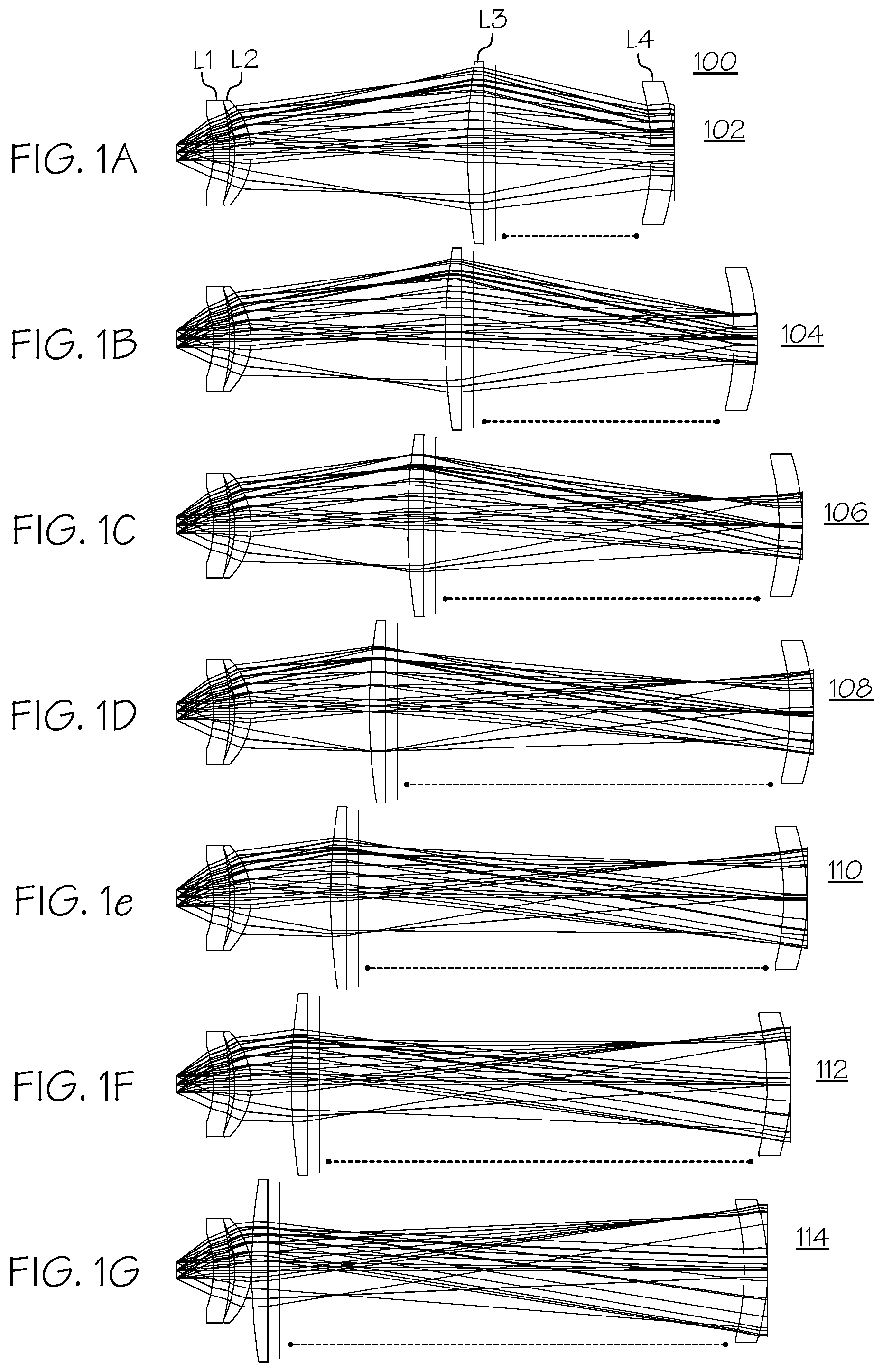
[0024] FIGS. 1A-1G are a schematic diagrams representing various lens positions and corresponding light paths through lenses of the continuous zoom afocal device in accordance with embodiments of the present disclosure.
[0025] FIG. 2 is a schematic diagram of a side view of the continuous zoom afocal device in accordance with embodiments of the present disclosure.
[0026] FIG. 3 is a schematic diagram of a first perspective view of the continuous zoom afocal device in accordance with embodiments of the present disclosure.
[0027] FIG. 4 is a schematic diagram of a second perspective view of the continuous zoom afocal device in accordance with embodiments of the present disclosure.
[0028] FIG. 5 is a schematic diagram of a semi-transparent side view of the continuous zoom afocal device in accordance with embodiments of the present disclosure.
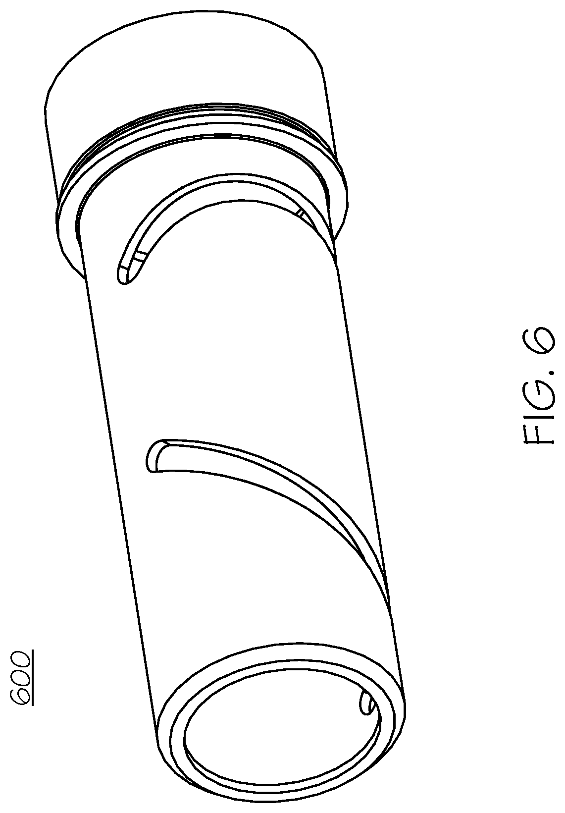
[0029] FIG. 6 is a schematic diagram of an example worm drive cam in accordance with embodiments of the present disclosure.
DETAILED DESCRIPTION
[0030] This disclosure describes a continuous zoom afocal device that facilitates smooth zooming. Afocal attachments of different magnifications are desirable for use in thermally calibrated fixed focal length long wavelength infrared (LWIR) optical systems. Though thermal imaging applications are discussed above, the continuous zoom afocal device described herein can also be used for visible optical applications.
[0031] A benefit of the design presented herein is that the lens that is already mounted and calibrated on the camera itself does not need to be removed.
[0032] A design is presented herein that includes and claims:
[0033] An optical device that facilitates movement of two groups of lenses synchronously. Such movement can be facilitated by a worm drive, for example, or by other mechanisms.
[0034] A long wavelength infrared (LWIR) afocal zoom lens with spherical elements that zooms from X to Y magnification.
[0035] A LWIR afocal zoom lens that is designed for good performance over a 74 degree field of vision (FoV) at a sensor side of the optical device.
[0036] A LWIR afocal zoom lens that even with large FoV has no vignetting.
[0037] A LWIR afocal zoom lens that forms an intermediate image within the lens such that the moveable zoom element is in the vicinity of the intermediate image and functions to provide variable power for the zoom function and also functions as a field lens, bending the light flux in such a way as to both minimize lens diameters and avoid vignetting.
[0038] In some implementations, the lens assembly can include 4 optical elements. In some implementation, the adapter includes 4 optical elements. The first two elements L1 and L2 are fixed, the third L3 is moveable and provides the zoom function, while the fourth element L4 moves to provide focus adjustment.
[0039] In some implementations, the lens assembly can include three elements, wherein one of the elements is aspheric.
[0040] There are other implementations where better color correction is desired, and is accomplished by way of a diffractive surface on one of the lens elements
[0041] The lens in various zoom configurations is shown in FIGS. 1A-1G. FIGS. 1A-1G are schematic illustrations of the lens assembly 100 for a continuous zoom afocal optical device. FIG. 1A illustrates the lens assembly 100 in a first configuration 102. The lens assembly 100 includes four lenses: a first lens L1 and a second lens L2 can be stationary, immovable lenses secured within a housing (as shown in FIG. 5). The first lens L1 and the second lens L2 can be focusing lenses that focus light towards a light detector.
[0042] The lens assembly 100 can include a third lens L3. The third lens L3 can be a zoom lens that can move along a long axis of a housing. In some embodiments, the third lens L3 can also rotate about the long axis as the third lens L3 translates along the long axis of the housing (shown in FIG. 5). The lens assembly 100 also includes a fourth lens L4, which can be an objective L4. The fourth lens L4 can also move for focusing adjustment. As shown in the FIGS. 1A-1G, the third lens L3 and the fourth lens L4 and can move synchronously to provide continuous zoom in the afocal lens configuration.
[0043] FIGS. 1A-1G illustrate various lens positions, as well as example optical light rays representing how light is refracted through the lenses. The relative position of the third lens L3 to the fourth lens L4 is illustrated by a dotted line segment. In FIG. 1A, a first lens position 102 is illustrated. This lens position 102 can be representative of a first magnification of light entering the fourth lens L4. In FIG. 1B, a second lens position 104 is illustrated. This second lens position 102 can be representative of a second magnification of light entering the fourth lens L4. In FIG. 1C, a third lens position 106 is illustrated. This third lens position 106 can be representative of a third magnification of light entering the fourth lens L4. In FIG. 1D, a fourth lens position 108 is illustrated. This fourth lens position 108 can be representative of a fourth magnification of light entering the fourth lens L4. In FIG. 1E, a fifth lens position 110 is illustrated. This fifth lens position 110 can be representative of a fifth magnification of light entering the fourth lens L4. In FIG. 1F, a sixth lens position 112 is illustrated. This sixth lens position 112 can be representative of a sixth magnification of light entering the fourth lens L4. In FIG. 1G, a seventh lens position 114 is illustrated. This seventh lens position 114 can be representative of a seventh magnification of light entering the fourth lens L4.
[0044] Table 1 provides a non-limiting example of the effective focal length of L1, L2 and L3, along with the focal length of L4. The ratio corresponds to the zoom. Additionally the optical "work," meaning the optical power multiplied by the zero field ray height, of L3 is shown. Where the values are low, that indicates where L3 is functioning primarily as a field lens.
TABLE-US-00001 TABLE 1 Focal length of Focal length of Optical "work" of Zoom L1, L2 and L3 L4 L3 2 23.2 47.82 0.0558 3 15.5 47.82 0.0366 4 11.8 47.82 0.0175 5 9.5 47.82 0 6 7.9 47.82 -0.02 7 6.8 47.82 -0.038 8 5.9 47.82 -0.05
[0045] FIG. 2 is a schematic diagram of a side view of the continuous zoom afocal optical device 200 in accordance with embodiments of the present disclosure. In FIG. 2, the continuous zoom afocal device is shown with a housing 202 covering the lens assembly (e.g., lens assembly 100). The housing 202 can contain other features of the device 200, including, but not limited to a lens driving mechanism, such as a worm drive, a light detector element, such as a LWIR detector element, a display element, power circuitry and battery, etc.
[0046] A zoom+focus adjustment knob 204 is shown. The zoom+focus adjustment knob 204 is configured to adjust the third lens L3 and the fourth lens L4 synchronously to provide continuous zoom capability. A battery cap 206 is also shown in FIG. 2, which can contain a lithium or other type of batter to supply power to various powered elements of the optical device 200.
[0047] FIG. 3 is a schematic diagram of a first perspective view of the continuous zoom afocal optical device 200 in accordance with embodiments of the present disclosure. In FIG. 3, the objective lens (fourth lens L4) is shown proximate the zoom+focus adjustment knob 204. FIG. 4 is a schematic diagram of a second perspective view of the continuous zoom afocal optical device 200 in accordance with embodiments of the present disclosure. The view screen 208 is shown on one end of the device, on a side opposite the zoom+focus adjustment knob 204.
[0048] FIG. 5 is a schematic diagram of a semi-transparent side view of the continuous zoom afocal optical device 200 in accordance with embodiments of the present disclosure. The lenses L1, L2, L3, and L4 are shown in an example, non-limiting lens position. The mechanism to move the lenses can include a worm drive, a motor-driven track, or other technique for moving the lenses. An example worm cam 600 is illustrated in FIG. 6. FIG. 6 is a schematic diagram of an example worm drive cam 600 in accordance with embodiments of the present disclosure. The worm drive cam 600 can include slots for receiving worm drive pins for controlling the position of the third lens L3 and the fourth lens L4 relative to each other during zoom+focus adjustment.
[0049] The third lens L3 and the fourth lens L4 can move along a direction parallel to the long axis 220 of the housing. In embodiments, the third lens L3 and the fourth lens L4 can also rotate about the long axis 220 as the third lens L3 and the fourth lens L4 translate along the axis 220.
[0050] The zoom+focus adjustment knob 204 is configured to rotate, and upon rotation, can move the third lens L3 and the fourth lens L4, in a configuration similar to that shown in FIGS. 1A-G.
[0051] Reference throughout this specification to "one embodiment" or "an embodiment" means that a particular feature, structure, or characteristic described in connection with the embodiment is included in at least one embodiment of the present invention. Thus, the appearances of the phrases "in one embodiment" or "in an embodiment" in various places throughout this specification are not necessarily all referring to the same embodiment. Furthermore, the particular features, structures, or characteristics may be combined in any suitable manner in one or more embodiments.
[0052] In the foregoing specification, a detailed description has been given with reference to specific exemplary embodiments. It will, however, be evident that various modifications and changes may be made thereto without departing from the broader spirit and scope of the invention as set forth in the appended claims. The specification and drawings are, accordingly, to be regarded in an illustrative sense rather than a restrictive sense. Furthermore, the foregoing use of embodiment and other exemplarily language does not necessarily refer to the same embodiment or the same example, but may refer to different and distinct embodiments, as well as potentially the same embodiment.
* * * * *
D00000
D00001
D00002
D00003
D00004
D00005
D00006
XML
uspto.report is an independent third-party trademark research tool that is not affiliated, endorsed, or sponsored by the United States Patent and Trademark Office (USPTO) or any other governmental organization. The information provided by uspto.report is based on publicly available data at the time of writing and is intended for informational purposes only.
While we strive to provide accurate and up-to-date information, we do not guarantee the accuracy, completeness, reliability, or suitability of the information displayed on this site. The use of this site is at your own risk. Any reliance you place on such information is therefore strictly at your own risk.
All official trademark data, including owner information, should be verified by visiting the official USPTO website at www.uspto.gov. This site is not intended to replace professional legal advice and should not be used as a substitute for consulting with a legal professional who is knowledgeable about trademark law.