Optical Lens
CHEN; Hsin-Te ; et al.
U.S. patent application number 16/393739 was filed with the patent office on 2019-12-05 for optical lens. This patent application is currently assigned to Rays Optics Inc.. The applicant listed for this patent is Rays Optics Inc.. Invention is credited to Ching-Sheng CHANG, Hsin-Te CHEN, Kuo-Chuan WANG.
| Application Number | 20190369363 16/393739 |
| Document ID | / |
| Family ID | 68694699 |
| Filed Date | 2019-12-05 |


View All Diagrams
| United States Patent Application | 20190369363 |
| Kind Code | A1 |
| CHEN; Hsin-Te ; et al. | December 5, 2019 |
OPTICAL LENS
Abstract
An optical lens includes a first lens group, a second lens group and an aperture stop disposed between the first lens group and the second lens group. The optical lens satisfies the conditions of 7 mm<D<25 mm and 0.3<D/LT<0.5, where D is a diameter of a lens surface of the second lens group furthest from the first lens group and LT is a total lens length measured along an optical axis between a lens surface of the first lens group furthest from the second lens group and the lens surface of the second lens group furthest from the first lens group.
| Inventors: | CHEN; Hsin-Te; (Hsinchu County, TW) ; CHANG; Ching-Sheng; (Hsinchu County, TW) ; WANG; Kuo-Chuan; (Hsinchu County, TW) | ||||||||||
| Applicant: |
|
||||||||||
|---|---|---|---|---|---|---|---|---|---|---|---|
| Assignee: | Rays Optics Inc. |
||||||||||
| Family ID: | 68694699 | ||||||||||
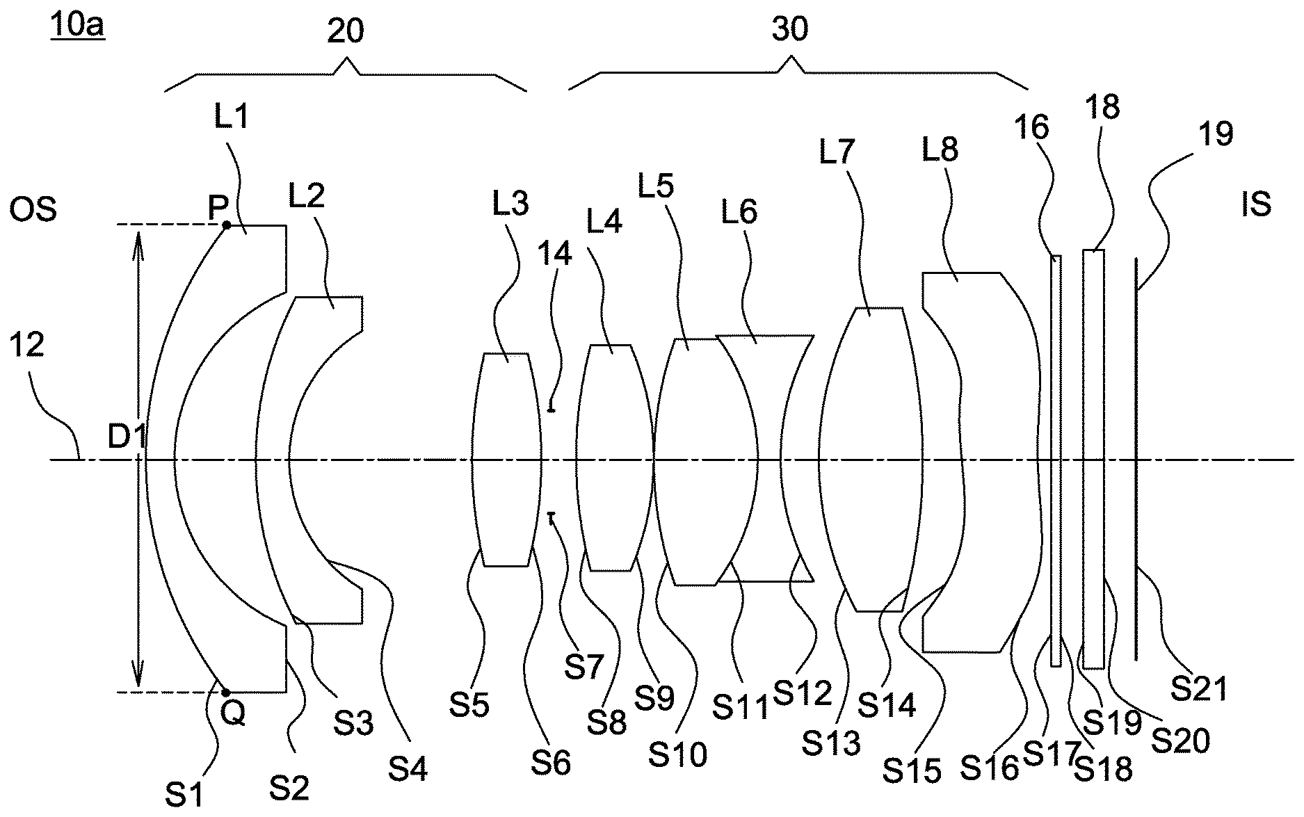
| Appl. No.: | 16/393739 | ||||||||||
| Filed: | April 24, 2019 |
| Current U.S. Class: | 1/1 |
| Current CPC Class: | G02B 13/002 20130101; G02B 13/0045 20130101; G02B 15/16 20130101; G02B 13/006 20130101; G02B 9/62 20130101; G02B 9/64 20130101; G02B 27/64 20130101; G02B 7/04 20130101 |
| International Class: | G02B 13/00 20060101 G02B013/00; G02B 15/16 20060101 G02B015/16; G02B 9/62 20060101 G02B009/62; G02B 9/64 20060101 G02B009/64; G02B 27/64 20060101 G02B027/64; G02B 7/04 20060101 G02B007/04 |
Foreign Application Data
| Date | Code | Application Number |
|---|---|---|
| May 31, 2018 | TW | 107118817 |
| Nov 8, 2018 | TW | 107139657 |
Claims
1. An optical lens, comprising: a first lens group comprising at least two lenses with refractive powers; a second lens group with a positive refractive power and comprising a doublet lens; and an aperture stop disposed between the first lens group and the second lens group, wherein a total number of lenses with refractive powers in the optical lens is more than four and less than eleven, and the optical lens satisfies the conditions: 7 mm<D<25 mm and 0.3<D/LT<0.5 , where D is a diameter of a lens surface of the second lens group furthest from the first lens group and LT is a total lens length measured along an optical axis between a lens surface of the first lens group furthest from the second lens group and the lens surface of the second lens group furthest from the first lens group.
2. The optical lens as claimed in claim 1, wherein at least two lenses of the optical lens have an Abbe number of greater than 65.
3. The optical lens as claimed in claim 1, wherein an F-number of the optical lens is larger than or equal to 2.2.
4. The optical lens as claimed in claim 1, wherein the first lens group of the optical lens comprises at least one aspheric lens, and the second lens group of the optical lens comprises only one aspheric lens.
5. The optical lens as claimed in claim 1, wherein all lenses of the optical lens are made from glass.
6. The optical lens as claimed in claim 1, wherein the total lens length is smaller than 30 mm.
7. The optical lens as claimed in claim 1, wherein the optical lens satisfies one of the following conditions: (1) the optical lens comprises eight lenses having respective shapes of meniscus, aspheric, biconvex, biconvex, biconvex, biconcave, biconvex and aspheric in order from a magnified side to a minified side; (2) the optical lens comprises seven lenses having respective shapes of meniscus, aspheric, biconvex, biconcave, biconvex, biconvex and aspheric in order from the magnified side to the minified side; (3) the optical lens comprises seven lenses having respective shapes of aspheric, meniscus, biconvex, biconvex, meniscus, meniscus, and aspheric in order from the magnified side to the minified side; (4) the optical lens comprises seven lenses having respective shapes of meniscus, biconcave, biconvex, biconcave, biconvex, biconvex, and aspheric in order from the magnified side to the minified side.
8. The optical lens as claimed in claim 1, wherein the optical lens satisfies one of the following conditions: (1) the optical lens has eight lenses with refractive powers of negative, negative, positive, positive, positive, negative, positive and negative in order from a magnified side to a minified side; (2) the optical lens has seven lenses with refractive powers of negative, negative, positive, negative, positive, positive and negative in order from the magnified side to the minified side; (3) the optical lens has seven lenses with refractive powers of negative, negative, positive, positive, negative, positive and negative in order from the magnified side to the minified side.
9. An optical lens, comprising: a first lens, a second lens, a compound lens having at least two lenses, and an aspheric lens arranged in order from a magnified side to a minified side, wherein adjoining surfaces of two adjacent lenses of the compound lens have a substantial identical radius of curvature, a total number of lenses with refractive powers in the optical lens is more than four and less than eleven, and the optical lens satisfies the conditions: LT/IMH25<12, and LT/IMH45<6.5 , where LT is a total lens length measured along an optical axis between a lens surface of the first lens closest to the magnified-side and a lens surface of the aspheric lens closest to the minified-side, IMH25 is a semi-diagonal image height on an image plane measured at a half field of view of 25 degrees, and IMH 45 is a semi-diagonal image height on the image plane measured at a half field of view of 45 degrees.
10. The optical lens as claimed in claim 9, wherein at least two lenses of the optical lens have an Abbe number of greater than 65.
11. The optical lens as claimed in claim 9, wherein an F-number of the optical lens is larger than or equal to 2.2.
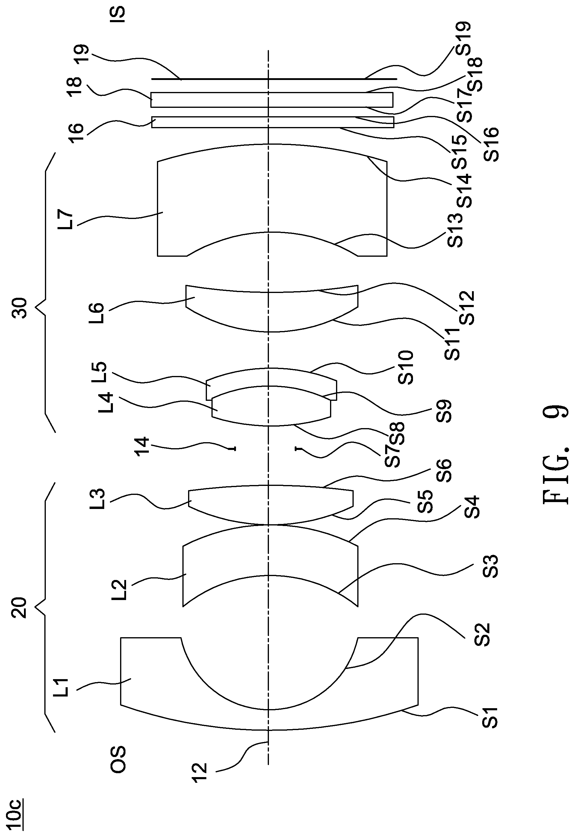
12. The optical lens as claimed in claim 9, wherein all lenses of the optical lens are made from glass.
13. The optical lens as claimed in claim 9, wherein the total lens length is smaller than 30 mm.
14. The optical lens as claimed in claim 9, wherein the optical lens satisfies one of the following conditions: (1) the optical lens comprises eight lenses having respective shapes of meniscus, aspheric, biconvex, biconvex, biconvex, biconcave, biconvex and aspheric in order from the magnified side to the minified side; (2) the optical lens comprises seven lenses having respective shapes of meniscus, aspheric, biconvex, biconcave, biconvex, biconvex and aspheric in order from the magnified side to the minified side; (3) the optical lens comprises seven lenses having respective shapes of aspheric, meniscus, biconvex, biconvex, meniscus, meniscus, and aspheric in order from the magnified side to the minified side; (4) the optical lens comprises seven lenses having respective shapes of meniscus, biconcave, biconvex, biconcave, biconvex, biconvex, and aspheric in order from the magnified side to the minified side.
15. The optical lens as claimed in claim 9, wherein the optical lens satisfies one of the following conditions: (1) the optical lens has eight lenses with refractive powers of negative, negative, positive, positive, positive, negative, positive and negative in order from the magnified side to the minified side; (2) the optical lens has seven lenses with refractive powers of negative, negative, positive, negative, positive, positive and negative in order from the magnified side to the minified side; (3) the optical lens has seven lenses with refractive powers of negative, negative, positive, positive, negative, positive and negative in order from the magnified side to the minified side.
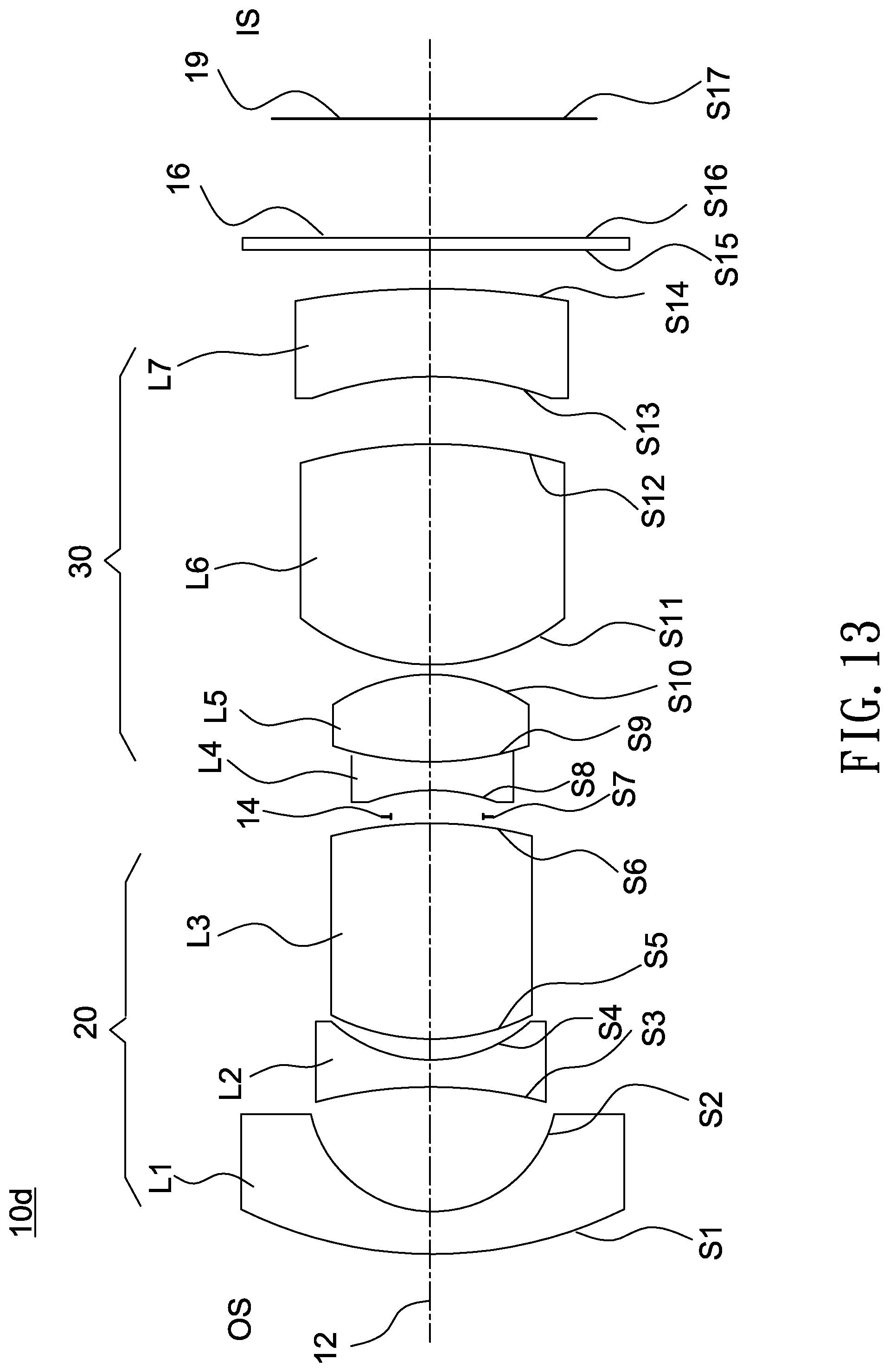
16. An optical lens, comprising: a first lens group comprising a first lens and a second lens; and a second lens group with a positive refractive power comprising an aspheric lens and a compound lens having at least two lenses, wherein a ratio of a relative illumination measured at a highest position of an image height on an image plane to a relative illumination measured at a position of the optical axis on the image plane of the optical lens is larger than 35%, and the optical lens satisfies the condition: 7 mm<D<25 mm , where D is a diameter of a lens surface of the second lens group furthest from the first lens group.
17. The optical lens as claimed in claim 16, wherein at least two lenses of the optical lens have an Abbe number of greater than 65.
18. The optical lens as claimed in claim 16, wherein an F-number of the optical lens is larger than or equal to 2.2.
19. The optical lens as claimed in claim 16, wherein the optical lens satisfies one of the following conditions: (1) the optical lens comprises eight lenses having respective shapes of meniscus, aspheric, biconvex, biconvex, biconvex, biconcave, biconvex and aspheric in order from a magnified side to a minified side; (2) the optical lens comprises seven lenses having respective shapes of meniscus, aspheric, biconvex, biconcave, biconvex, biconvex and aspheric in order from the magnified side to the minified side; (3) the optical lens comprises seven lenses having respective shapes of aspheric, meniscus, biconvex, biconvex, meniscus, meniscus, and aspheric in order from the magnified side to the minified side; (4) the optical lens comprises seven lenses having respective shapes of meniscus, biconcave, biconvex, biconcave, biconvex, biconvex, and aspheric in order from the magnified side to the minified side.
20. The optical lens as claimed in claim 16, wherein the optical lens satisfies one of the following conditions: (1) the optical lens has eight lenses with refractive powers of negative, negative, positive, positive, positive, negative, positive and negative in order from a magnified side to a minified side; (2) the optical lens has seven lenses with refractive powers of negative, negative, positive, negative, positive, positive and negative in order from the magnified side to the minified side; (3) the optical lens has seven lenses with refractive powers of negative, negative, positive, positive, negative, positive and negative in order from the magnified side to the minified side.
Description
BACKGROUND OF THE INVENTION
a. Field of the Invention
[0001] The invention relates to an optical lens.
b. Description of the Related Art
[0002] Recent advances in technology have led to the development of various types of optical lenses. For example, an automotive lens mounted on a vehicle is a commonly used optical lens. Nowadays, there is a growing need for an optical lens to become thinner and have high optical performance. To meet these requirements, the optical lens needs to have low fabrication costs, high resolution, large effective apertures, large target areas, wide ranges of operating temperatures and light weight. Therefore, it is desirable to provide an optical lens that may achieve lighter weight, lower fabrication costs, wider ranges of operating temperatures and better imaging quality.
BRIEF SUMMARY OF THE INVENTION
[0003] According to one aspect of the present disclosure, an optical lens includes a first lens group, a second lens group and an aperture stop. The first lens group includes at least two lenses with refractive powers, the second lens group has a positive refractive power and includes a doublet lens, and the aperture stop is disposed between the first lens group and the second lens group. A total number of lenses with refractive powers in the optical lens is more than four and less than eleven. The optical lens satisfies the conditions of 7 mm<D<25 mm and 0.3<D/LT<0.5, where D is a diameter of a lens surface of the second lens group furthest from the first lens group and LT is a total lens length measured along an optical axis between a lens surface of the first lens group furthest from the second lens group and the lens surface of the second lens group furthest from the first lens group. Accordingly, the optical lens may achieve good imaging quality, reduced fabrication costs, wider operating temperature ranges, lighter weight, miniaturization, and a reduced total lens number of 5-10.
[0004] According to another aspect of the present disclosure, an optical lens includes a first lens, a second lens, a compound lens having at least two lenses, and an aspheric lens arranged in order from a magnified side to a minified side. Adjoining surfaces of two adjacent lenses of the compound lens have a substantial identical radius of curvature, and a total number of lenses with refractive powers in the optical lens is more than four and less than eleven. The optical lens satisfies the conditions of LT/IMH25<12, and LT/IMH45<6.5, where LT is a total lens length measured along an optical axis between a lens surface of the first lens closest to the magnified-side and a lens surface of the aspheric lens closest to the minified-side, IMH25 is a semi-diagonal image height on an image plane measured at a half field of view of 25 degrees, and IMH 45 is a semi-diagonal image height on the image plane measured at a half field of view of 45 degrees. Accordingly, the optical lens may achieve good imaging quality, reduced fabrication costs, wider operating temperature ranges, lighter weight, miniaturization, and a reduced total lens number of 5-10.
[0005] According to another aspect of the present disclosure, an optical lens includes a first lens group and a second lens group. The first lens group includes a first lens and a second lens, and the second lens group with a positive refractive power includes an aspheric lens and a compound lens having at least two lenses. A ratio of a relative illumination measured at a highest position of an image height on an image plane to a relative illumination measured at a position of the optical axis on the image plane of the optical lens is larger than 35%. The optical lens satisfies the condition of 7 mm<D<25 mm, where D is a diameter of a lens surface of the second lens group furthest from the first lens group. Accordingly, the optical lens may achieve good imaging quality, reduced fabrication costs, wider operating temperature ranges, lighter weight, miniaturization, and a reduced total lens number of 5-10.
[0006] According to the above aspects, the optical lens may achieve good imaging quality, reduced fabrication costs and lighter weight and is favorable for miniaturization. Further, according to the above embodiments, the optical lens is allowed to operate at -40.degree. C. to 105.degree. C. and has a total lens number of 5 to 10. Therefore, the optical lens may achieve good imaging quality and resolution, lower fabrication costs, larger effective apertures, lighter weight and wide ranges of operating temperatures.
[0007] Other objectives, features and advantages of the invention will be further understood from the further technological features disclosed by the embodiments of the invention wherein there are shown and described preferred embodiments of this invention, simply by way of illustration of modes best suited to carry out the invention.
BRIEF DESCRIPTION OF THE DRAWINGS
[0008] FIG. 1 shows a cross-sectional illustration of an optical lens according to an embodiment of the invention.
[0009] FIGS. 2-4 respectively show ray fan plots, MTF curves and a relative illumination curve and corresponding numerical values and ratios of relative illumination of the optical lens shown in FIG. 1.
[0010] FIG. 5 shows a cross-sectional illustration of an optical lens according to another embodiment of the invention.
[0011] FIGS. 6-8 respectively show ray fan plots, MTF curves and a relative illumination curve and corresponding numerical values and ratios of relative illumination of the optical lens shown in FIG. 5.
[0012] FIG. 9 shows a cross-sectional illustration of an optical lens according to another embodiment of the invention.
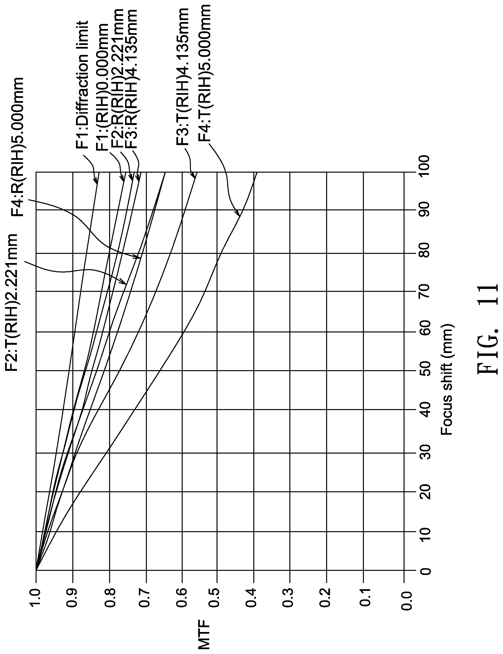
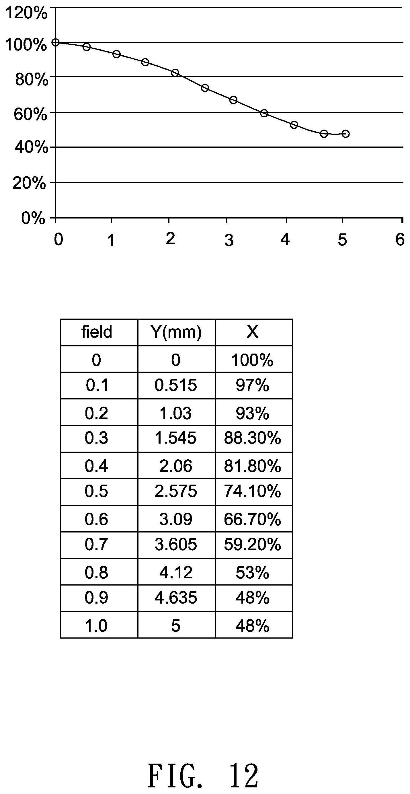
[0013] FIGS. 10-12 respectively show ray fan plots, MTF curves and a relative illumination curve and corresponding numerical values and ratios of relative illumination of the optical lens shown in FIG. 9.
[0014] FIG. 13 shows a cross-sectional illustration of an optical lens according to another embodiment of the invention.
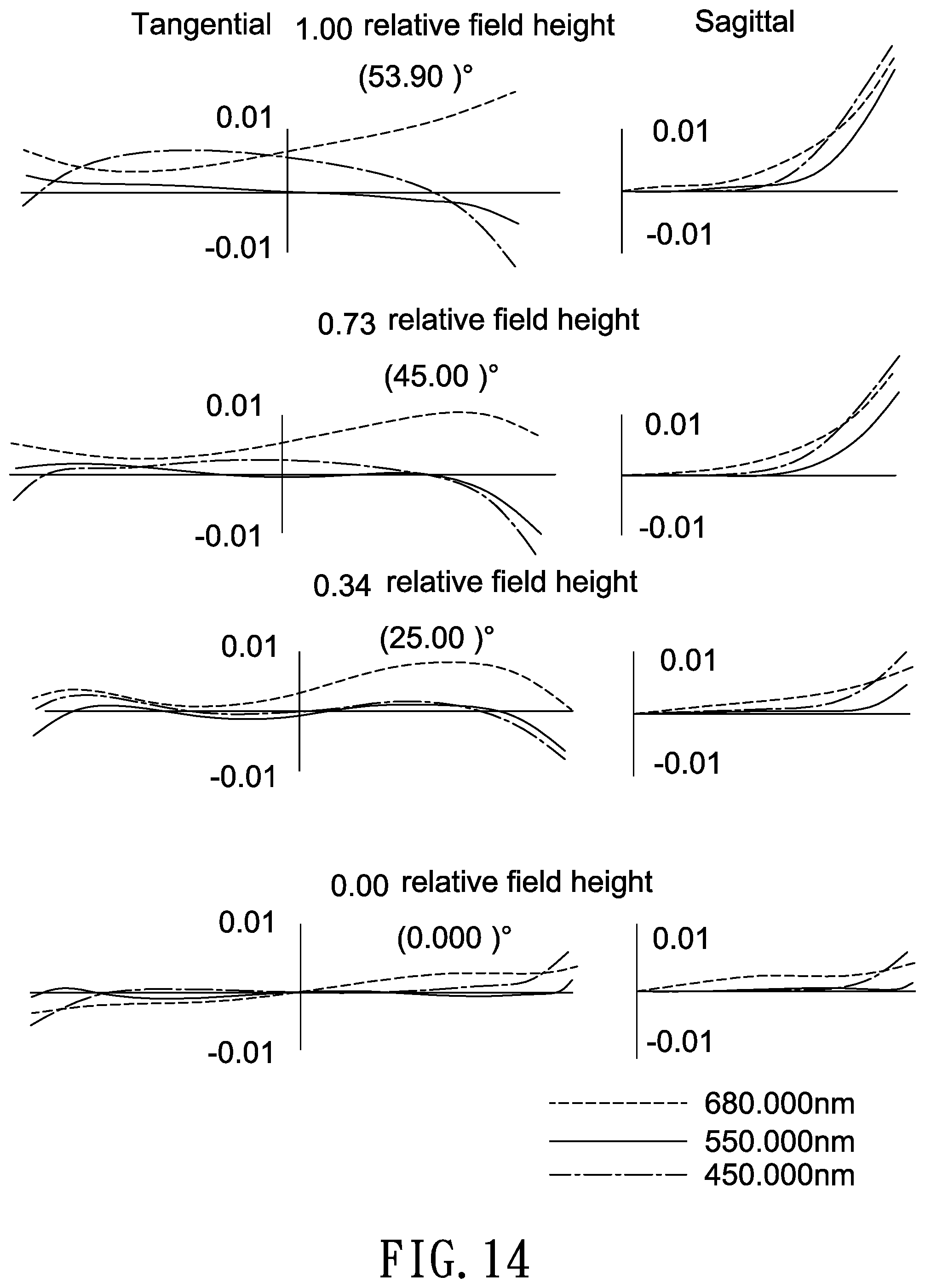
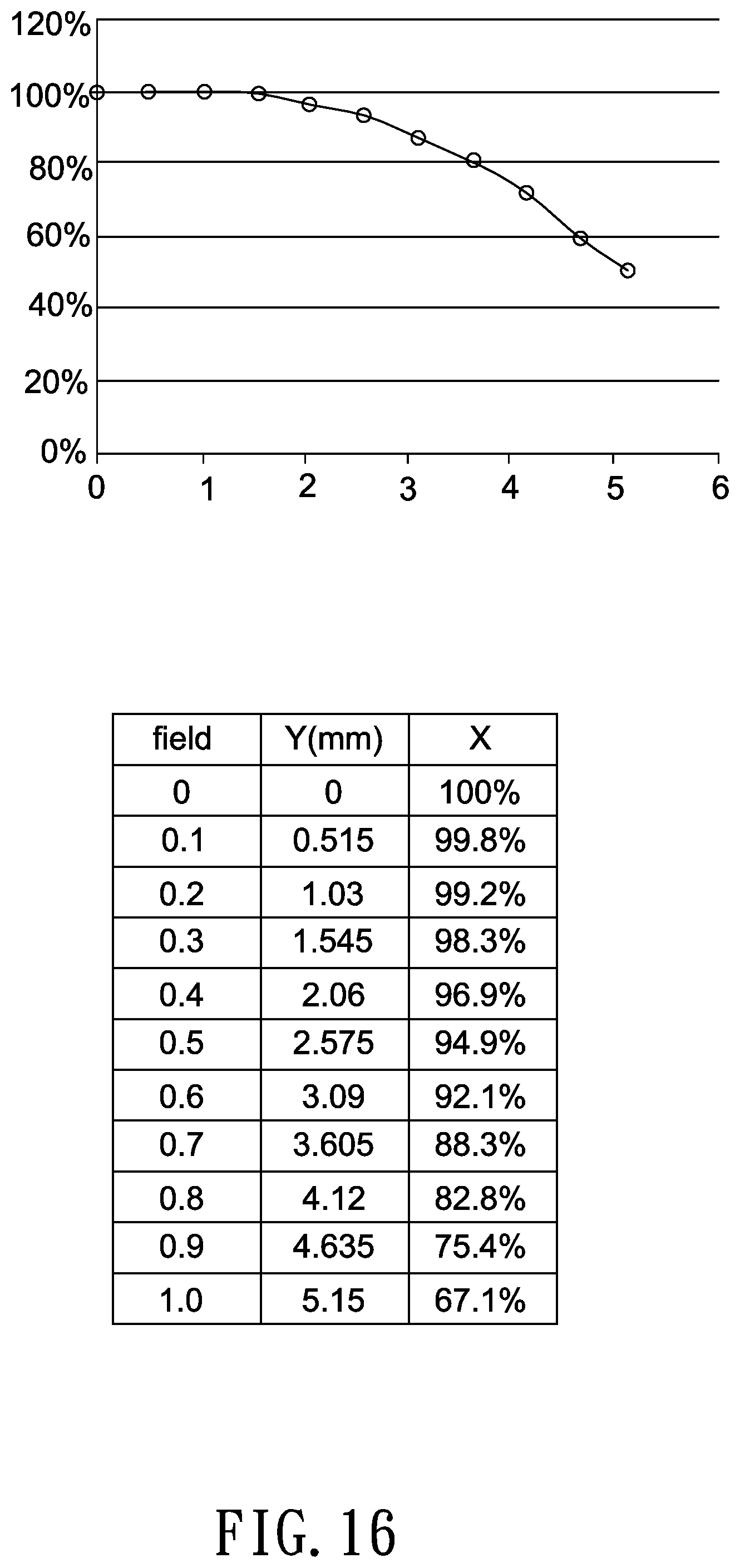
[0015] FIGS. 14-16 respectively show ray fan plots, MTF curves and a relative illumination curve and corresponding numerical values and ratios of relative illumination of the optical lens shown in FIG. 13.
[0016] FIG. 17 shows a cross-sectional illustration of an optical lens according to another embodiment of the invention.
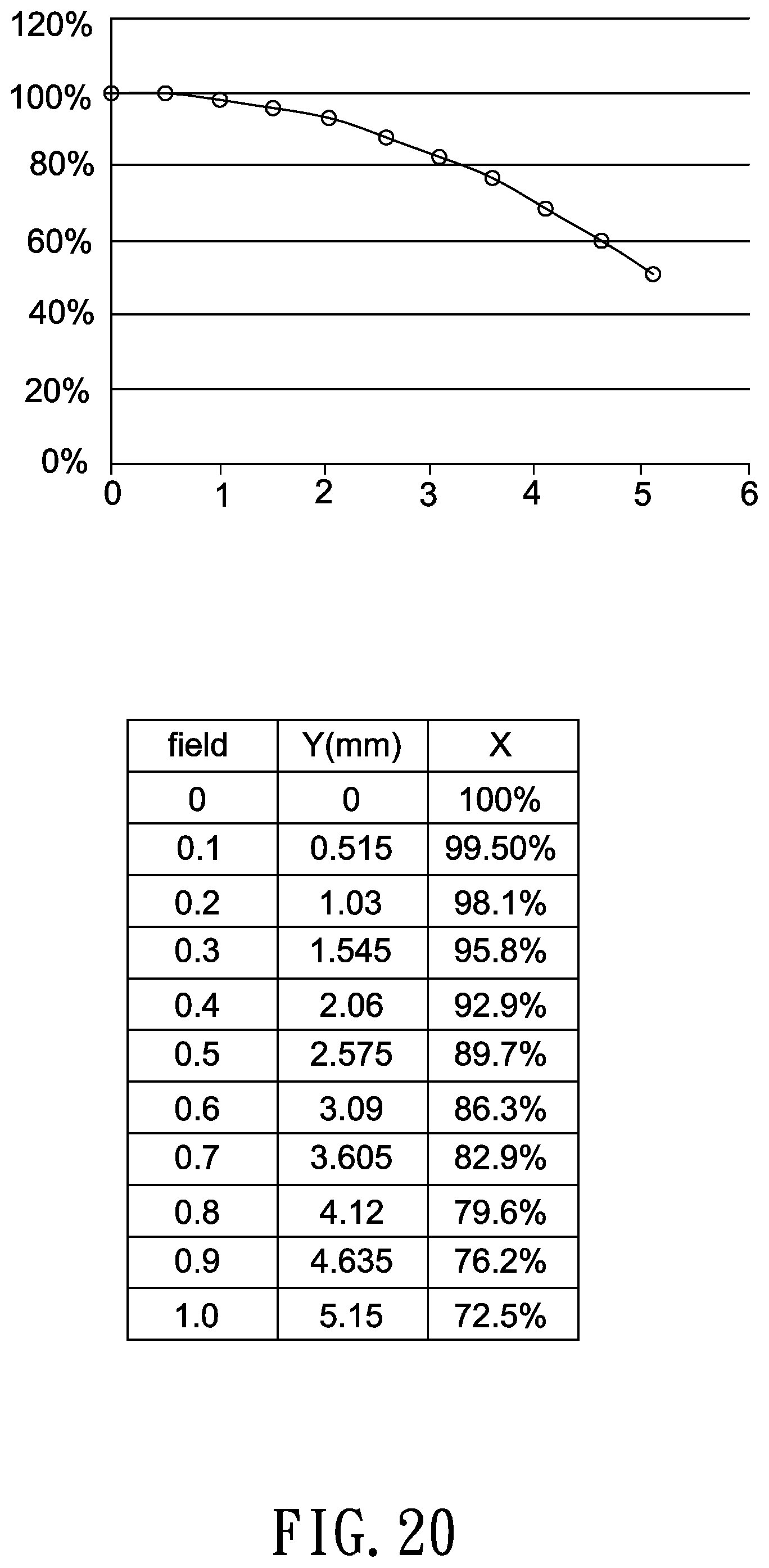
[0017] FIGS. 18-20 respectively show ray fan plots, MTF curves and a relative illumination curve and corresponding numerical values and ratios of relative illumination of the optical lens shown in FIG. 17.
DETAILED DESCRIPTION OF THE INVENTION
[0018] In the following detailed description of the preferred embodiments, directional terminology, such as "top," "bottom," "front," "back," etc., is used with reference to the orientation of the Figure(s) being described. The components of the invention can be positioned in a number of different orientations. As such, the directional terminology is used for purposes of illustration and is in no way limiting. Further, "First," "Second," etc, as used herein, are used as labels for nouns that they precede, and do not imply any type of ordering (e.g., spatial, temporal, logical, etc.).
[0019] The term "optical element" refers to an element made from at least in part a material that may refract, reflect, diffract, diffuse or filter at least a portion of the light passing through it. The material may include plastic or glass, and the optical element may be, for example, a lens, a prism or an aperture stop.
[0020] In an image-pickup system, a magnified side may refer to one side of an optical path of an optical lens comparatively near a subject to be picked-up, and a minified side may refer to other side of the optical path comparatively near a photosensor.
[0021] A certain region of an object side surface (or an image side surface) of a lens may be convex or concave. Herein, a convex or concave region is more outwardly convex or inwardly concave in the direction of an optical axis as compared with other neighboring regions of the object/image side surface.
[0022] FIG. 1 shows a cross-sectional illustration of an optical lens according to an embodiment of the invention. As shown in FIG. 1, in this embodiment, the optical lens 10a has a lens barrel (not shown), and inside the lens barrel a first lens L1, a second lens L2, a third lens L3, an aperture stop 14, a fourth lens L4, a fifth lens L5, a sixth lens L6, a seventh lens L7 and a eighth lens L8 are arranged in order from a first side (magnified side OS) to a second side (minified side IS). The first lens L1, the second lens L2, and the third lens L3 form a first lens group 20 (such as a front lens group) with a positive refractive power, and the fourth lens L4, the fifth lens L5, the sixth lens L6, the seventh lens L7 and the eighth lens L8 form a second lens group 30 (such as a rear lens group) with a positive refractive power. Further, the minified side IS may be disposed with an IR (infrared) filter 16, a cover glass 18, and a photosensor (not shown), an image plane of the optical lens 10a formed at an effective focal length for visible light is labeled as 19, and the IR filter 16 and the cover glass 18 are disposed between the second lens group 30 and the image plane 19 for visible light. In this embodiment, the refractive powers of the first lens L1 to the eighth lens L8 are negative, negative, positive, positive, positive, negative, positive and negative, and the second lens L2 and the eighth lens L8 are aspheric glass lenses. In one embodiment, the aspheric glass lenses can be replaced with aspheric plastic lenses. In one embodiment, adjoining surfaces of two adjacent lenses may have an identical or a similar radius of curvature and are fit together to form a doublet lens or a triplet lens. For example, in this embodiment, the fifth lens L5 and the sixth lens L6 are fit together to form a doublet lens, but the invention is not limited thereto. In each of the following embodiments, the magnified side OS is located on the left side and the minified side IS is located on the right side of each figure, and thus this is not repeatedly described in the following for brevity.
[0023] The aperture stop 14 may be an independent component or integrally formed with other optical element. In this embodiment, the aperture stop 14 may use a mechanic piece to block out peripheral light and transmit central light to achieve aperture effects. The mechanic piece may be adjusted by varying its position, shape or transmittance. In other embodiment, the aperture stop 14 may be formed by applying an opaque or a light-absorbing material on a lens surface except for a central area to block out peripheral light and transmits central light.
[0024] A lens surface of each lens may be assigned a parameter of "diameter". For example, as shown in FIG. 1, a diameter D1 of a magnified-side surface S1 of the lens L is a distance between opposite turning points P and Q measured in a direction perpendicular to the optical axis 12. Further, in this embodiment, a diameter of the surface S1 is 11.99 mm, and a diameter of the surface S16 is 9.74 mm.
[0025] Detailed design parameters, shapes and aspheric coefficients of the optical lens 10a are shown in Table 1 and Table 2 below. In the following design examples of the invention, each aspheric surface satisfies the following equation:
Z = cr 2 1 + 1 - ( 1 + k ) c 2 r 2 + Ar 4 + Br 6 + Cr 8 + Dr 10 + Er 12 + Fr 14 + , ##EQU00001##
where Z denotes a sag of an aspheric surface along the optical axis, c denotes a reciprocal of a radius of an osculating sphere, k denotes a Conic constant, r denotes a height of the aspheric surface measured in a direction perpendicular to the optical axis 12, and A-F are aspheric coefficients of 4.sup.th, 6.sup.th, 8.sup.th, 10.sup.th, 12.sup.th and 14.sup.th orders. Table 2 lists aspheric coefficients and conic constant of each aspheric surface of the optical lens according to a first embodiment of the invention. Note the data provided below are not used for limiting the invention, and those skilled in the art may suitably modify parameters or settings of the following embodiment with reference of the invention without departing from the scope or spirit of the invention.
TABLE-US-00001 TABLE 1 F/# = 2.2; LT = 22.57 (mm) FOV = 111.14 degrees; D/LT = 0.43 IMH25 = 2.22 (mm); IMH45 = 4.18 (mm) radius of Interval refractive Abbe object surface curvature (mm) (mm) index number description S1 10.12 0.70 1.58 59.37 L1 (meniscus) S2 4.66 2.06 S3* 7.73 0.70 1.52 64.17 L2 (aspheric) S4* 3.35 4.91 S5 45.73 1.49 1.87 40.73 L3 (biconvex) S6 -12.11 0.32 S7 INF. 0.77 aperture stop S8 20.85 1.78 1.50 81.61 L4 (biconvex) S9 -8.29 0.13 S10 11.41 2.53 1.59 67.00 L5 (biconvex) S11 -4.99 0.67 1.69 31.08 L6 (biconcave) S12 6.98 1.07 S13 9.54 2.49 1.55 75.50 L7 (biconvex) S14 -15.47 1.00 S15* -1242.00 1.94 1.81 40.95 L8 (aspheric) S16* 24.92 0.28 S17 INF. 0.21 1.52 64.17 IR filter S18 INF. 0.61 S19 INF. 0.50 1.52 64.17 cover glass S20 INF. 0.83 S21 image plane
TABLE-US-00002 TABLE 2 S3 S4 S15 S16 k 7.281E-01 -7.927E-01 0.000E+00 0.000E+00 A 9.498E-04 3.805E-03 -3.570E-03 -2.500E-03 B -2.166E-04 -1.880E-04 -6.201E-05 -2.719E-05 C 3.405E-06 -8.739E-06 3.088E-06 1.490E-06 D 9.045E-08 5.507E-07 -5.664E-08 -3.063E-08 E -3.044E-09 5.046E-09 -6.716E-09 0.000E+00 F -4.044E-12 -2.461E-10 1.648E-10 0.000E+00
[0026] In the above Table 1, an interval of the surface S1 is a distance between the surface S1 and the surface S2 along the optical axis 12, an interval of the surface S2 is a distance between the surface S2 and the surface S3 along the optical axis 12, and an interval of the surface S20 is a distance between the surface S20 and the image plane 19 for visible light along the optical axis 12.
[0027] In the above table, the surface denoted by an asterisk is an aspheric surface, and a surface without the denotation of an asterisk is a spherical surface.
[0028] The radius of curvature is a reciprocal of the curvature. When a lens surface has a positive radius of curvature, the center of the lens surface is located towards the minified side. When a lens surface has a negative radius of curvature, the center of the lens surface is located towards the magnified side. The concavity and convexity of each lens surface is listed in the above table and shown in corresponding figures.
[0029] The Symbol F/# shown in the above table is an aperture value of the aperture stop. When the optical lens is used in an optical projection system, the image plane is provided on a light valve, and, when the optical lens is used in an image pick-up system, the image plane is a sensing surface of a photosensor.
[0030] When the optical lens is used in an image pick-up system, the image circle refers to a diagonal length of an image on an image plane, and a semi-diagonal image height equals half of the image circle.
[0031] A total lens length of the optical lens 10a is denoted as "LT" in the above table. Specifically, the total lens length LT is a distance along the optical axis 12 between a lens surface S1 closest to the magnified side (magnified-side surface of the lens L1) and a lens surface S16 closest to the minified side (minified-side surface of the lens L8). In one embodiment, the total lens length LT of the optical lens is smaller than 30 mm.
[0032] In this embodiment, FOV denoted in the above table is a light collection angle of the optical surface S1 closest to the magnified side; that is, the FOV is a full field of view measured diagonally.
[0033] In this embodiment, IMH25 denoted in the above table is a semi-diagonal image height on the image plane 19 measured at a half field of view of 25 degrees, and IMH 45 denoted in the above table is a semi-diagonal image height on the image plane 19 measured at a half field of view of 45 degrees.
[0034] In this embodiment, a ratio of an effective focal length of the optical lens to an effective focal length of the first lens group (front lens group) is 0.09, and a ratio of an effective focal length of the optical lens to an effective focal length of the second lens group (rear lens group) is 0.46.
[0035] In one embodiment, the optical lens may include two lens groups, and the front lens group may include two lenses with negative refractive powers, with one of the two lenses being an aspheric lens, to increase light collection efficiency, but the invention is not limited thereto. In one embodiment, an F-number of the optical lens is larger than or equal to 2.2. The rear lens group may include a compound lens (fit together by various ways such as cementing or pressing) and an aspheric lens to correct monochromatic and chromatic aberrations, and thus a minimum distance between two lenses of the rear lens group along an optical axis is smaller than 0.05 mm. The compound lens may be a doublet lens, a triplet lens or even higher number lens configurations. Adjoining surfaces of each two adjacent lenses of the doublet lens, triplet lens or even higher number lens configurations may have an identical or a similar radius of curvature. A total number of lenses with refractive power in the optical lens is 5 to 10 (more than four and less than eleven), and an entrance pupil diameter of the optical lens is greater than 2 mm, such as 2.23 mm in this embodiment. The optical lens may have two lenses with an Abbe number of greater than 65.
[0036] In one embodiment, the optical lens may satisfy a condition of 7 mm<D<25 mm, a further condition of 8 mm<D<20 mm, and a still further condition of 8.5 mm<D<15 mm, where D is a diameter of the lens surface closest to the image plane (a lens surface of the second lens group 30 furthest from the first lens group 20). Meeting the above conditions may facilitate light converging capability of lenses to reduce the scope of image beams passing through lenses to match the size of a photosensor and thus allow for better optical performance in a limited space.
[0037] In one embodiment, the optical lens may satisfy a condition of 0.3<D/LT<0.5, a further condition of 0.32<D/LT<0.48, and a still further condition of 0.35<D/LT<0.47, where D is a diameter of the lens surface closest to the image plane (a lens surface of the second lens group 30 furthest from the first lens group 20) and LT is a total lens length measured along the optical axis 12 between a magnified-side surface of a first lens (a lens surface of the first lens group 20 furthest from the second lens group 30) and a minified-side surface of a last lens (a lens surface of the second lens group 30 furthest from the first lens group 20). Note that this criterion allows for an optimized proportion of a photosensor to a total lens length; that is, providing a proportionally longer total lens length when using a larger photosensor and a proportionally shorter total lens length when using a smaller photosensor.
[0038] In one embodiment, the optical lens may satisfy a condition of LT/IMH25<12 and LT/IMH45<6.5, a further condition of LT/IMH25<11.8 and LT/IMH45<6.4, and a still further condition of LT/IMH25<11.6 and LT/IMH45<6.3, where LT is a total lens length measured along the optical axis 12 between a magnified-side surface of a first lens (a lens surface of the first lens group 20 furthest from the second lens group 30) and a minified-side surface of a last lens (a lens surface of the second lens group 30 furthest from the first lens group 20), IMH25 is a semi-diagonal image height on the image plane measured at a half field of view of 25 degrees, and IMH 45 is a semi-diagonal image height on the image plane measured at a half field of view of 45 degrees. Note that this criterion allows for an optimized proportion of a photosensor to a total lens length; that is, providing a proportionally longer total lens length when using a larger photosensor and a proportionally shorter total lens length when using a smaller photosensor.
[0039] Typically, the parameter of "relative illumination" is generally given as a percentage of illumination at any point on the sensor normalized to the position in the field with maximum illumination. In one embodiment, a ratio of the relative illumination measured at a highest position of an image height on the image plane to the relative illumination measured at a position of the optical axis on the image plane is larger than 35%. In another embodiment, the same ratio is larger than 38%, and, in a still further embodiment, the same ratio is larger than 40%.
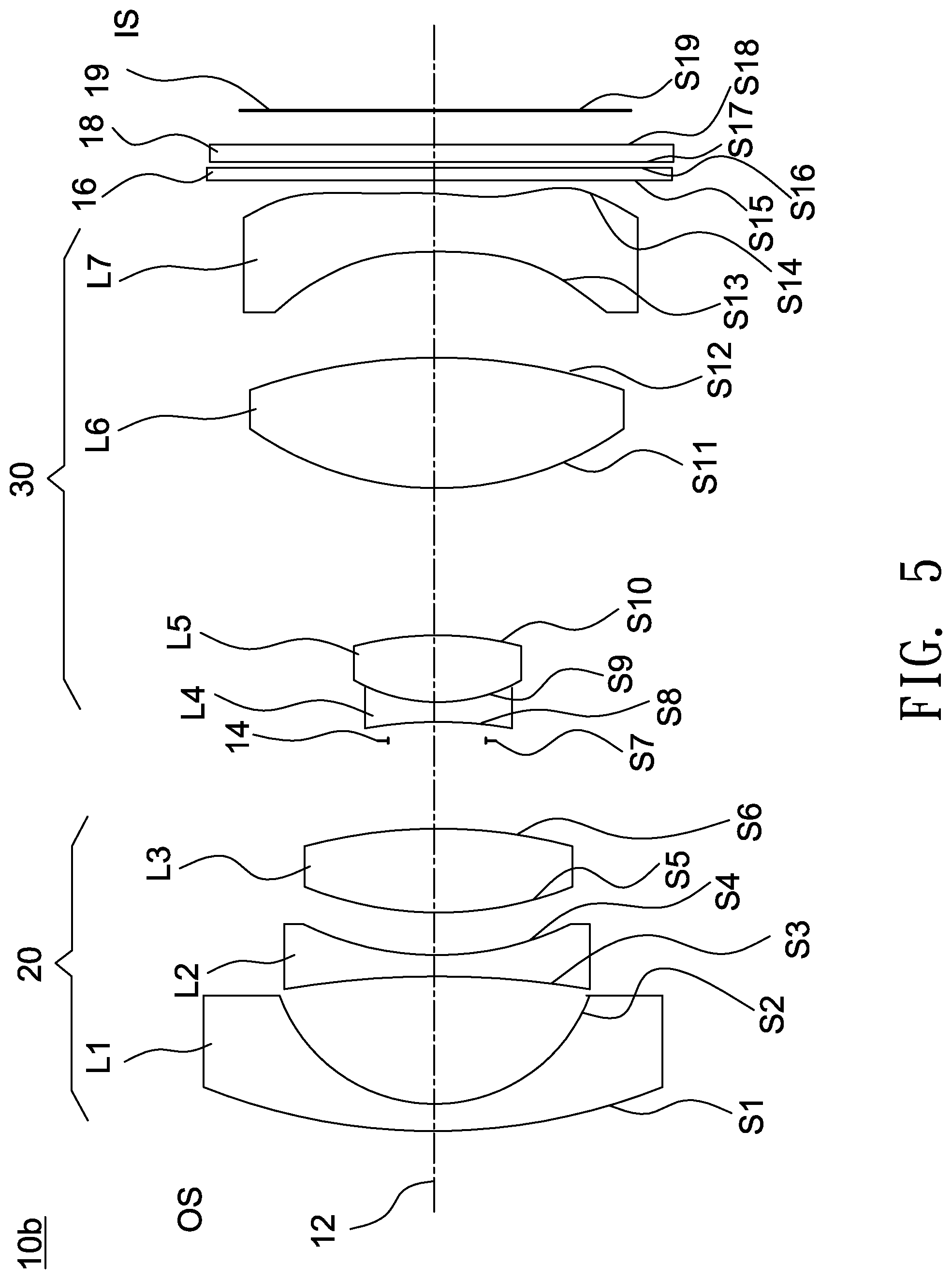
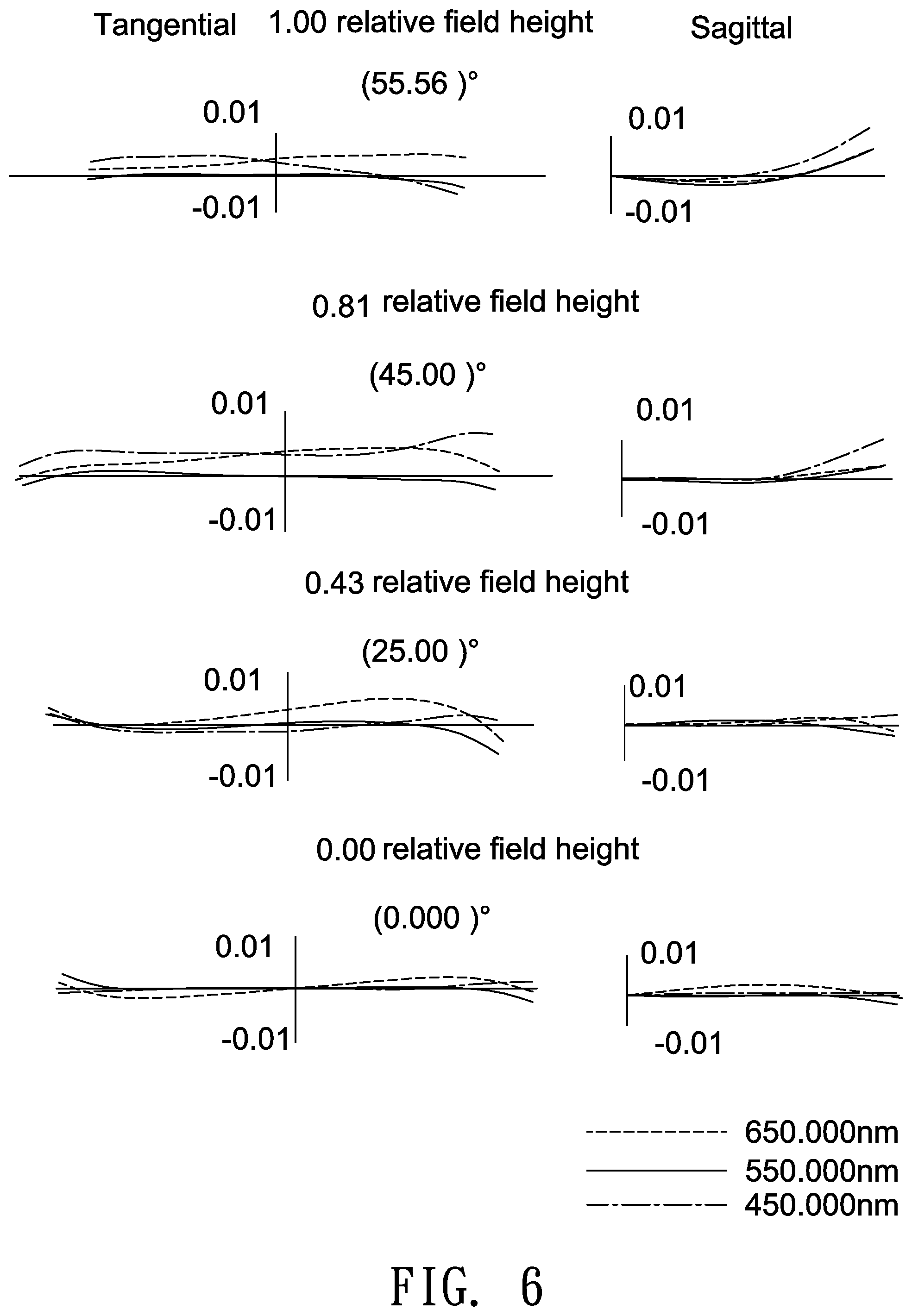
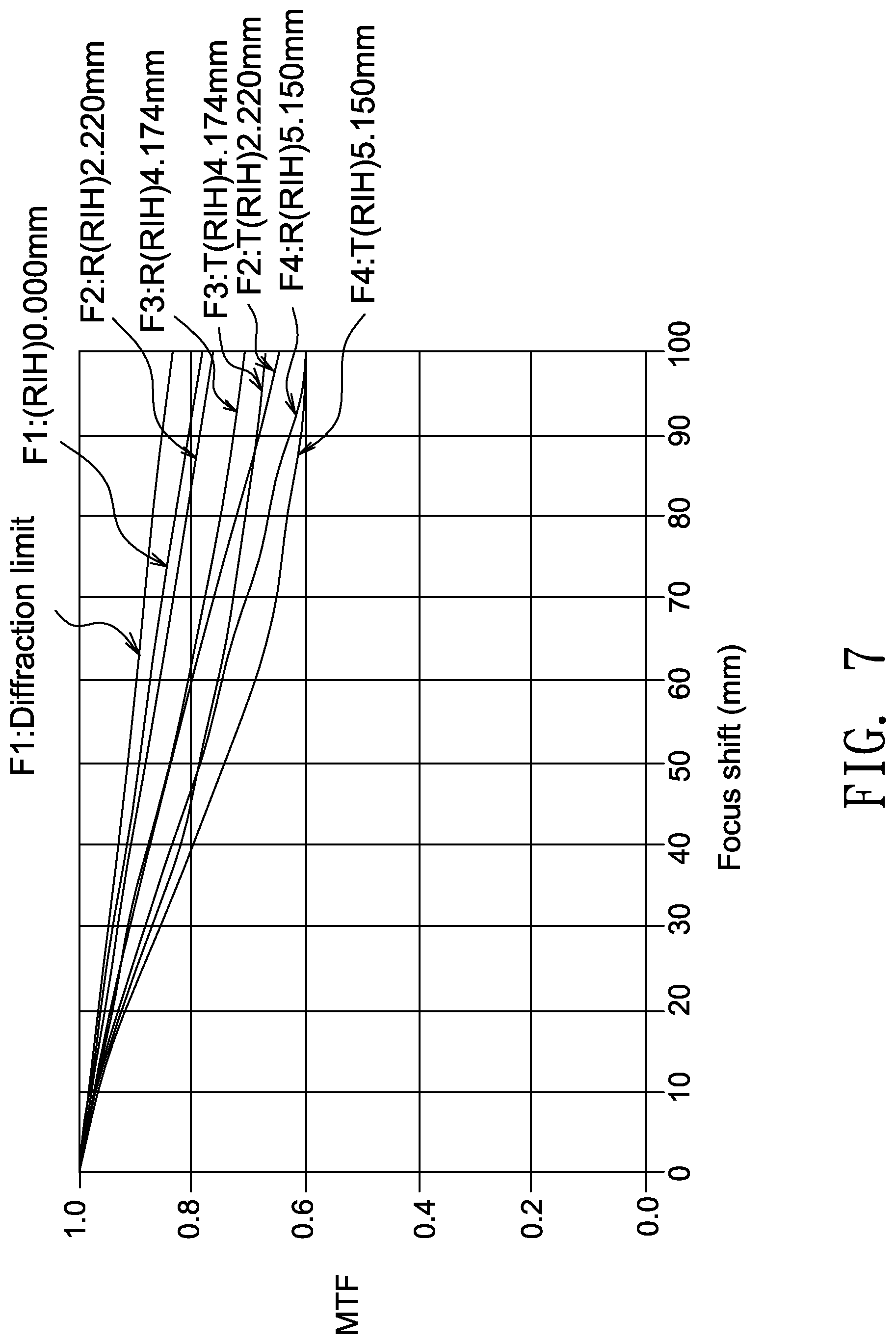
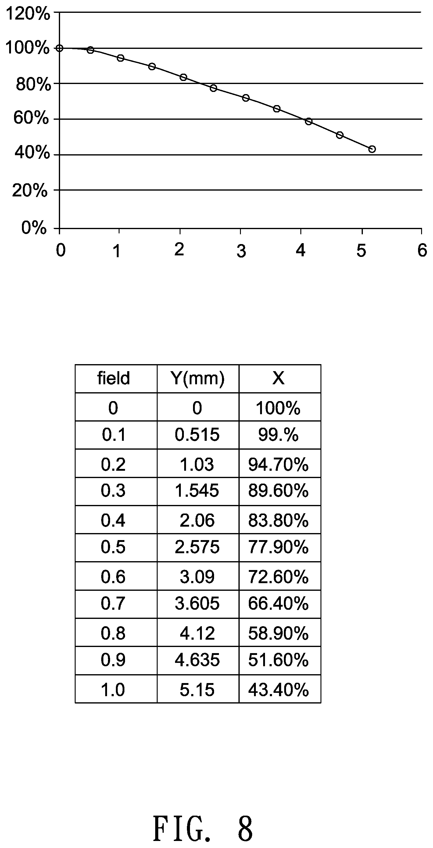
[0040] FIG. 5 shows a cross-sectional illustration of an optical lens 10b according to a second embodiment of the invention. In this embodiment, the refractive powers of the first lens L1 to the seventh lens L7 are negative, negative, positive, negative, positive, positive and negative, all the lenses L1-L7 are glass lenses, and the second lens L2 and the seventh lens L7 are aspheric lenses. In this embodiment, each aspheric lens is made from glass molding. In other embodiment, each aspheric lens may be made from plastic. Further, in this embodiment, the diameter of the surface S1 is 12 mm, and the diameter of the surface S14 is 10.23 mm. Detailed optical data and design parameters of the optical lens 10b are shown in Table 3 below.
TABLE-US-00003 TABLE 3 F/# = 2.2; LT = 22.91 (mm) FOV = 111.12 degrees; D/LT = 0.45 IMH25 = 2.22 (mm); IMH45 = 4.17 (mm) radius of curvature interval refractive Abbe surface (mm) (mm) index number object description S1 16.03 0.65 1.57 67.12 L1 (meniscus) S2 4.38 2.97 S3* -69.80 0.60 1.50 81.55 L2 (aspheric) S4* 6.84 1.29 S5 13.38 1.83 1.89 31.90 L3 (biconvex) S6 -15.20 2.27 S7 INF. 0.31 aperture stop S8 -37.71 0.60 1.77 25.00 L4 (biconcave) S9 4.91 1.57 1.74 51.45 L5 (biconvex) S10 -10.72 3.78 S11 9.48 3.12 1.70 55.54 L6 (biconvex) S12 -14.94 2.30 S13* 144.67 1.62 1.92 22.53 L7 (aspheric) S14* 11.49 0.35 S15 INF. 0.21 1.52 64.17 IR filter S16 INF. 0.20 S17 INF. 0.50 1.52 64.17 cover glass S18 INF. 0.83 S19 image plane
[0041] Table 4 lists aspheric coefficients and conic constant of each aspheric surface of the optical lens according to the second embodiment of the invention.
TABLE-US-00004 TABLE 4 S3 S4 S13 S14 k 0.000E+00 0.000E+00 0.000E+00 0.000E+00 A 1.310E-04 2.404E-04 -4.175E-03 -3.627E-03 B -5.333E-05 -8.036E-05 7.788E-06 8.272E-05 C 1.967E-06 1.394E-06 2.045E-07 -2.472E-06 D -3.797E-08 -1.623E-08 5.899E-09 2.899E-08
[0042] In the above Table 3, an interval of the surface S1 is a distance between the surface S1 and the surface S2 along the optical axis 12, an interval of the surface S2 is a distance between the surface S2 and the surface S3 along the optical axis 12, and an interval of the surface S18 is a distance between the surface S18 and the image plane 19 for visible light along the optical axis 12. An entrance pupil diameter of the optical lens 10b is greater than 2 mm, such as 2.25 mm in this embodiment. The optical lens 10b may have two lenses with an Abbe number of greater than 65.
[0043] In this embodiment, a ratio of an effective focal length of the optical lens to an effective focal length of the first lens group (front lens group) is 0.02, and a ratio of an effective focal length of the optical lens to an effective focal length of the second lens group (rear lens group) is 0.6.
[0044] FIG. 9 shows a cross-sectional illustration of an optical lens 10c according to a third embodiment of the invention. In this embodiment, the refractive powers of the first lens L1 to the seventh lens L7 are negative, negative, positive, positive, negative, positive and negative, all the lenses L1-L7 are glass lenses, and the first lens L1 and the seventh lens L7 are aspheric lenses. In this embodiment, each aspheric lens is made from glass molding. In other embodiment, each aspheric lens may be made from plastic. Further, in this embodiment, the diameter of the surface S1 is 12.2 mm, and the diameter of the surface S14 is 9.38 mm. Detailed optical data and design parameters of the optical lens 10c are shown in Table 5 below.
TABLE-US-00005 TABLE 5 F/# = 2.38; LT = 22.63 (mm) FOV = 110.28 degrees; D/LT = 0.41 IMH25 = 2.22 (mm); IMH45 = 4.14 (mm) radius of curvature interval refractive Abbe surface (mm) (mm) index number object description S1* 19.02 0.70 1.52 64.17 L1 (aspheric) S2* 3.39 5.25 S3 -5.19 1.92 2.00 19.32 L2 (meniscus) S4 -7.73 0.10 S5 8.68 1.24 1.85 30.05 L3 (biconvex) S6 -86.91 1.84 S7 INF. 0.67 aperture stop S8 11.22 1.61 1.50 81.61 L4 (biconvex) S9 -5.21 0.50 2.00 19.32 L5 (meniscus) S10 -10.72 1.60 S11 6.77 1.59 1.50 81.61 L6 (meniscus) S12 36.79 2.12 S13* -26.11 3.50 1.81 40.95 L7 (aspheric) S14* 338.02 0.64 S15 INF. 0.30 1.52 64.17 IR filter S16 INF. 0.50 S17 INF. 0.50 1.52 64.17 cover glass S18 INF. 0.50 S19 image plane
[0045] Table 6 lists aspheric coefficients and conic constant of each aspheric surface of the optical lens according to the third embodiment of the invention.
TABLE-US-00006 TABLE 6 S1 S2 S13 S14 k -3.482E+00 -4.525E-01 0.000E+00 0.000E+00 A 0.000E+00 0.000E+00 -3.557E-03 -2.025E-03 B 0.000E+00 0.000E+00 -3.027E-05 3.566E-05 C 0.000E+00 0.000E+00 1.425E-06 -7.208E-07
[0046] In the above Table 5, an interval of the surface S1 is a distance between the surface S1 and the surface S2 along the optical axis 12, an interval of the surface S2 is a distance between the surface S2 and the surface S3 along the optical axis 12, and an interval of the surface S18 is a distance between the surface S18 and the image plane 19 for visible light along the optical axis 12. An entrance pupil diameter of the optical lens 10c is greater than 2 mm, such as 2.09 mm in this embodiment. The optical lens 10c may have two lenses with an Abbe number of greater than 65.
[0047] In this embodiment, a ratio of an effective focal length of the optical lens to an effective focal length of the first lens group (front lens group) is 0.26, and a ratio of an effective focal length of the optical lens to an effective focal length of the second lens group (rear lens group) is 0.39.
[0048] FIG. 13 shows a cross-sectional illustration of an optical lens 10d according to a fourth embodiment of the invention. In this embodiment, the refractive powers of the first lens L1 to the seventh lens L7 are negative, negative, positive, negative, positive, positive and negative, all the lenses L1-L7 are glass lenses, and the seventh lens L7 is an aspheric lens. In this embodiment, each aspheric lens is made from glass molding. In other embodiment, each aspheric lens may be made from plastic. In this embodiment, the cover glass is omitted from the optical lens 10d to reduce fabrication costs. Further, in this embodiment, the diameter of the surface S1 is 12.22 mm, and the diameter of the surface S14 is 8.67 mm. Detailed optical data and design parameters of the optical lens 10d are shown in Table 7 below.
TABLE-US-00007 TABLE 7 F/# = 2.2; LT = 24.56 (mm) FOV = 107.79 degrees; D/LT = 0.35 IMH25 = 2.35 (mm); IMH45 = 4.26 (mm) radius of curvature interval refractive Abbe surface (mm) (mm) index number object description S1 17.72 1.01 1.49 70.42 L1 (meniscus) S2 4.25 3.26 S3 -16.51 0.65 1.49 70.42 L2 (biconcave) S4 6.00 0.61 S5 9.32 5.45 2.00 29.13 L3 (biconvex) S6 -18.85 0.10 S7 INF. 0.70 aperture stop S8 -8.93 0.71 1.89 23.78 L4 (biconcave) S9 12.62 2.36 1.62 63.40 L5 (biconvex) S10 -6.62 0.10 S11 7.87 5.64 1.59 68.62 L6 (biconvex) S12 -18.77 1.80 S13* -43.54 2.17 1.81 40.65 L7 (aspheric) S14* -150.55 1.10 S15 INF. 0.21 1.52 64.17 IR filter S16 INF. 3.14 S17 image plane
[0049] Table 8 lists aspheric coefficients and conic constant of each aspheric surface of the optical lens according to the fourth embodiment of the invention.
TABLE-US-00008 TABLE 8 S13 S14 k 0.000E+00 0.000E+00 A -1.748E-03 -1.111E-03 B -2.132E-06 1.753E-05 C 8.625E-08 3.119E-07 D 0.000E+00 3.681E-09
[0050] In the above Table 7, an interval of the surface S1 is a distance between the surface S1 and the surface S2 along the optical axis 12, an interval of the surface S2 is a distance between the surface S2 and the surface S3 along the optical axis 12, and an interval of the surface S16 is a distance between the surface S16 and the image plane 19 for visible light along the optical axis 12. An entrance pupil diameter of the optical lens 10d is greater than 2 mm, such as 2.45 mm in this embodiment. The optical lens 10d may have two lenses with an Abbe number of greater than 65.
[0051] In this embodiment, a ratio of an effective focal length of the optical lens to an effective focal length of the first lens group (front lens group) is 0.08, and a ratio of an effective focal length of the optical lens to an effective focal length of the second lens group (rear lens group) is 0.58.
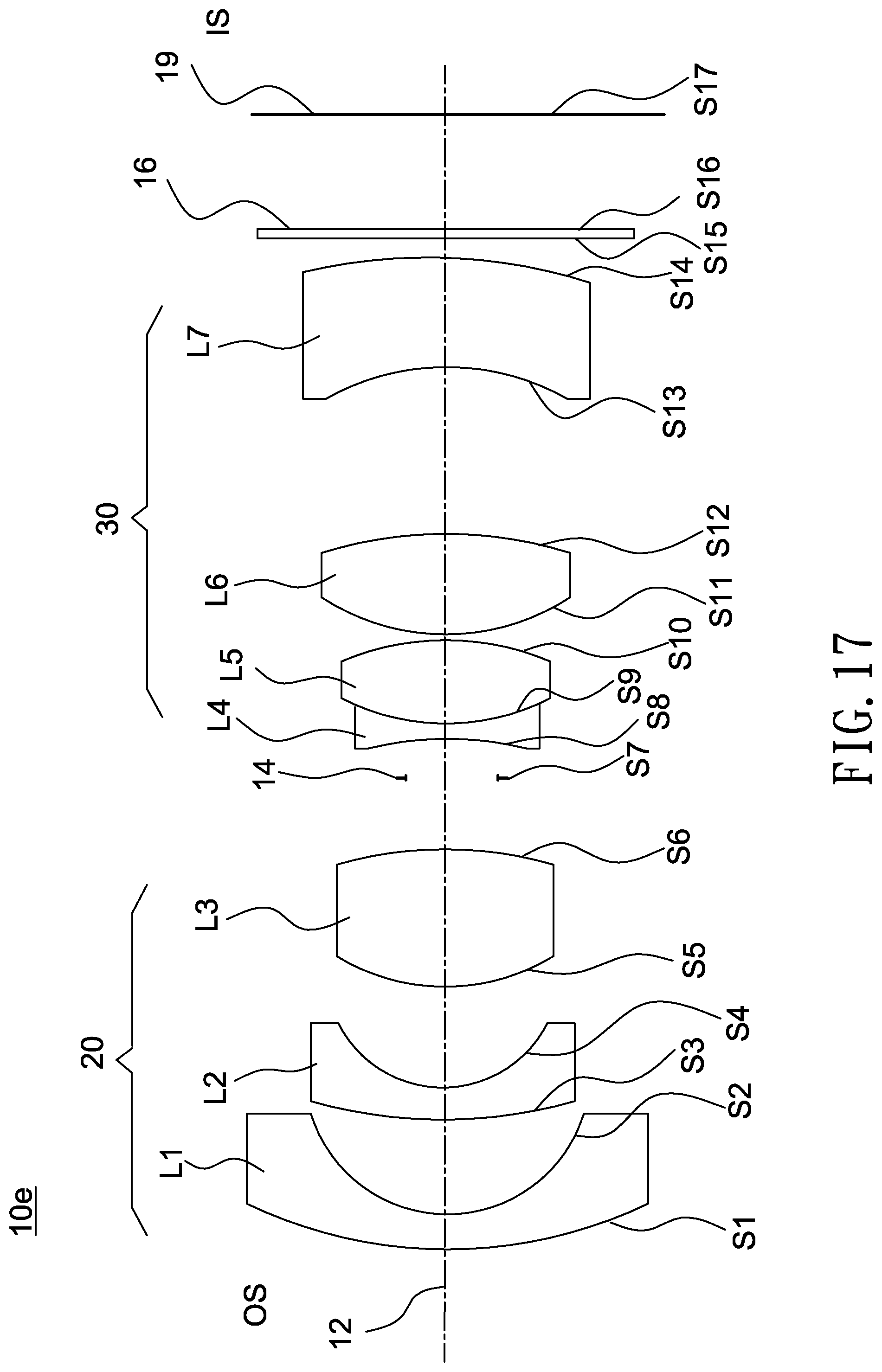
[0052] FIG. 17 shows a cross-sectional illustration of an optical lens 10e according to a fifth embodiment of the invention. In this embodiment, the refractive powers of the first lens L1 to the seventh lens L7 are negative, negative, positive, negative, positive, positive and negative, all the lenses L1-L7 are glass lenses, and the second lens L2 and the seventh lens L7 are aspheric lenses. In this embodiment, each aspheric lens is made from glass molding. In other embodiment, each aspheric lens may be made from plastic. The first lens L1, the second lens L2, and the third lens L3 form a first lens group 20 (such as a front lens group) with a negative refractive power, and the fourth lens L4, the fifth lens L5, the sixth lens L6 and the seventh lens L7 form a second lens group 30 (such as a rear lens group) with a positive refractive power. Further, in this embodiment, the diameter of the surface S1 is 13.6 mm, and the diameter of the surface S14 is 9.49 mm. Detailed optical data and design parameters of the optical lens 10e are shown in Table 9 below.
TABLE-US-00009 TABLE 9 F/# = 2.2; LT = 26.35 (mm) FOV = 107.38 degrees; D/LT = 0.36 IMH25 = 2.29 (mm); IMH45 = 4.26 (mm) radius of curvature interval refractive Abbe surface (mm) (mm) index number object description S1 23.82 0.74 1.49 70.44 L1 (meniscus) S2 5.07 2.83 S3* 22.87 0.81 1.51 64.03 L2 (aspheric) S4* 4.72 2.78 S5 16.63 3.23 2.00 29.13 L3 (biconvex) S6 -28.99 1.82 S7 INF. 1.08 aperture stop S8 -44.13 0.71 1.92 20.88 L4 (biconcave) S9 9.99 2.21 1.72 47.92 L5 (biconvex) S10 -10.40 0.10 S11 8.60 2.78 1.50 81.61 L6 (biconvex) S12 -20.44 4.44 S13* -43.75 2.83 1.81 40.65 L7 (aspheric) S14* -150.60 0.61 S15 INF. 0.21 1.52 64.17 IR filter S16 INF. 1.83 S17 image plane
[0053] Table 10 lists aspheric coefficients and conic constant of each aspheric surface of the optical lens according to the fifth embodiment of the invention.
TABLE-US-00010 TABLE 10 S3 S4 S13 S14 k 0.000E+00 0.000E+00 0.000E+00 0.000E+00 A -2.366E-04 -5.678E-04 -1.991E-03 -9.608E-04 B -3.138E-05 -7.104E-05 -1.970E-05 -1.672E-05 C 1.365E-06 7.803E-08 -1.613E-06 5.141E-07 D -2.477E-08 4.014E-08 3.834E-08 -3.066E-09 E 0.000E+00 -5.243E-09 0.000E+00 0.000E+00
[0054] In the above Table 9, an interval of the surface S1 is a distance between the surface S1 and the surface S2 along the optical axis 12, an interval of the surface S2 is a distance between the surface S2 and the surface S3 along the optical axis 12, and an interval of the surface S16 is a distance between the surface S16 and the image plane 19 for visible light along the optical axis 12. An entrance pupil diameter of the optical lens 10e is greater than 2 mm, such as 2.33 mm in this embodiment. The optical lens may have two lenses with an Abbe number of greater than 65.
[0055] In this embodiment, a ratio of an effective focal length of the optical lens to an effective focal length of the first lens group (front lens group) is -0.06, and a ratio of an effective focal length of the optical lens to an effective focal length of the second lens group (rear lens group) is 0.55.
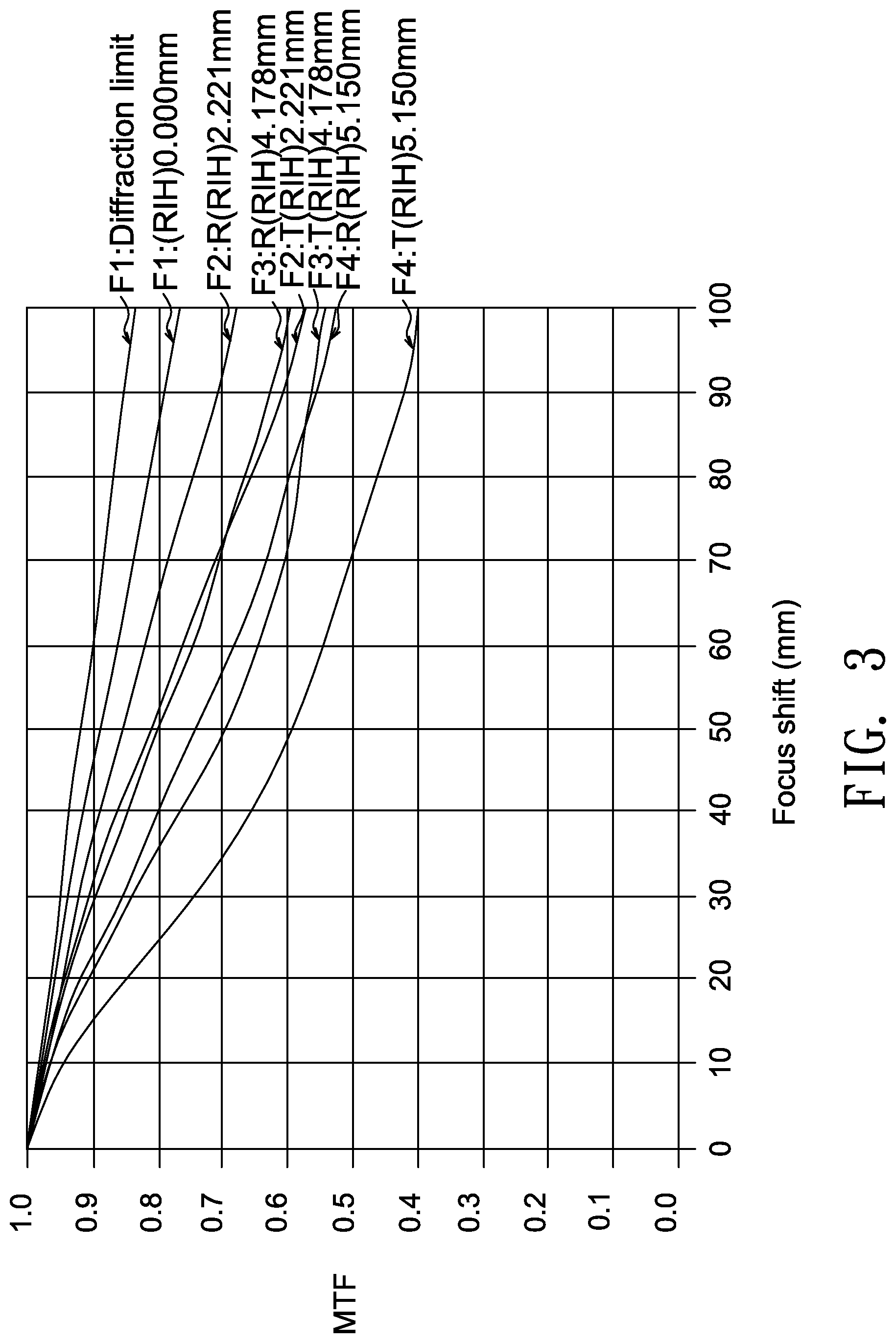
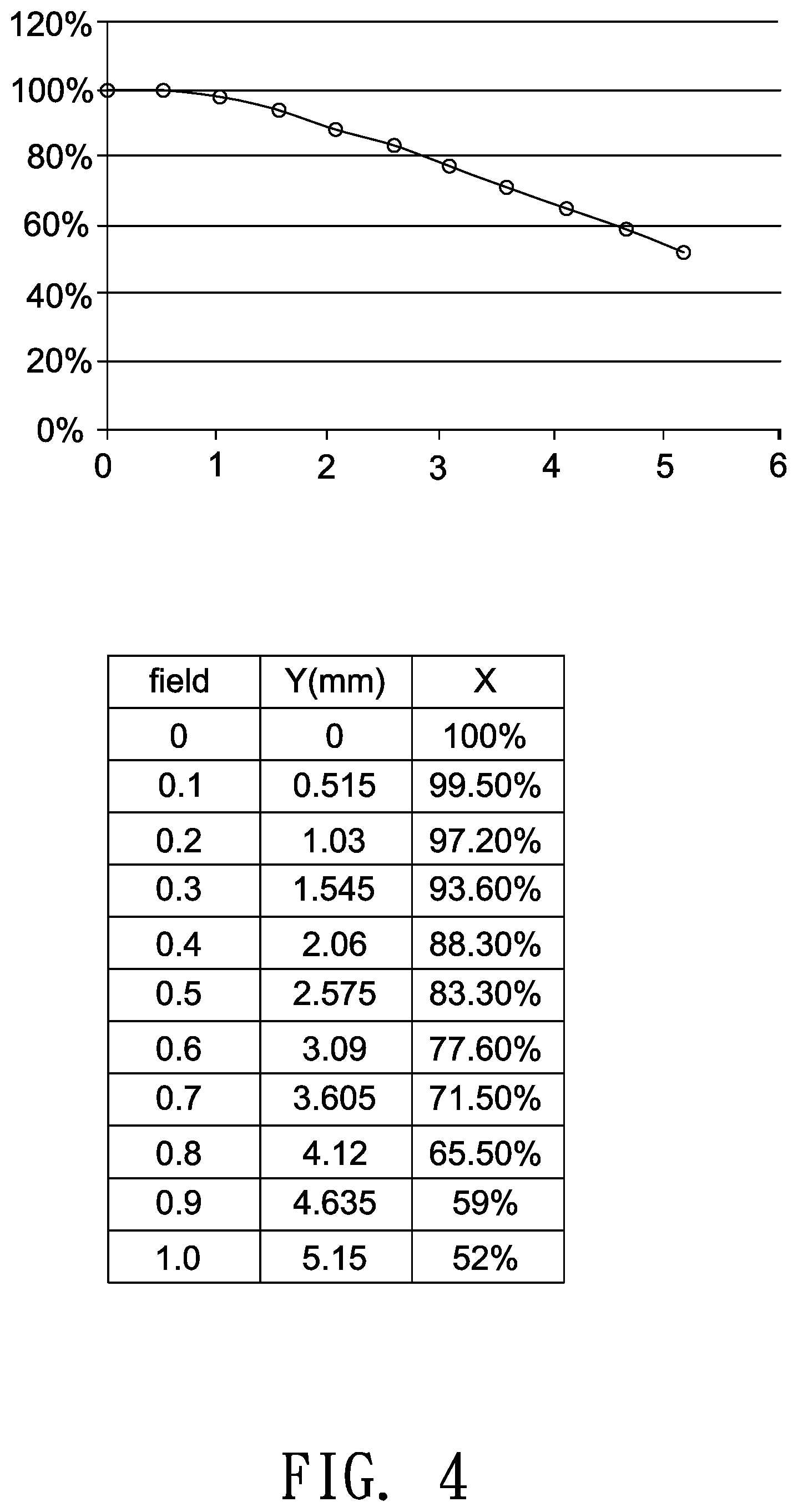
[0056] FIGS. 2-4, 6-8, 10-12, 14-16 and 18-20 respectively illustrate optical simulation results of the optical lenses 10a, 10b, 10c, 10d and 10e. FIGS. 2, 6, 10, 14 and 18 show ray fan plots for visible light of the optical lens 10a, 10b, 10c, 10d and 10e, respectively, where an abscissa of the plot represents entrance pupil positions, and an ordinate of the plot represents relative numerical values of positions on an image plane (such as the image plane S19) where main light beams are projected. FIGS. 3, 7, 11, 15 and 19 depict respective MTF curves of the optical lenses 10a, 10b, 10c, 10d and 10e. FIGS. 4, 8, 12, 16 and 20 depict respective relative illumination (RI) curves of the optical lenses 10a, 10b, 10c, 10d and 10e, where an image height on an image plane is divided into ten equal parts, and numerical values of relative illumination and ratios relative to the optical axis of each division point are shown in FIGS. 4, 8, 12, 16 and 20. The simulated results shown in FIGS. 2-4, 6-8, 10-12, 14-16 and 18-20 are within permitted ranges specified by the standard, which indicates the above embodiments of the optical lens 10a-10e may achieve good imaging quality.
[0057] According to the above embodiments, the optical lens may achieve good imaging quality, reduced fabrication costs and lighter weight and is favorable for miniaturization. Further, according to the above embodiments, the optical lens is allowed to operate at -40.degree. C. to 105.degree. C. and has a total lens number of 5 to 10. Therefore, the optical lens may achieve good imaging quality and resolution, lower fabrication costs, larger effective apertures, lighter weight and wide ranges of operating temperatures.
[0058] Though the embodiments of the invention and design parameters in the tables have been presented for purposes of illustration and description, they are not intended to be exhaustive or to limit the invention. Accordingly, many modifications and variations without departing from the spirit of the invention or essential characteristics thereof will be apparent to practitioners skilled in this art. It is intended that the scope of the invention be defined by the claims appended hereto and their equivalents in which all terms are meant in their broadest reasonable sense unless otherwise indicated.
* * * * *
D00000
D00001
D00002
D00003
D00004
D00005
D00006
D00007
D00008
D00009
D00010
D00011
D00012
D00013
D00014
D00015

D00016
D00017
D00018

D00019

D00020

XML
uspto.report is an independent third-party trademark research tool that is not affiliated, endorsed, or sponsored by the United States Patent and Trademark Office (USPTO) or any other governmental organization. The information provided by uspto.report is based on publicly available data at the time of writing and is intended for informational purposes only.
While we strive to provide accurate and up-to-date information, we do not guarantee the accuracy, completeness, reliability, or suitability of the information displayed on this site. The use of this site is at your own risk. Any reliance you place on such information is therefore strictly at your own risk.
All official trademark data, including owner information, should be verified by visiting the official USPTO website at www.uspto.gov. This site is not intended to replace professional legal advice and should not be used as a substitute for consulting with a legal professional who is knowledgeable about trademark law.