Travelling Wave Based Method For Locating A Fault In A Transmission Line And Device Therefor
NAIDU; Obbalareddi Demudu ; et al.
U.S. patent application number 16/474054 was filed with the patent office on 2019-12-05 for travelling wave based method for locating a fault in a transmission line and device therefor. The applicant listed for this patent is ABB Schweiz AG. Invention is credited to Neethu GEORGE, Obbalareddi Demudu NAIDU, Sachin SRIVASTAVA.
| Application Number | 20190369156 16/474054 |
| Document ID | / |
| Family ID | 58707964 |
| Filed Date | 2019-12-05 |


| United States Patent Application | 20190369156 |
| Kind Code | A1 |
| NAIDU; Obbalareddi Demudu ; et al. | December 5, 2019 |
TRAVELLING WAVE BASED METHOD FOR LOCATING A FAULT IN A TRANSMISSION LINE AND DEVICE THEREFOR
Abstract
The invention provides an Intelligent Electronic Device (IED) and a method for locating a fault in a power transmission line with the IED. The method comprises measuring arrival times of a first, second and third peak of a travelling wave, using measurements obtained with one or more measurement equipment connected with the power transmission line. The method further comprises generating two or more initial estimates for the location of the fault, estimating time of initiation of the travelling wave, and estimating an arrival time of the third peak. The estimated arrival time of the third peak is compared with the measured arrival time of the third peak, to select an initial estimate of the two or more initial estimates as the location of the fault.
| Inventors: | NAIDU; Obbalareddi Demudu; (Bengaluru, IN) ; GEORGE; Neethu; (Kottayam, IN) ; SRIVASTAVA; Sachin; (Bengaluru, IN) | ||||||||||
| Applicant: |
|
||||||||||
|---|---|---|---|---|---|---|---|---|---|---|---|
| Family ID: | 58707964 | ||||||||||
| Appl. No.: | 16/474054 | ||||||||||
| Filed: | April 20, 2017 | ||||||||||
| PCT Filed: | April 20, 2017 | ||||||||||
| PCT NO: | PCT/IB2017/052270 | ||||||||||
| 371 Date: | June 26, 2019 |
| Current U.S. Class: | 1/1 |
| Current CPC Class: | G01R 31/085 20130101 |
| International Class: | G01R 31/08 20060101 G01R031/08 |
Foreign Application Data
| Date | Code | Application Number |
|---|---|---|
| Dec 28, 2016 | IN | 201641044552 |
Claims
1. A method for locating a fault in a power transmission line with an Intelligent Electronic Device (IED), wherein the IED is connected with one or more measurement equipment connected with the power transmission line, the IED: measuring an arrival time of a first peak, a second peak and a third peak of a travelling wave detected from one or more measurements of electrical parameters of the power transmission line, wherein the one or more measurements are obtained with the one or more measurement equipment; generating two or more initial estimates of the location of the fault, wherein a first initial estimate of the two or more initial estimates is generated based on the arrival time of the first peak, the arrival time of the second peak, and a velocity of propagation of the travelling wave, and a second initial estimate of the two or more initial estimates is generated based on the arrival time of the first peak, the arrival time of the second peak, the velocity of propagation of the travelling wave and length of the power transmission line; estimating of time of initiation of the travelling wave based on one of: the arrival time of the first peak, the first initial estimate and the velocity of propagation of the travelling wave, the arrival time of the second peak, the second initial estimate, and the velocity of propagation of the travelling wave, and the arrival time of the second peak, the second initial estimate, the velocity of propagation of the travelling wave and the length of the power transmission line; estimating an arrival time of the third peak based on one of: the first initial estimate, the estimate of time of initiation of the travelling wave, and the velocity of propagation of the travelling wave, the second initial estimate, the estimate of time of initiation of the travelling wave, and the velocity of propagation of the travelling wave, and the second initial estimate, the estimate of time of initiation of the travelling wave, the velocity of propagation of the travelling wave and the length of the power transmission line; and selecting one of the first initial estimate and the second initial estimate as the location of fault, based on a comparison of the estimated arrival time of the third peak with the measured arrival time of the third peak.
2. The method as claimed in claim 1, wherein the arrival times are measured at the IED based on one of: the one or more measurements recorded with the IED, and the one or more measurements received at the IED.
3. The method as claimed in claim 1, wherein the first initial estimate is selected as the location of the fault if the difference between the estimated arrival time of the third peak and the measured arrival time of the third peak is less than a threshold value.
4. The method as claimed in claim 1, wherein the second initial estimate is selected as the location of the fault if the difference between the estimated arrival time of the third peak and the measured arrival time of the third peak is greater than a threshold value.
5. The method as claimed in claim 1, wherein the estimated arrival time of the third peak is generated by identifying distance corresponding to the third peak.
6. The method as claimed in claim 1, wherein a first substation is connected at a first end of the power transmission line and a second substation is connected at a second end of the power transmission line, and the IED operates at the first end.
7. An intelligent electronic device for locating a fault in a power transmission line, the intelligent electronic device comprising: a travelling wave module for measuring arrival time of a first peak, a second peak and a third peak of a travelling wave detected from one or more measurements of electrical parameters of the power transmission line, wherein the one or more measurements are obtained with the one or more measurement equipment; and an initial estimate module for generating two or more initial estimates of the location of the fault, wherein a first initial estimate of the two or more initial estimates is generated based on the arrival time of the first peak, the arrival time of the second peak, and a velocity of propagation of the travelling wave, and a second initial estimate of the two or more initial estimates is generated based on the arrival time of the first peak, the arrival time of the second peak, the velocity of propagation of the travelling wave and length of the power transmission line; a time estimation module for: estimating of time of initiation of the travelling wave based on one of: the arrival time of the first peak, the first initial estimate and the velocity of propagation of the travelling wave, the arrival time of the second peak, the second initial estimate, and the velocity of propagation of the travelling wave, and the arrival time of the second peak, the second initial estimate, the velocity of propagation of the travelling wave and the length of the power transmission line; and estimating an arrival time of the third peak based on one of: the first initial estimate, the estimate of time of initiation of the travelling wave, and the velocity of propagation of the travelling wave, the second initial estimate, the estimate of time of initiation of the travelling wave, and the velocity of propagation of the travelling wave, and the second initial estimate, the estimate of time of initiation of the travelling wave, the velocity of propagation of the travelling wave and the length of the power transmission line; and a fault location module for selecting one of the first initial estimate and the second initial estimate as the location of fault, based on a comparison of the estimated arrival time of the third peak with the measured arrival time of the third peak.
8. The IED as claimed in claim 7, wherein the traveling wave module detects the traveling wave from the one or more measurements of electrical parameters of the power transmission line received from the one or more measurement equipment.
9. The IED as claimed in claim 7, wherein the IED receives the one or more measurements of the electrical parameters from the one or more measurement equipment over a communication channel.
Description
FIELD OF THE INVENTION
[0001] The present invention relates generally to locating faults in power transmission lines, and more specifically to travelling wave based fault location.
BACKGROUND OF THE INVENTION
[0002] Accurate fault location in transmission lines is very important for maintenance crew to reach the faulted location and undertake repair quickly. Accurate identification of fault location improve the reliability, availability and save the revenue loss for the utilities.
[0003] Fault location methods are classified into two categories based on the availability of input quantities, namely single ended and two ended. Additionally, according to fault location principle fault location methods are categorized as 1) Impedance based method and 2) Traveling wave based method Impedance based fault location methods have poor accuracies due to uncertainties in the measurements, filtering techniques and dynamic system conditions.
[0004] A travelling wave is an electromagnetic transient travelling across the power circuit and equipment for any sudden change in electrical parameter of the line. For example, faults in a transmission network is one such scenario. These travelling waves follow the electromagnetic parameters of the equipment, which remain constant with respect to system conditions. Hence, travelling wave based methods are more accurate as they are not affected by steady state and dynamic system conditions.
[0005] Fault location using traveling wave is estimated by multiplying the time difference between initial traveling waves and/or its reflection at the point and propagation velocity. Communication based travelling wave methods are considered more accurate and reliable. However, the complexity of establishing communication channel is high and reliability of the method depends on the quality of communication. In addition, accurate GPS synchronization at both side is mandatory for communication based methods. This further impacts the accuracy and complexity of fault locator (or IED). Hence, the single ended method is preferred by the most utilities worldwide for fault location.
[0006] Travelling waves can be generated by any disturbance across the power transmission line. According to the location of the fault, there is a change in the sequence of reflections/refractions arriving at a known point in the line. Identifying source of traveling wave reflections/refractions, i.e. if the reflection is from the fault or from a known point in the line (e.g. far end bus) is a major challenge in single ended travelling wave based methods. Once the sequence of wave is identified, then fault location can be calculated based on the arrival times.
SUMMARY OF THE INVENTION
[0007] Various aspects of the present invention provide an Intelligent Electronic Device (IED) and a method for locating a fault in a power transmission line. The method of the present invention can be used for different types of power transmission lines such as overhead lines, underground cables, mixed lines having overhead lines connected with underground cables as well as different possible combinations of mixed lines such as overhead line connected with underground cable and following with overhead line or underground cable connected with overhead line and following with underground cables etc. In an embodiment of the present invention, the power transmission line connects two substations, wherein a first substation is at a first end of the power transmission line and a second substation is at a second end of the power transmission line.
[0008] In accordance with various aspects, the method is performed with the IED. The IED is connected with one or more measurement equipment connected with the power transmission line. For example, the measurement equipment can include a current transformer, a potential transformer, a sensor-based measurement equipment (e.g. Rogowski coils, non-conventional instrument transformers etc.) and/or the like, which provides a signal/measurement corresponding to current, voltage or other information as sensed from the power transmission line. For example, a current transformer provides single/multiple phase current signal and a potential transformer can provide single/multiple phase voltage signal to the IED. The IED may alternately (or additionally) receive measurements from the measurement equipment or other terminals of the power system over a communication channel.
[0009] In an embodiment the IED receives a signal(s) from the measurement equipment, and obtain measurements therefrom. In another embodiment, the measurement equipment publishes the measurements over a bus (e.g. process bus), and the IED (e.g. subscribed to receive data from such bus) receives the measurements over the bus.
[0010] A travelling wave(s) may be generated due to a fault in the transmission line. The travelling wave may be detected from one or more measurements of electrical parameters (e.g. current/voltage) of the power transmission line, wherein the one or more measurements are obtained with the one or more measurement equipment. Such detection may happen at the IED or at another terminal of the power transmission line. For example, a module(s) to detect travelling wave and parameters thereof, may be provided in another IED or power line device. In an embodiment, the IED has a travelling wave module to detect the travelling wave and parameters thereof (e.g. arrival times of first peak, second peak, third peak etc.). In another embodiment, the travelling wave module receives the travelling wave parameters over the bus (e.g. the IED can be subscribed to receive data published over a process bus).
[0011] In accordance with the method, actual time of arrival of a first peak, a second peak and a third peak of the travelling wave are measured. The measurement of the actual time of arrival of the first peak, the second peak and the third peak, or other travelling wave parameters can be performed with the IED, or with another terminal and then transmitted to the IED. In either case, the measured parameters are stored at the IED (e.g. in a memory).
[0012] The method further includes generating two or more initial estimates of the location of the fault. The two or more initial estimates can be performed with an initial estimate module of the IED. In an embodiment, a first initial estimate (d1) of the two or more estimates is generated based on: [0013] the arrival time of the first peak, [0014] the arrival time of the second peak, and [0015] a velocity of propagation of the travelling wave.
[0016] Further, a second initial estimate (d2) of the two or more estimates is generated based on: [0017] the arrival time of the first peak, [0018] the arrival time of the second peak, [0019] the velocity of propagation of the travelling wave, and [0020] length of the power transmission line.
[0021] The method also includes estimating a time of initiation (t0_estimate) of the travelling wave. A time estimate module of the IED can generate t0_estimate. t0_estimate is generated based on the arrival time of one of the first peak and the second peak, one of the two initial estimates (d1 or d2 respectively), and the velocity of propagation of the travelling wave. Optionally length of the power transmission line may be used for generating t0_estimate.
[0022] In addition, the method includes estimating an arrival time of the third peak (t3_estimate) based on one of the first initial estimate (d1) and the second initial estimate (d2), the estimate of time of initiation of the travelling wave, and the velocity of propagation of the travelling wave. Optionally length of the power transmission line may be used for generating t3_estimate. The time estimate module of the IED generates t3_estimate. t3_estimate can be generated by identifying distance corresponding to the third peak.
[0023] Thereafter, the method includes determining the location of the fault based on a comparison of the estimated arrival time of the third peak with the measured arrival time of the third peak. A fault location module of the IED determines the location of the fault in accordance with an embodiment of the invention.
[0024] In one embodiment, the difference between the estimated and measured arrival time of the third peak is compared with a threshold value(s) (e.g. with the IED). There could be multiple threshold values with the IED for comparison between the estimated and actual values of the arrival time of the third peak. In an embodiment, the first initial estimate is selected as the location of the fault if the difference between the estimate of arrival time of the third peak is less than the actual (recorded) time of arrival of the third peak by a value less than the threshold value. In accordance with the embodiment, the second initial estimate is selected as the location of the fault if the difference is greater than the threshold value.
[0025] In an embodiment, the IED communicates measurements with a server (e.g. cloud server). For example, there could be a communication channel between the IED and the server. In such a case, the server can perform the processing and calculate the fault location and publish it across the subscribers (including the IED).
BRIEF DESCRIPTION OF DRAWINGS
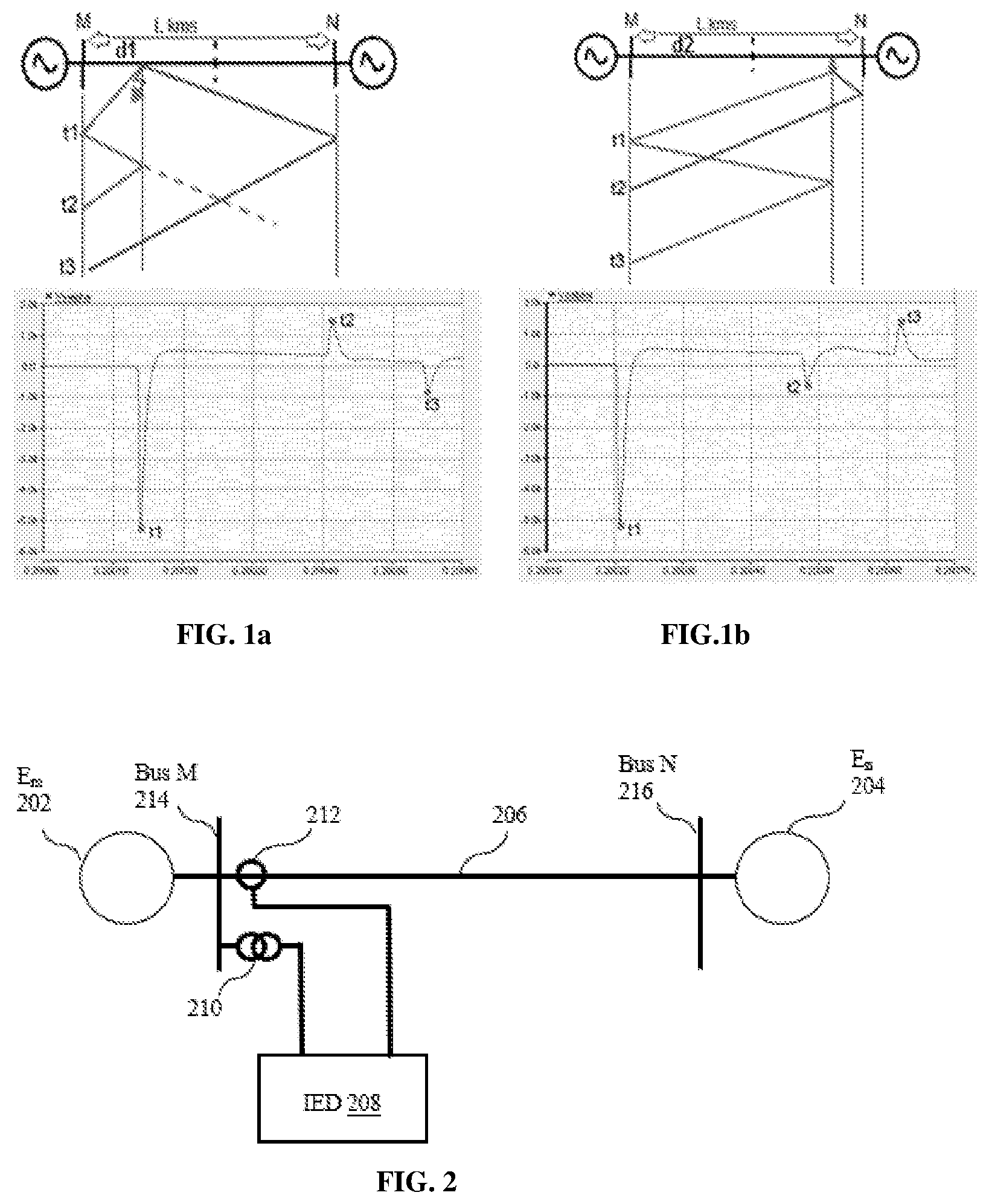
[0026] FIG. 1a and FIG. 1b show example Bewley Lattice diagrams.
[0027] FIG. 2 is a simplified diagram of a system for locating a fault in a power transmission line, in accordance with an embodiment of the invention.
[0028] FIG. 3 is a simplified diagram showing a fault in the power transmission line, in accordance with an embodiment of the invention.
[0029] FIG. 4 is a simplified block diagram of an intelligent electronic device for locating the fault in the power transmission line, in accordance with an embodiment of the invention.
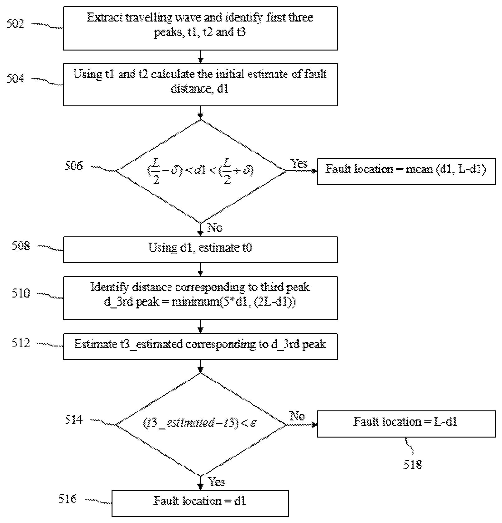
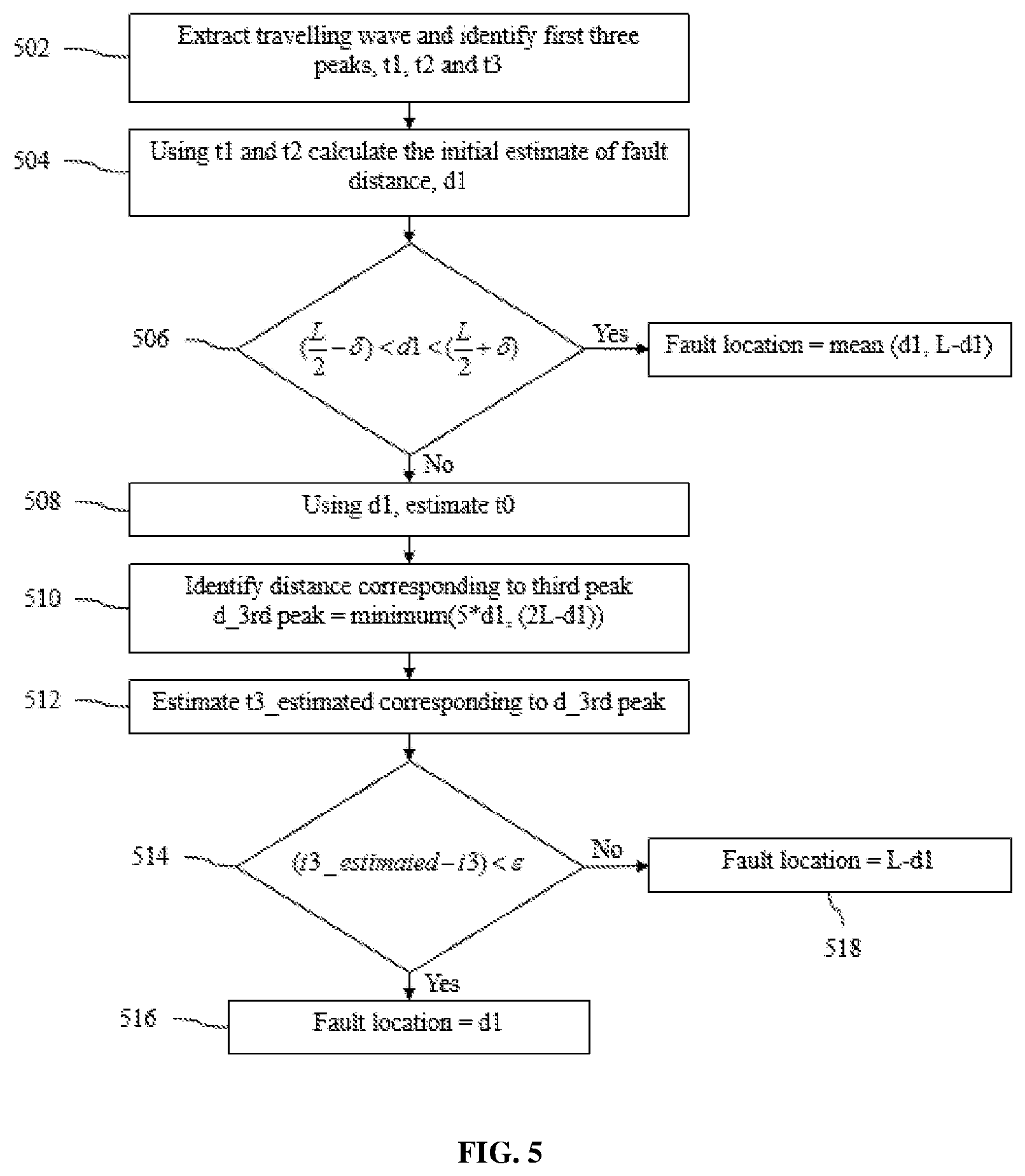
[0030] FIG. 5 is a flowchart of a method for locating the fault in the power transmission line, in accordance with an embodiment of the invention.
DETAILED DESCRIPTION
[0031] Faults in transmission lines occur because of several reasons. A travelling wave(s) may be generated due to a fault in a power transmission line. Depending on the location of the fault, a particular peak (e.g. second peak) of the travelling wave can be of a reflection from the fault point, or from a known point in the line. The location of the fault can be calculated based on second peak information, i.e. if it is known whether the second is coming from fault point or far end bus (or other known point in the line such as junction of an overhead line and cable section).
[0032] Referring to FIG. 2, a first substation (E.sub.m 202) can be at one end (first) of the power transmission line and a second substation (E.sub.n 204) at another end (second) of the power transmission line (206). Further, as shown, an Intelligent Electronic Device (208) may be operating at bus M (214). The IED can be connected with one or more measurement equipment. For example, the IED gets the voltage and current measurement input from the potential transformer (PT 210) and current transformer (CT 212) respectively, and such information can be stored in Disturbance Fault Recorder (DFR). In an embodiment, a voltage/current travelling wave is extracted from the information stored in the DFR. The extracted travelling wave is then used to estimate the fault location. Such travelling wave detection (and detection of parameters thereof) may be performed in another IED or power line device, and transmitted to the IED (e.g. over a bus on which the IED is subscribed).
[0033] The major challenge in calculation of fault location, using such a single ended travelling wave system (shown in FIG. 2) is identifying source of traveling wave reflections/refractions, i.e. if the reflection is from the fault or far end bus (or other known point on the power transmission line).
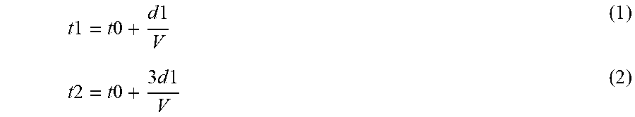
[0034] FIG. 1(a) shows Bewley Lattice diagram for case, when the fault has occurred in a first half of the power transmission line. Here, the power transmission line is an overhead line (OHL). In this case the first peak as well as the second peak comes from the fault point. For a fault at `d1` km from terminal M, where L is the length of the power transmission line (shown in FIG. 3), first and second peak arrival times can be expressed as in equation (1) and (2) below:
t 1 = t 0 + d 1 V ( 1 ) t 2 = t 0 + 3 d 1 V ( 2 ) ##EQU00001##
where, [0035] v is propagation velocity of transmission line (velocity of propagation of the travelling wave in the line), [0036] t0 is fault initiated time (time of initiation of the travelling wave), [0037] t1 is first peak arrival time (arrival time of first peak of the travelling wave), [0038] t2 is second peak arrival time (arrival time of first peak of the travelling wave), [0039] d1 is first estimate of fault location (e.g. corresponding to a fault in first half of the line), [0040] 3d1 is used in equation (2) because second peak traveled 3d1 distance (as can be seen from FIG. 1(a), three times the distance d1 has to be covered for the second peak to reach bus M).
[0041] Solving both the equations, fault location for fault in first half is given by equation (3):
d 1 = ( t 2 - t 1 ) .times. V 2 ( 3 ) ##EQU00002##
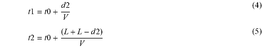
[0042] The Bewley Lattice diagram of FIG. 1(b) shows the case when fault has occurred in second half of the line. In this case, the first peak corresponds to reflection from fault point and the second peak corresponds to reflection from far end bus. For a fault at `d2` km from terminal M, first and second peak arrival times can be expressed as in equation (4) and (5) below.
t 1 = t 0 + d 2 V ( 4 ) t 2 = t 0 + ( L + L - d 2 ) V ( 5 ) ##EQU00003##
[0043] Solving both the equations, fault location in second half is given by,
d 2 = L - ( t 2 - t 1 ) .times. V 2 ( 6 ) ##EQU00004##
[0044] Hence, to select the actual fault location from the two initial estimates calculated using equation (3) and (6), we need to know if the fault has occurred in the first half or the second half of the line.
[0045] The present invention solves the challenge of identification of the actual fault location from the two possible location estimates, by using the third peak arrival time information.
[0046] The present invention provides an IED (300) for locating the fault in the power transmission line. The IED can operate at bus M (214) (such as IED 208 shown in FIG. 2), bus N (216) or other known point of the power transmission line. The IED can communicate with one or more measurement equipment (such as voltage transformer 210, current transformer 212 etc. over a bus) for obtaining measurements of the power transmission line. The IED can have one or multiple modules for locating the fault in the power transmission line.
[0047] In the embodiment shown in FIG. 4, the IED (300) has a travelling wave module (302), an initial estimate module (304), a time estimate module (306) and a fault location module (308).
[0048] Referring to FIG. 5, which is a flowchart of the method of locating the fault, in accordance with an embodiment.
[0049] Let the time of first peak of the travelling wave measured at M be t1, the time of second peak of the travelling wave measured at M be t2 and the time of third peak of the travelling wave measured at M be t3_actual. The arrival times may be measured with the travelling wave module, or received from another terminal, and recorded with the travelling wave module at 502.
[0050] Two or more initial estimates of fault location are generated at 504. Such initial estimates are generated with initial estimate module of the IED. In one embodiment, two initial estimates of fault location, d1 (first initial estimate) and d2 (second initial estimate), are obtained using equations (3) and (6). Equation (3) gives a fault location estimate, d1, in the first half of the line. Similarly, equation (6) gives the fault location estimate, d2, in the second half of the line. This may be irrespective of the actual fault location being in first half or second half.
[0051] In cases where the initial fault estimates d1 and d2, is very close to the midpoint of the line, the actual fault location can be calculated as average of d1 and d2. Such determination may be optionally made at 506 by comparing d1 with
( L 2 - .delta. ) and ( L 2 + .delta. ) . ##EQU00005##
This can improve accuracy for faults close to the midpoint of the transmission line.
[0052] At 508, an estimate of fault initiated time (or time of initiation of travelling wave), t0 is obtained. Such estimation can be performed with the time estimate module of the IED. The estimated fault location (d1) can be substituted in equation (1) to calculate fault initiated time (t0). Alternately, d2 can be substituted in equation (5) to obtain t0. Optionally length of the power transmission line may be used for generating t0 estimate.
[0053] Using the known fault location estimate (d1) and fault initiated time (t0), the distance corresponding to the third peak, `d_3 rd peak` can be calculated using equation (7) at 510. Minimum is used in equation (7) because 3rd peak can also come from fault point or reflection from far end bus.
d_3rd peak=minimum(5*d1,(2L-d1)) (7)
[0054] In place of d1, d2 may be used for identifying distance corresponding to the third peak.
[0055] At 512, an estimate of arrival time of the third peak (t3_estimated) is generated. This estimation can be performed with the time estimate module of the IED. t3_estimated can be estimated using equation (8).
t 3 _estimated = t 0 + d_ 3 rdpeak V ( 8 ) ##EQU00006##
[0056] At 514, measured and estimated third peak arrival time are compared. This comparison can be performed with the fault location module. This step compares the actual measured third peak time `t3_actual` to the estimated third peak time `t3_estimated`.
[0057] If the difference between t3_estimated and t3_actual measured from the travelling wave is less than a threshold value (with the IED), the actual fault distance is d1 (516). The threshold may be based on sampling frequency of the IED. For example, 2 microseconds for 1 MHz sampling may be set as threshold. If the difference is greater than the threshold, it means the initial estimate d1 is not the actual fault location. Instead d2 is the actual fault location (518). It is possible to have a zero threshold value, for such comparison.
[0058] Thus the present invention provides a solution for accurately identifying the actual fault location with actual arrival time information of the first, second and third peaks in a travelling wave. Third peak in the travelling wave is available for faults in transmission lines, even when the fault inception angle is zero, thereby leading to accurate fault location. The identified location information can be communicated to maintenance crew to reach the faulted location and undertake repair quickly.
* * * * *
D00000
D00001
D00002
D00003
XML
uspto.report is an independent third-party trademark research tool that is not affiliated, endorsed, or sponsored by the United States Patent and Trademark Office (USPTO) or any other governmental organization. The information provided by uspto.report is based on publicly available data at the time of writing and is intended for informational purposes only.
While we strive to provide accurate and up-to-date information, we do not guarantee the accuracy, completeness, reliability, or suitability of the information displayed on this site. The use of this site is at your own risk. Any reliance you place on such information is therefore strictly at your own risk.
All official trademark data, including owner information, should be verified by visiting the official USPTO website at www.uspto.gov. This site is not intended to replace professional legal advice and should not be used as a substitute for consulting with a legal professional who is knowledgeable about trademark law.