Dehumidifier
Yoon; Chul Min
U.S. patent application number 16/480920 was filed with the patent office on 2019-12-05 for dehumidifier. The applicant listed for this patent is WINIX INC.. Invention is credited to Chul Min Yoon.
| Application Number | 20190368771 16/480920 |
| Document ID | / |
| Family ID | 63370751 |
| Filed Date | 2019-12-05 |

| United States Patent Application | 20190368771 |
| Kind Code | A1 |
| Yoon; Chul Min | December 5, 2019 |
DEHUMIDIFIER
Abstract
A dehumidifier according to an embodiment comprises: a main body which suctions air through a suction port and discharges same through a discharge port; a heat exchange part which removes moisture in the air suctioned through the suction port and comprises an evaporator and a condenser; a blowing part disposed between the suction port and the heat exchange part and guides the air from the suction port to the evaporator of the heat exchange part; and an accommodation part disposed under the evaporator and accommodating dehumidified water generated by the evaporator. The evaporator is obliquely disposed with respect to the longitudinal axis of the main body and toward the accommodation part, and the dehumidified water condensed by means of the evaporator can be dropped into the accommodation part by gravity.
| Inventors: | Yoon; Chul Min; (Siheung, KR) | ||||||||||
| Applicant: |
|
||||||||||
|---|---|---|---|---|---|---|---|---|---|---|---|
| Family ID: | 63370751 | ||||||||||
| Appl. No.: | 16/480920 | ||||||||||
| Filed: | March 2, 2017 | ||||||||||
| PCT Filed: | March 2, 2017 | ||||||||||
| PCT NO: | PCT/KR2017/002241 | ||||||||||
| 371 Date: | July 25, 2019 |
| Current U.S. Class: | 1/1 |
| Current CPC Class: | F24F 13/20 20130101; F24F 2003/1452 20130101; F24F 13/24 20130101; F24F 2003/1446 20130101; F24F 2110/10 20180101; F24F 13/30 20130101; F24F 13/082 20130101; F24F 2110/20 20180101; F24F 13/22 20130101; F24F 3/1405 20130101; F24F 1/0358 20190201; F24F 13/222 20130101 |
| International Class: | F24F 13/08 20060101 F24F013/08; F24F 13/20 20060101 F24F013/20 |
Foreign Application Data
| Date | Code | Application Number |
|---|---|---|
| Feb 28, 2017 | KR | 10-2017-0026467 |
Claims
1. A dehumidifier comprising: a body configured to suction air through an inlet and discharge the air through an outlet; a heat exchanger comprising an evaporator and a condenser and configured to remove moisture in the air suctioned through the inlet; a blower disposed between the inlet and the heat exchanger to guide the air from the inlet to the evaporator of the heat exchanger; and an accommodator disposed under the evaporator to accept dehumidification water generated in the evaporator, wherein the evaporator is obliquely disposed based on a longitudinal axis of the body to face the accommodator, so that the dehumidification water condensed in the evaporator falls into the accommodator by force of gravity.
2. The dehumidifier of claim 1, wherein the condenser is obliquely disposed above the evaporator based on the longitudinal axis of the body to face an upper surface of the body and the air passing the evaporator rises toward the condenser.
3. The dehumidifier of claim 2, further comprising: a guide disposed between the evaporator and the condenser, wherein the guide is configured to extend from an upper end of the inlet toward an inside of the body and formed in a shape that covers the evaporator and the blower and the air passing the evaporator is guided by the guide to the condenser.
4. The dehumidifier of claim 3, wherein a lower end of the guide is bent in a direction away from the evaporator or in a direction toward the condenser.
5. The dehumidifier of claim 4, wherein the blower is obliquely disposed based on the longitudinal axis of the body to face the accommodator.
6. The dehumidifier of claim 5, wherein the inlet is formed in a rear surface of the body, the outlet is formed in a top surface of the body, the blower allows the air suctioned through the inlet to travel toward the evaporator, and the air passing the evaporator passes the condenser to be discharged through the outlet to an outside.
7. A dehumidifier comprising: a body configured to suction air through an inlet and discharge the air through an outlet; an accommodator disposed in the body to accept dehumidification water; a blower disposed above the accommodator to guide the air suctioned through the inlet toward the accommodator; an evaporator disposed between the blower and the accommodator and configured to cool the suctioned air to condense moisture in the air; and a condenser configured to heat the air having passed the evaporator while condensing a refrigerant used in the dehumidifier.
8. The dehumidifier of claim 7, wherein the evaporator and the blower are obliquely disposed based on a longitudinal axis of the body to face the accommodator, so that the dehumidification water condensed in the evaporator falls into the accommodator by force of gravity.
9. The dehumidifier of claim 8, further comprising: a guide disposed above the evaporator and the blower, wherein the guide is formed to cover the blower and the evaporator, a lower end of the guide is bent in a direction away from the evaporator or in a direction toward an upper surface of the body, and the air passing the evaporator is guided along the guide toward a side surface or the upper surface of the body.
10. The dehumidifier of claim 8, wherein the condenser is disposed between an upper surface of the body and the guide and the air passing the evaporator rises toward the condenser.
11. The dehumidifier of claim 7, wherein the inlet is formed in a front surface or a rear surface of the body, the outlet is formed in a top surface of the body, the blower allows the air suctioned through the inlet to travel toward the evaporator, and the air passing the evaporator passes the condenser to be discharged through the outlet to an outside.
Description
TECHNICAL FIELD
[0001] One or more example embodiments relate to a dehumidifier.
BACKGROUND ART
[0002] In general, a dehumidifier is an apparatus for removing moisture contained in air, and has been provided with various types of dehumidifying systems.
[0003] In most cases, there has been widely used a cooling dehumidifier that removes humidity by condensing moisture contained in air while the air passing through an evaporator based on a refrigeration cycle.
[0004] Such dehumidifier may include a case that forms an appearance, a fan installed in the case to suction external air, a dehumidifying mean that removes moisture by condensing humidity contained in the suctioned air, and a water tank in which water generated in the dehumidifying mean is stored.
[0005] The dehumidifying mean may include a compressor that compresses a gaseous refrigerant at a high temperature and a high pressure, a condenser that condenses the refrigerant gas discharged from the compressor with the high temperature and the high pressure, and an evaporator that evaporates a low-pressure refrigerant having passed through the evaporator and a capillary (inflation tube).
[0006] In such dehumidifier, a refrigerant is circulated by the compressor from the evaporator, through the condenser and the capillary, to the evaporator again.
[0007] In this instance, when air is suctioned into a case due to rotation of the fan, the suctioned air may be cooled by the refrigerant to be below the dew point while passing the evaporator and condensed such that moisture contained in the air is formed to be waterdrop, and then removed.
[0008] As the use of the dehumidifier becomes common, research on the dehumidifier has been actively carried out. For example, Korea Patent Application No. 2011-0098956 filed on Sep. 29, 2011 discloses a dehumidifier for home using.
DISCLOSURE OF INVENTION
Technical Goals
[0009] An aspect is to provide a dehumidifier in which an evaporator is obliquely disposed based on a longitudinal axis of a body to quickly remove condensate water formed on the evaporator by force of gravity.
[0010] Another aspect is to reduce a temperature of an evaporator by quickly removing condensate water from the evaporator and activate a heat exchange between the evaporator and air passing through the evaporator, thereby improving a dehumidification efficiency.
[0011] Still another aspect is to reduce noise and vibration of a dehumidifier by arranging a condenser above an evaporator in the dehumidifier and flexibly designing an air flow path.
Technical Solutions
[0012] According to an aspect, there is provided a dehumidifier including a body configured to suction air through an inlet and discharge the air through an outlet, a heat exchanger including an evaporator and a condenser and configured to remove moisture in the air suctioned through the inlet, a blower disposed between the inlet and the heat exchanger to guide the air from the inlet to the evaporator of the heat exchanger, and an accommodator disposed under the evaporator to accept dehumidification water generated in the evaporator.
[0013] The evaporator may be obliquely disposed based on a longitudinal axis of the body to face the accommodator, so that the dehumidification water condensed in the evaporator falls into the accommodator by force of gravity.
[0014] The condenser may be obliquely disposed above the evaporator based on the longitudinal axis of the body to face an upper surface of the body. The air passing the evaporator may rise toward the condenser.
[0015] The dehumidifier may further include a guide disposed between the evaporator and the condenser.
[0016] The guide may be configured to extend from an upper end of the inlet toward an inside of the body and formed in a shape that covers the evaporator and the blower. The air passing the evaporator may be guided by the guide to the condenser.
[0017] A lower end of the guide may be bent in a direction away from the evaporator or in a direction toward the condenser.
[0018] The blower may be obliquely disposed based on the longitudinal axis of the body to face the accommodator.
[0019] The inlet may be formed in a rear surface of the body. The outlet may be formed in a top surface of the body. The blower may allow the air suctioned through the inlet to travel toward the evaporator. The air passing the evaporator may pass the condenser to be discharged through the outlet to an outside.
[0020] According to another aspect, there is also provided a dehumidifier including a body configured to suction air through an inlet and discharge the air through an outlet, an accommodator disposed in the body to accept dehumidification water, a blower disposed above the accommodator to guide the air suctioned through the inlet toward the accommodator, an evaporator disposed between the blower and the accommodator and configured to cool the suctioned air to condense moisture in the air, and a condenser configured to heat the air having passed the evaporator while condensing a refrigerant used in the dehumidifier.
[0021] The evaporator and the blower may be obliquely disposed based on a longitudinal axis of the body to face the accommodator, so that the dehumidification water condensed in the evaporator falls into the accommodator by force of gravity.
[0022] The dehumidifier may further include a guide disposed above the evaporator and the blower.
[0023] The guide may be formed to cover the blower and the evaporator. A lower end of the guide may be bent in a direction away from the evaporator or in a direction toward an upper surface of the body. The air passing the evaporator may be guided along the guide toward a side surface or the upper surface of the body.
[0024] The condenser may be disposed between an upper surface of the body and the guide. The air passing the evaporator may rise toward the condenser.
[0025] The inlet may be formed in a front surface or a rear surface of the body. The outlet may be formed in a top surface of the body. The blower may allow the air suctioned through the inlet to travel toward the evaporator. The air passing the evaporator may pass the condenser to be discharged through the outlet to an outside.
Effects
[0026] According to example embodiments, it is possible to provide a dehumidifier in which an evaporator is obliquely disposed based on a longitudinal axis of a body to quickly remove condensate water formed on the evaporator by force of gravity.
[0027] According to example embodiments, it is possible to reduce a temperature of an evaporator by quickly removing condensate water from the evaporator and activate a heat exchange between the evaporator and air passing through the evaporator, thereby improving a dehumidification efficiency.
[0028] According to example embodiments, it is possible to reduce noise and vibration of a dehumidifier by arranging a condenser above an evaporator in the dehumidifier and flexibly designing an air flow path.
BRIEF DESCRIPTION OF DRAWINGS
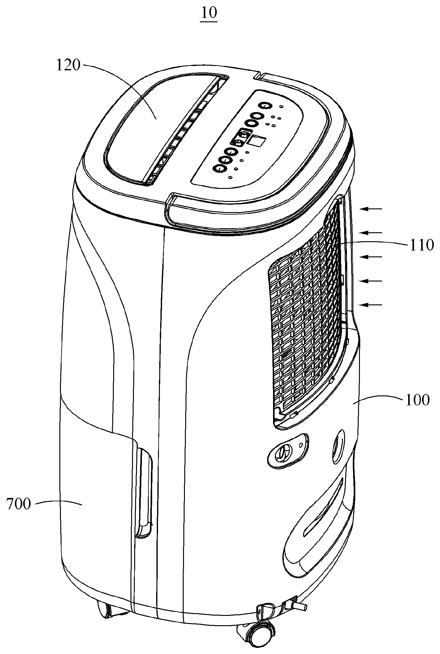
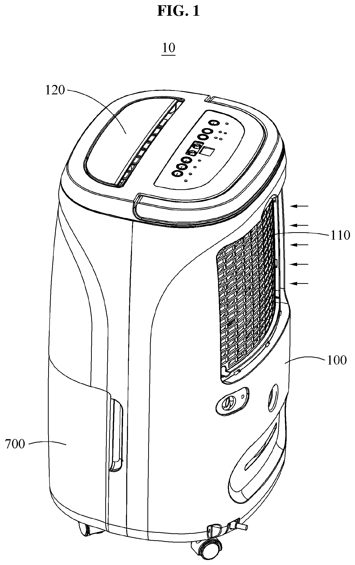
[0029] FIG. 1 is a perspective view illustrating a dehumidifier according to an example embodiment.
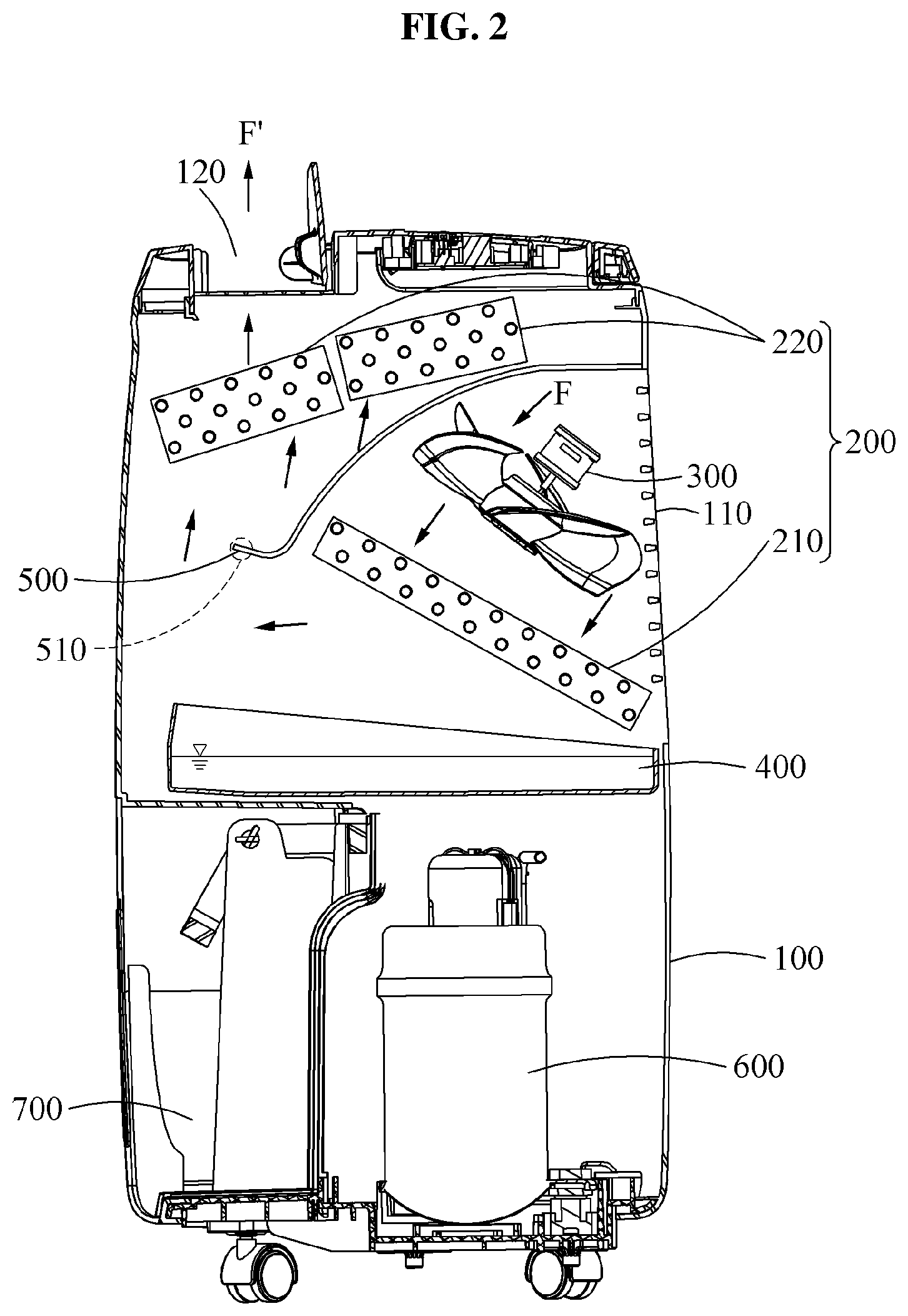
[0030] FIG. 2 illustrates an example of a dehumidifier viewed from side according to an example embodiment.
[0031] FIG. 3 illustrates another example of a dehumidifier viewed from front according to an example embodiment.
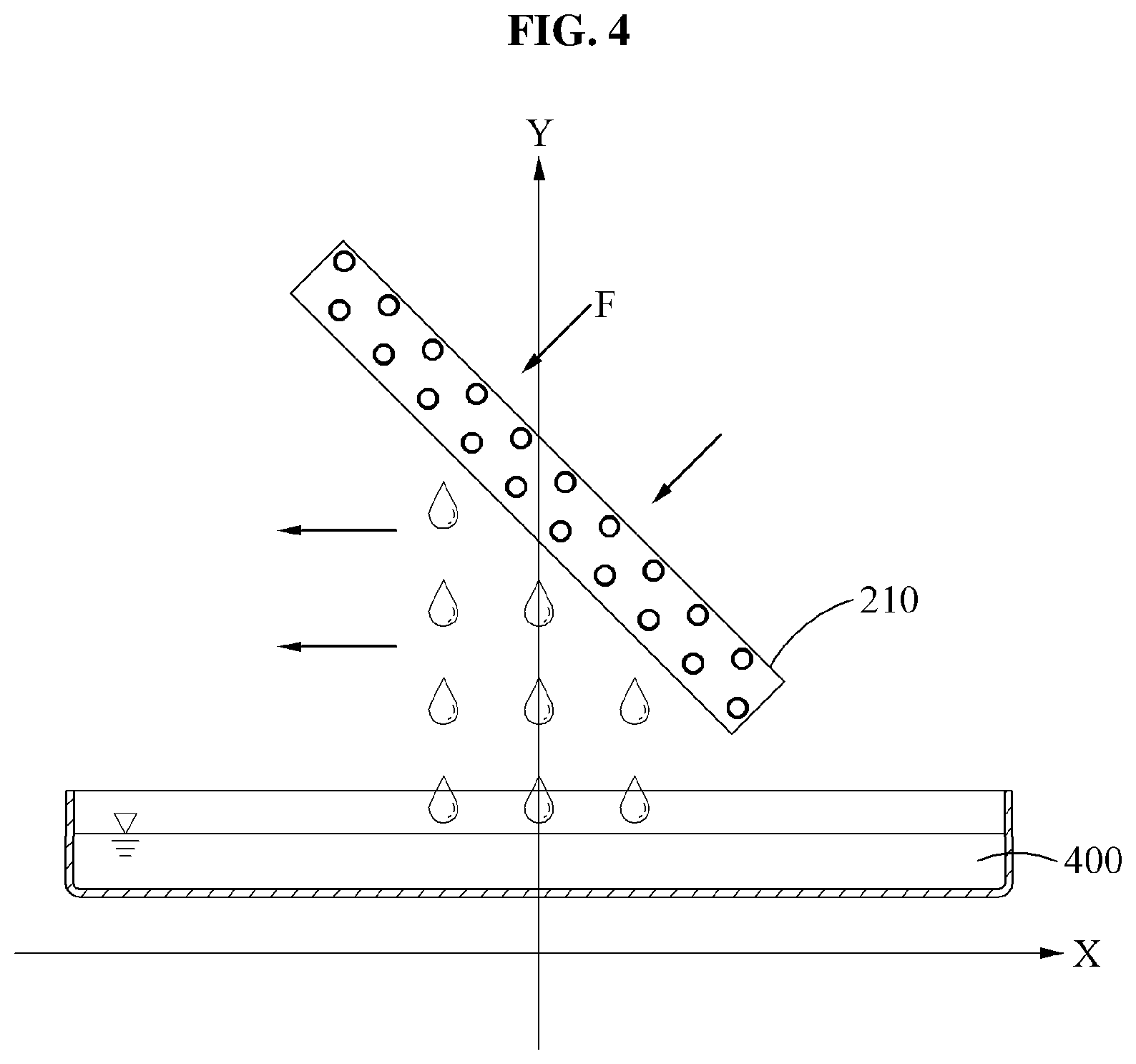
[0032] FIG. 4 illustrates an example of removing condensate water from an evaporator.
BEST MODE FOR CARRYING OUT THE INVENTION
[0033] Hereinafter, example embodiments will be described with reference to the accompanying drawings. The following description is provided according to some aspects of the example embodiments, and forms part of a detailed description of the example embodiments.
[0034] Also, descriptions of functions and constructions that are well known to one of ordinary skill in the art may be omitted for increased clarity and conciseness.
[0035] It should be understood that the terms used in the specification and the appended claims should not be construed as limited to general and dictionary meanings, but interpreted based on the meanings and concepts corresponding to technical aspects of a dehumidifier of the disclosure based on the principle that the inventor is allowed to define terms.
[0036] Accordingly, the description proposed herein is merely an example for the purpose of illustration, and is not intended to represent all technical aspects related to the hybrid powertrain apparatus of the disclosure, so it should be understood that other equivalents and modifications could be made thereto without departing from the spirit and scope of the disclosure.
[0037] FIG. 1 is a perspective view illustrating a dehumidifier according to an example embodiment. FIG. 2 illustrates an example of a dehumidifier viewed from side according to an example embodiment. FIG. 3 illustrates another example of a dehumidifier viewed from front according to an example embodiment. FIG. 4 illustrates an example of removing condensate water from an evaporator.
[0038] Referring to FIGS. 1 and 2, a dehumidifier 10 may include a body 100 and a heat exchanger 200. The body 100 may suction air through an inlet 110 and discharge the air through an outlet 120. The heat exchanger 200 may include an evaporator 210 and a condenser 220 and remove moisture in the air suctioned through the inlet 110.
[0039] The evaporator 210 may cool air F suctioned through the inlet 110 to condense moisture in the air F. The condenser 220 may be disposed above the evaporator 210 to condense a refrigerant used in the dehumidifier and heat air F' passing through the evaporator 210.
[0040] The dehumidifier 10 may include a blower 300 disposed between the inlet 110 and the heat exchanger 200 to guide air from the inlet 110 to the evaporator 210 of the heat exchanger 200, and an accommodator 400 disposed under the evaporator 210 to accommodate dehumidification water generated in the evaporator 210.
[0041] The dehumidifier 10 may further include a compressor 600 disposed below the accommodator 400 to compress a gaseous refrigerant at a high temperature and a high pressure, and a water tank 700 detachably attached to the body 100 and located in a front part of the body 100. The water tank 700 may receive the dehumidification water accommodated in the accommodator 400 and store the dehumidification water.
[0042] The evaporator 210 may be obliquely disposed based on a longitudinal axis of the body 100 to face the accommodator 400, so that the dehumidification water condensed in the evaporator 210 falls into the accommodator 400 by force of gravity.
[0043] In other words, the evaporator 210 may tilt toward a ground or a lower surface of the body 10, rather than vertically disposed with respect to the ground or the lower surface of the body 100. However, embodiments are not limited thereto, and the evaporator 210 may also be disposed horizontally with respect to the ground or the lower surface of the body 100.
[0044] In this case, the condensate water formed on the evaporator 210 may be removed from the evaporator 210 more quickly than in a case in which the evaporator 210 is disposed vertical to the ground or the lower surface of the body 100 of the dehumidifier. This is because the condensate water formed on a part of the evaporator 210 directly falls toward the accommodator 400 by force of gravity without passing through another part of the evaporator 210.
[0045] The condenser 220 may be obliquely disposed above the evaporator 210 based on the longitudinal axis of the body 100 to face an upper surface of the body 100, so that the air passing the evaporator 210 rises toward the condenser 220. This is because a guide 500 is provided to guide the air passing through the evaporator 210 to travel toward the upper surface of the body 100.
[0046] The dehumidifier 10 may further include the guide 500 disposed between the evaporator 210 and the condenser 220.
[0047] The guide 500 may extend from an upper end of the inlet 110 toward an inside of the body 100 and be formed in a shape that covers the evaporator 210 and the blower 300 and the evaporator 210. A lower end 510 of the guide may be bent in a direction away from the evaporator 210 or in a direction toward the condenser 220. Accordingly, the air passing the evaporator 210 may be guided by the guide 200 to the condenser 220.
[0048] In this example, the blower 300 may be obliquely disposed based on the longitudinal axis of the body 100 to face the accommodator 400.
[0049] In other words, like the evaporator 210, the blower 200 may also tilt toward the ground or the lower surface of the body 10 rather than being disposed vertical to the ground or the lower surface of the body 100.
[0050] This is so that a flow direction of the air F suctioned through the inlet 110 is directed toward the accommodator 400 or the lower surface of the body 100 by arranging the blower 300 to be tilted. Through this, the air F suctioned through the inlet 110 may thoroughly pass through the tilted evaporator 210.
[0051] The inlet 110 may be formed in a rear surface of the body 100 and, the outlet 120 may be formed in a top surface of the body 100. In this example, the blower 300 may allow the air F suctioned through the inlet 110 to travel toward the evaporator 210 so as to be dehumidified. Also, the air F' passing through the evaporator 210 may pass the condenser 220, and then be discharged to an outside through the outlet 120.
[0052] In the dehumidifier 10 having the above structure, the blower 300 may allow the air F suctioned through the inlet 110 to pass through the tilted evaporator 210 while travelling toward the accommodator 400 or the lower surface of the body 100.
[0053] Thereafter, the air may be cooled while passing through the evaporator 210. Also, the condensate water may be formed on the evaporator 210. Through this, the air may be dehumidified. In this example, the evaporator 210 may be obliquely disposed based on the ground or the lower surface of the body 100, so that the condensate water formed on the evaporator 210 is more quickly removed by force of gravity. As such, by quickly removing the condensate water from the evaporator 210, a temperature of the evaporator 210 may be reduced. In addition, a heat exchange between the evaporator 210 and the air passing through the evaporator 210 may be actively performed such that a dehumidification efficiency is improved.
[0054] The dehumidified air may be guided by the guide 500 toward the condenser 220 disposed above the evaporator 210. A temperature of the dehumidified air may increase while passing through the condenser 220. The dehumidified air having the increased temperature may be discharged to the outside through the outlet 120. In this instance, dehumidification water condensed in the evaporator 210 may fall into the accommodator 500 and the dehumidification water accommodated in the accommodator 500 may be stored in the water tank 700.
[0055] In this example, an air flow path may be flexibly designed by arranging the condenser 220 above the evaporator 210 and arranging the guide 500 between the evaporator 210 and the condenser 220. The flexible air flow path may reduce noise and vibration.
[0056] Referring to FIG. 3, a dehumidifier 10 may include a body 100 that suctions air through an inlet 110 and discharges the air through an outlet 120, an accommodator 400 disposed in the body 100 to accept dehumidification water, a blower 300 disposed above the accommodator 400 to guide the air suctioned through the inlet 110 toward the accommodator 400, an evaporator 210 disposed between the blower 300 and the accommodator and 400 to cool the suctioned air to condense moisture in the air, and a condenser 220 that heats the air having passed the evaporator 210 while condensing a refrigerant used in the dehumidifier.
[0057] The evaporator 210 and the blower 300 may be are obliquely disposed based on a longitudinal axis y of the body 100 to face the accommodator 400, so that the dehumidification water condensed in the evaporator 210 falls into the accommodator 400 by force of gravity.
[0058] The dehumidifier 100 may further include a guide 500 disposed above the evaporator 210 and the blower 400.
[0059] The guide 500 may be formed to cover the blower 400 and the evaporator 210. A lower end of the guide 500 may be bent in a direction away from the evaporator 210 or in a direction toward an upper surface of the body 100, so that the air passing the evaporator 210 is guided along the guide toward a side surface or the upper surface of the body 100.
[0060] The condenser 220 may be disposed between the upper surface of the body 100 and the guide 500. The air passing the evaporator 210 may rise toward the condenser 220.
[0061] In this example, the inlet 110 may be formed in a front surface or a rear surface of the body 100. Also, the outlet 120 may be formed in a top surface of the body 100. The blower 300 may allow the air suctioned through the inlet 110 to travel toward the evaporator 210. The air passing the evaporator 210 may pass the condenser 220 to be discharged through the outlet 120 to an outside.
[0062] Accordingly, as illustrated in FIG. 4, in the dehumidifier, the condensate water formed on the evaporator 210 may be quickly removed and fall into the accommodator 400. Through this, a temperature of the evaporator 210 may be reduced. Also, a heat exchange between the evaporator 210 and the air passing through the evaporator 210 may be actively performed such that a dehumidification efficiency is improved.
[0063] While this disclosure includes specific examples, it will be apparent to one of ordinary skill in the art that various changes in form and details may be made in these examples without departing from the spirit and scope of the claims and their equivalents. The examples described herein are to be considered in a descriptive sense only, and not for purposes of limitation. Descriptions of features or aspects in each example are to be considered as being applicable to similar features or aspects in other examples. Therefore, the scope of the disclosure is defined not by the detailed description, but by the claims and their equivalents, and all variations within the scope of the claims and their equivalents are to be construed as being included in the disclosure.
* * * * *
D00000
D00001
D00002
D00003
D00004
XML
uspto.report is an independent third-party trademark research tool that is not affiliated, endorsed, or sponsored by the United States Patent and Trademark Office (USPTO) or any other governmental organization. The information provided by uspto.report is based on publicly available data at the time of writing and is intended for informational purposes only.
While we strive to provide accurate and up-to-date information, we do not guarantee the accuracy, completeness, reliability, or suitability of the information displayed on this site. The use of this site is at your own risk. Any reliance you place on such information is therefore strictly at your own risk.
All official trademark data, including owner information, should be verified by visiting the official USPTO website at www.uspto.gov. This site is not intended to replace professional legal advice and should not be used as a substitute for consulting with a legal professional who is knowledgeable about trademark law.