Drive Flank Engagement Between Rotating Components and Shaft of Electrical Submersible Well Pump
Williams; Brett T. ; et al.
U.S. patent application number 16/425633 was filed with the patent office on 2019-12-05 for drive flank engagement between rotating components and shaft of electrical submersible well pump. This patent application is currently assigned to Baker Hughes Oilfield Operations LLC. The applicant listed for this patent is Baker Hughes Oilfield Operations LLC. Invention is credited to Risa Rutter, Brett T. Williams, Zheng Ye.
| Application Number | 20190368511 16/425633 |
| Document ID | / |
| Family ID | 68693092 |
| Filed Date | 2019-12-05 |


| United States Patent Application | 20190368511 |
| Kind Code | A1 |
| Williams; Brett T. ; et al. | December 5, 2019 |
Drive Flank Engagement Between Rotating Components and Shaft of Electrical Submersible Well Pump
Abstract
A well pump has a shaft with at least one shaft drive flank extending a length of the shaft. Impellers are located between non-rotating diffusers. Each impeller has a hub with an impeller hub bore through which the shaft extends. The impeller hub bore has at least one impeller drive flank that is in flush contact with the shaft drive flank to impart rotation to the impeller. The shaft drive flanks may be on opposite sides of the shaft and parallel with each other. The shaft may have six of the shaft drive flanks symmetrically arranged around the shaft and joining each other. The shaft drive flanks may be three involute curved surfaces that join each other.
| Inventors: | Williams; Brett T.; (Claremore, OK) ; Rutter; Risa; (Claremore, OK) ; Ye; Zheng; (Tulsa, OK) | ||||||||||
| Applicant: |
|
||||||||||
|---|---|---|---|---|---|---|---|---|---|---|---|
| Assignee: | Baker Hughes Oilfield Operations
LLC Houston TX |
||||||||||
| Family ID: | 68693092 | ||||||||||
| Appl. No.: | 16/425633 | ||||||||||
| Filed: | May 29, 2019 |
Related U.S. Patent Documents
| Application Number | Filing Date | Patent Number | ||
|---|---|---|---|---|
| 62678313 | May 31, 2018 | |||
| Current U.S. Class: | 1/1 |
| Current CPC Class: | F04D 7/04 20130101; F04D 29/708 20130101; F04D 1/06 20130101; F04D 13/10 20130101; F04D 29/20 20130101 |
| International Class: | F04D 29/70 20060101 F04D029/70; F04D 1/06 20060101 F04D001/06; F04D 7/04 20060101 F04D007/04; F04D 29/20 20060101 F04D029/20 |
Claims
1. A well pump assembly, comprising: a pump having a housing with a longitudinal axis; a shaft extending through the housing on the axis, the shaft having at least one shaft drive flank integrally formed thereon and extending substantially a length of the shaft; a plurality of diffusers fixed in the housing against rotation, each of the diffusers having diffuser passages extending from a diffuser inlet to a diffuser outlet, each of the diffusers having a diffuser bore through which the shaft extends; and an impeller located between each of the diffusers, the impeller having impeller passages extending from an impeller inlet to an impeller outlet, the impeller having an impeller hub with an impeller hub bore through which the shaft extends, the impeller hub bore having at least one impeller drive flank integrally formed therein that is in flush contact with the shaft drive flank to impart rotation to the impeller.
2. The pump assembly according to claim 1, wherein the at least one shaft drive flank comprises a plurality of shaft drive flanks symmetrically arranged around an exterior of the shaft.
3. The pump assembly according to claim 1, wherein the at least one shaft drive flank comprises two of the shaft drive flanks on opposite sides of the shaft and parallel with each other.
4. The pump assembly according to claim 1, wherein the at least one impeller drive flank comprises at least six of the impeller drive flanks symmetrically arranged around the impeller hub bore and joining each other.
5. The pump assembly according to claim 1, wherein the at least one impeller drive flank comprises three involute curved surfaces that join each other.
6. The pump assembly according to claim 1, wherein the at least one impeller drive flank comprises a single flat surface asymmetrically formed in the impeller hub bore.
7. The pump assembly according to claim 1, further comprising: spacer rings through which the shaft extends, the spacer rings being positioned between and in abutment with the impeller hub, each of the spacer rings having a bore through which the shaft passes, the bore in the each of the spacer rings having at least one spacer ring drive flank that mates with the shaft drive flank.
8. The pump assembly according to claim 1, further comprising: a shaft coupling on a driven end of the shaft, the shaft coupling having a coupling bore with at least one coupling drive flank that mates with the shaft drive flank.
9. The pump assembly according to claim 1, wherein: an exterior of the impeller hub is cylindrical and in rotating, sliding contact with the diffuser bore in one of the diffusers.
10. A well pump assembly, comprising: a pump having a housing with a longitudinal axis; a shaft extending through the housing on the axis, the shaft having at least one shaft drive flank extending substantially a length of the shaft, wherein a line normal to a midpoint of the shaft drive flank passes through the axis; a plurality of diffusers fixed in the housing against rotation, each of the diffusers having diffuser passages extending from a diffuser inlet to a diffuser outlet, each of the diffusers having a diffuser bore through which the shaft passes but does not contact; and an impeller located between each of the diffusers, the impeller having impeller passages extending from an impeller inlet to an impeller outlet, the impeller having an impeller hub with an impeller hub bore through which the shaft extends, the impeller hub bore having at least one impeller drive flank integrally formed therein that mates with the shaft drive flank to impart rotation to the impeller, wherein a line normal to a midpoint of the impeller drive flank passes through the axis.
11. The pump assembly according to claim 10, wherein: the impeller hub has a cylindrical exterior with a wall thickness measured between the impeller drive flank and the cylindrical exterior; the wall thickness between the impeller drive flank and the cylindrical exterior is greatest at the midpoint of the impeller drive flank; and the wall thickness between the impeller drive flank and the cylindrical exterior is least at ends of the impeller drive flank.
12. The pump assembly according to claim 10, wherein the at least one impeller drive flank comprises two flat surfaces formed on opposite sides of the impeller hub bore, the flat surfaces being parallel with each other.
13. The pump assembly according to claim 10, wherein the at least one impeller drive flank comprises six flat surfaces, defining a hexagonal configuration for the impeller hub bore.
15. The pump assembly according to claim 10, wherein: the at least one impeller drive flank comprises three involute, curved surfaces formed in the impeller hub bore; and each of the curved surfaces has a radial center point that is offset from the axis.
16. The pump assembly according to claim 10, wherein the impeller drive flank comprises a single flat surface formed on one side of the impeller hub bore.
17. A well pump assembly, comprising: a pump having a housing with a longitudinal axis; a shaft extending through the housing on the axis, the shaft having a plurality of shaft drive flanks extending substantially a length of the shaft and symmetrically arranged around the shaft; a plurality of diffusers fixed in the housing against rotation, each of the diffusers having diffuser passages extending from a diffuser inlet to a diffuser outlet, each of the diffusers having a diffuser bore through which the shaft passes but does not contact; and a plurality of impellers, each of the impellers being located between each of the diffusers, each of the impellers having impeller passages extending from an impeller inlet to an impeller outlet, each of the impellers having an impeller hub with an impeller hub bore through which the shaft extends, the impeller hub bore having a plurality of impeller drive flanks, each of the impeller drive flanks being in flush contact with one of the shaft drive flanks.
18. The pump assembly according to claim 17, wherein: the shaft drive flanks are flat, on opposite sides of the shaft and parallel with each other.
19. The pump assembly according to claim 17, wherein the shaft drive flanks comprise six flat surfaces symmetrically arranged around the shaft and joining each other.
20. The pump assembly according to claim 17, wherein the shaft drive flanks comprise three involute curved surfaces that join each other.
Description
CROSS-REFERENCE TO RELATED APPLICATION
[0001] This application claims priority to provisional application 62/678,313 filed May 31, 2018.
BACKGROUND
[0002] One type of submersible well fluid pump has an electrical motor operatively connected with a centrifugal pump. The pump has a large number of stages, each stage having an impeller and a diffuser. A shaft rotated by the motor rotates the impellers relative to the diffusers. Each impeller has passages that lead upward and outward to the next upward diffuser. Each diffuser has passages that extend upward and inward to the next upward impeller.
[0003] The impellers and the shaft have mating keyway slots in which a key is positioned to lock the impellers to the shaft for rotation. While successful, during operation, sand from the well fluid flowing through the pump may accumulate in the keyway slots, creating problems.
SUMMARY
[0004] A well pump assembly comprises a pump having a housing with a longitudinal axis. A shaft extends through the housing on the axis, the shaft having at least one shaft drive flank integrally formed thereon and extending substantially a length of the shaft. A plurality of diffusers are fixed in the housing against rotation, each of the diffusers having diffuser passages extending from a diffuser inlet to a diffuser outlet. Each of the diffusers has a diffuser bore through which the shaft extends. An impeller is located between each of the diffusers. The impeller has impeller passages extending from an impeller inlet to an impeller outlet. The impeller has an impeller hub with an impeller hub bore through which the shaft extends. The impeller hub bore has at least one impeller drive flank integrally formed therein that is in flush contact with the shaft drive flank to impart rotation to the impeller.
[0005] In some embodiments, the at least one shaft drive flank comprises a plurality of shaft drive flanks symmetrically arranged around an exterior of the shaft. In one embodiment, the at least one shaft drive flank comprises two of the shaft drive flanks on opposite sides of the shaft and parallel with each other. In another embodiment, the at least one impeller drive flank comprises at least six of the impeller drive flanks symmetrically arranged around the impeller hub bore and joining each other. In still another embodiment, the at least one impeller drive flank comprises three involute curved surfaces that join each other. The at least one impeller drive flank may comprise a single flat surface asymmetrically formed in the impeller hub bore.
[0006] The pump may have spacer rings through which the shaft extends. The spacer rings are positioned between and in abutment with the impeller hub. Each of the spacer rings has a bore through which the shaft passes. The bore in the each of the spacer rings has at least one spacer ring drive flank that mates with the shaft drive flank.
[0007] The pump may have a shaft coupling on a driven end of the shaft. The shaft coupling has a coupling bore with at least one coupling drive flank that mates with the shaft drive flank.
[0008] An exterior of the impeller hub is cylindrical and in rotating, sliding contact with the diffuser bore in one of the diffusers.
BRIEF DESCRIPTION OF THE DRAWINGS
[0009] FIG. 1 is a schematic side view of an electrical submersible pump assembly in accordance with this disclosure.
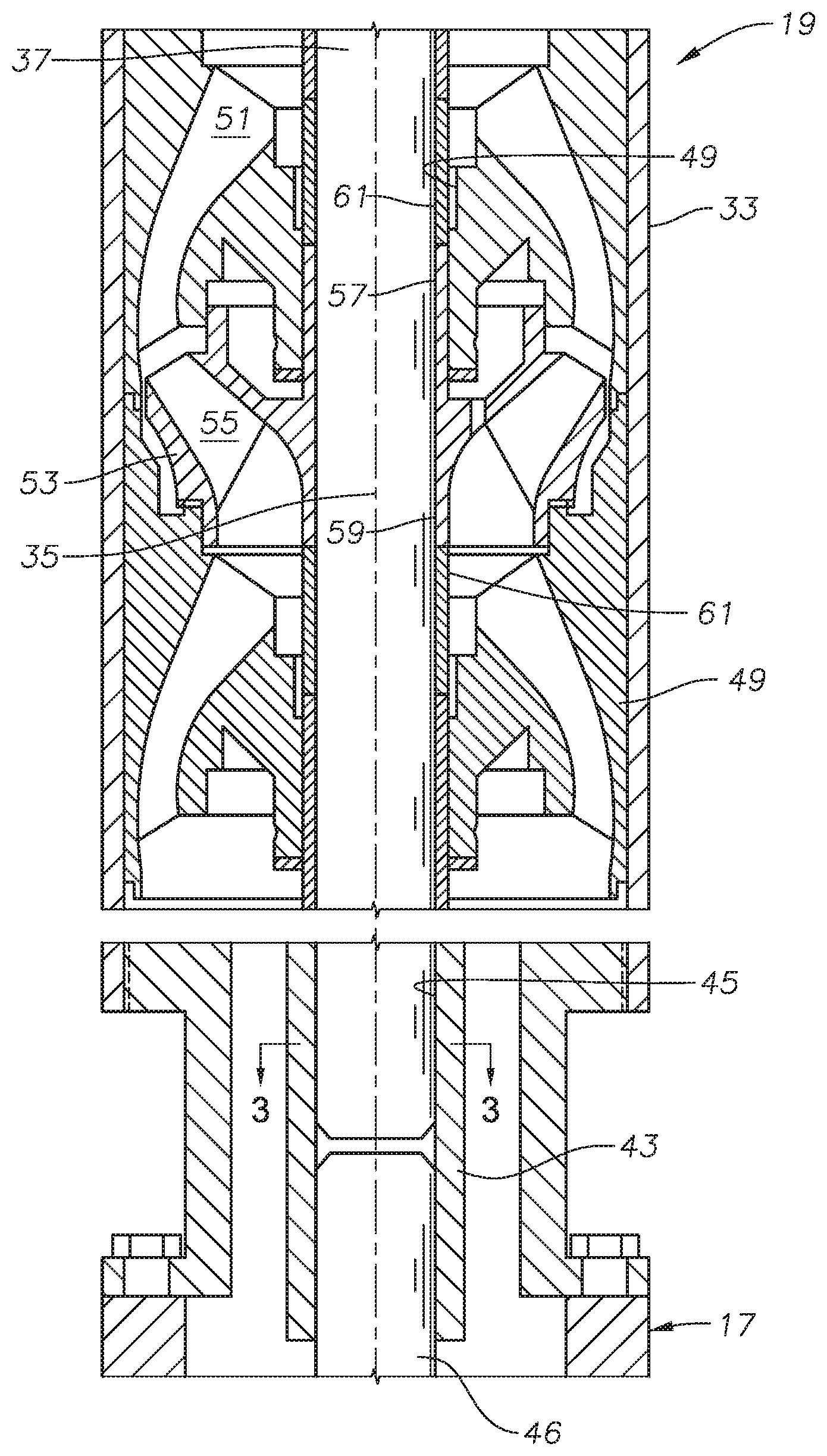
[0010] FIG. 2 is a sectional view of a portion of the pump of FIG. 1.
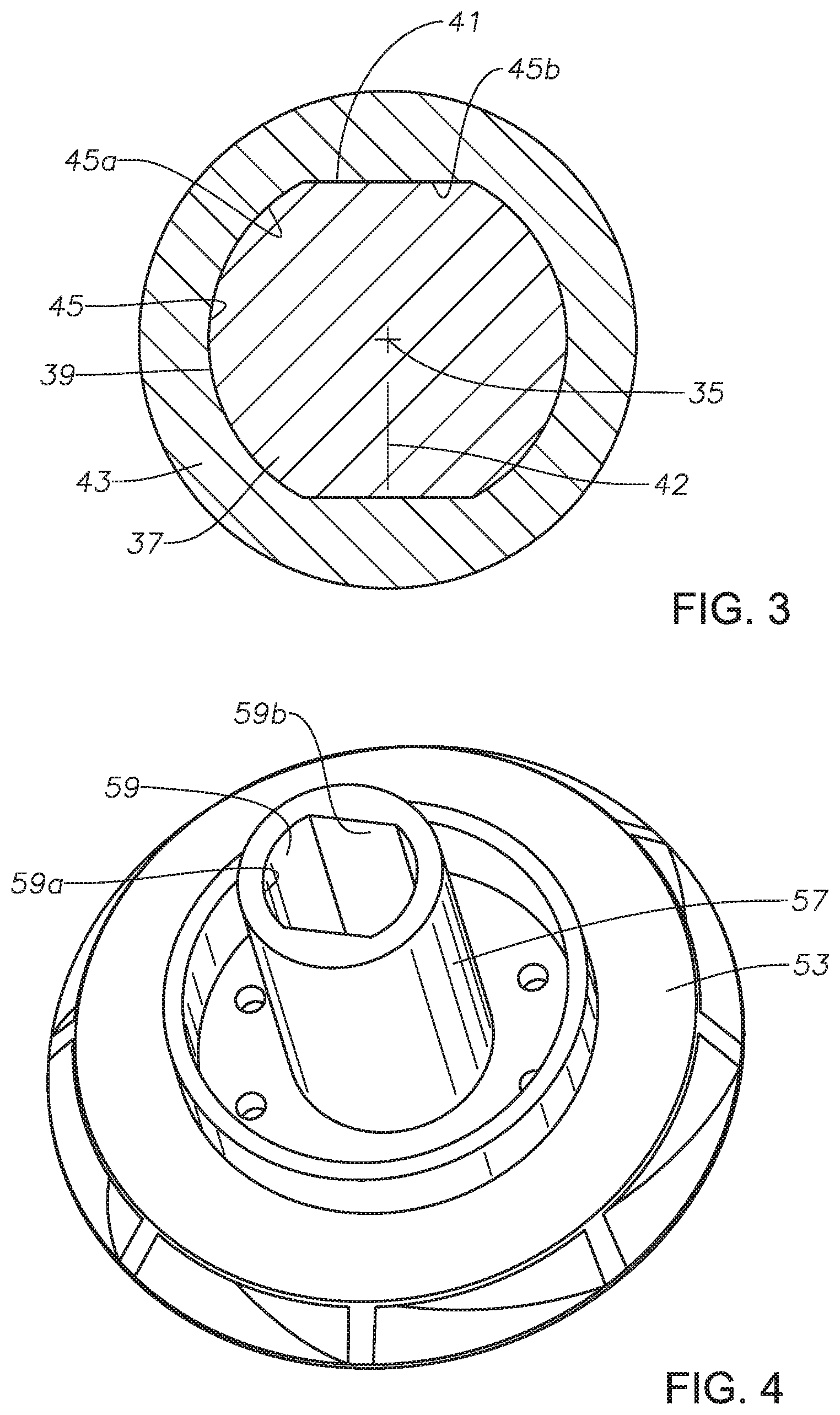
[0011] FIG. 3 is a sectional view of the shaft and a coupling of the pump of FIG. 2, taken along the line 3-3 of FIG. 2.
[0012] FIG. 4 is an perspective view from an upper side of one of the impellers of the pump of FIG. 1, shown removed from the pump.
[0013] FIG. 5 is a top view of the impeller of FIG. 4.
[0014] FIG. 6 is top view of an alternate embodiment of the impeller of FIG. 4.
[0015] FIG. 7 is a transverse sectional view of the hub of an alternate embodiment of one of the impellers of FIGS. 2 and 4.
[0016] FIG. 8 is a perspective view of a portion of the impeller hub of FIG. 7.
[0017] FIG. 9 is a transverse sectional view of the hub of another alternate embodiment of the impellers of FIGS. 2 and 4.
[0018] FIG. 10 is a perspective view of a portion of the impeller hub of FIG. 9.
[0019] While the disclosure will be described in connection with the preferred embodiments, it will be understood that it is not intended to limit the disclosure to that embodiment. On the contrary, it is intended to cover all alternatives, modifications, and equivalents, as may be included within the scope of the disclosure as defined by the appended claims.
DETAILED DESCRIPTION OF THE DISCLOSURE
[0020] The method and system of the present disclosure will now be described more fully hereinafter with reference to the accompanying drawings in which embodiments are shown. The method and system of the present disclosure may be in many different forms and should not be construed as limited to the illustrated embodiments set forth herein; rather, these embodiments are provided so that this disclosure will be thorough and complete, and will fully convey its scope to those skilled in the art. Like numbers refer to like elements throughout. In an embodiment, usage of the term "about" includes +/-5% of the cited magnitude. In an embodiment, usage of the term "substantially" includes +/-5% of the cited magnitude.
[0021] It is to be further understood that the scope of the present disclosure is not limited to the exact details of construction, operation, exact materials, or embodiments shown and described, as modifications and equivalents will be apparent to one skilled in the art. In the drawings and specification, there have been disclosed illustrative embodiments and, although specific terms are employed, they are used in a generic and descriptive sense only and not for the purpose of limitation.
[0022] Referring to FIG. 1, a well with casing 11 is illustrated as containing an electrical submersible pump assembly (ESP) 13. ESP 13 has a motor 15, which is normally a three phase electrical motor. Motor 15 is filled with a dielectric motor lubricant. A pressure equalizer or seal section 17 has features to equalize the internal pressure of the motor lubricant with the hydrostatic pressure of well fluid surrounding motor 15. Seal section 17 may be located above motor 15, as shown, and will be in fluid communication with the motor lubricant in motor 15. Alternately, a pressure equalizer could be located below motor 15. Motor 15 has a drive shaft assembly that extends through seal section 17 and drives a centrifugal pump 19, which has an intake 21 for drawing well fluid in.
[0023] A string of production tubing 23 extends to a wellhead (not shown) and supports ESP 13. Tubing 23 may comprise sections secured together by threads. Alternately, tubing 23 may comprise continuous coiled tubing. A power cable 25 extends downward from the wellhead and is strapped to tubing 23. A motor lead 27 connects to power cable 25 at a splice or connection 29 located above ESP 13. Motor lead 27 extends alongside ESP 13 and has a motor lead connector 31 on its lower end that plugs into a receptacle at the upper end of motor 15. Pump 19 discharges well fluid through its upper end into tubing 23 in this example. If tubing 23 is continuous coiled tubing, power cable 25 could be located inside the coiled tubing, in which case, pump 19 would discharge into an annulus surrounding the coiled tubing.
[0024] Motor 15, pump 19 and seal section 17 comprise modules that are brought separately to a well site, then secured together by bolted flanges or threaded collars. ESP 13 may have other modules, such as a gas separator and a thrust bearing unit. Alternately, a thrust bearing unit could be formed as part of seal section 17. Also, motor 15, pump 19 and seal section 17 each could be formed in more than one module and connected in tandem.
[0025] Referring to FIG. 2, pump 19 has a tubular housing 33 with a cylindrical inner side wall concentric with a longitudinal axis 35. A steel drive shaft 37 extends through housing 33 concentric with axis 35. Shaft 37 can be lengthy; for example, shaft 37 may be 20-30 feet in length. Referring to FIG. 3, shaft 37 has an exterior surface with cylindrical portions 39 joined by drive flanks 41, which in this example comprises two. Drive flanks 41 are flat surfaces parallel with each other and on opposite sides of shaft 37 that are integrally formed in the cylindrical exterior surface 39. Drive flanks 41 may vary in width, and in this example, each drive flank has a width from one side edge to another of about half the diameter of shaft 37 measured between cylindrical portions 39. Cylindrical portions 39 are on opposite sides of shaft 37 and have the same diameters.
[0026] Positioning drive flanks 41 on opposite sides of shaft 37 and parallel to each other makes drive shaft 37 symmetrical, reducing vibration. A line 42 normal to one of the drive flanks 41 and at a midpoint between the side edges of the drive flank 41 passes through axis 35 and through the midpoint of the opposite drive flank 41. Similarly, a line normal to the midpoint of one of the cylindrical portions 39 passes through axis 35 and through the midpoint of the opposite cylindrical portion 39. Drive flanks 41 are formed in one method by machining a cylindrical shaft.
[0027] Drive flanks 41 extend substantially the length of the shaft. In this example, drive flanks 41 extend continuously to at least one end of shaft 37, such as the lower end. A coupling 43 slides over the lower end of shaft 37 and couples shaft 37 to another shaft 46, such as shaft 46 of seal section 17, which in turn is driven by the shaft of motor 15 (FIG. 1). Shaft 46 may be considered to be a motor shaft or a driving shaft. The lower end of shaft 37 may be considered to be the driven end of shaft 37.
[0028] In this example, at least the upper half of coupling 43 has a coupling bore 45 with two cylindrical portions 45a joined by two drive flanks 45b. The dimensions of coupling bore 45 mate with drive shaft 37 to cause drive shaft 37 to rotate in unison. Coupling bore drive flanks 45b have the same dimensions as shaft drive flanks 41, and coupling bore cylindrical portions 45a have the same dimension as shaft cylindrical portions 39, within close tolerances. Coupling 43 has a wall thickness measured from bore 45 to the cylindrical exterior surface. The wall thickness is uniform where measured from the cylindrical portion of bore 45 to the exterior. The wall thickness from the cylindrical exterior to one of the coupling drive flanks 45b increases from the side edges of the drive flank 45b to a greatest thickness at the midpoint where intersected by line 42.
[0029] Shaft 46 within seal section 19 (FIG. 1) may have an upper end with drive flanks in the same manner as pump shaft 37 for sliding into a lower portion of coupling 43. Alternatively, the upper end of seal section shaft 46 could be splined with conventional triangular splines. If splined, the lower portion of coupling bore 45 would have mating splines.
[0030] In this example, the upper end of pump shaft 37 is not coupled to a shaft in another module. The exterior of shaft 37 at the upper end could be completely cylindrical, or it could have splines or it could have drive flanks 41. In the case of a tandem pump (not shown) mounted above pump 19, the upper end of drive shaft 37 could utilize drive flanks 41. If so, an upper drive shaft coupling with drive flanks similar to coupling 43 could be employed on the upper end of pump shaft 37.
[0031] A stack of diffusers 47 (only two shown) fits closely in housing 33 for non-rotation. Diffusers 47 may be identical, each having a central coaxial diffuser bore 49 through which drive shaft 37 extends but does not contact. Each diffuser bore 49 is cylindrical. Each diffuser 37 has diffuser passages 51 that extend from a lower inlet upward and radially inward to an upper outlet.
[0032] An impeller 53 (only one shown) mounts between each of the diffusers 47. Impeller 53 has impeller passages 55 that extend upward and outward from a lower inlet to an upper outlet. Impeller 53 has a cylindrical hub 57 extending upward and outward into diffuser bore 49 of the next upward diffuser 47. Impeller 53 has an impeller bore 59 extending from its lower side to its upper side through which shaft 37 extends.
[0033] Referring to FIGS. 4 and 5, in this embodiment, impeller bore 59 has two cylindrical portions 59a joined by two flat drive flanks 59b. Cylindrical portions 59a and drive flanks 59b are dimensioned to mate and be in flush contact with shaft drive flanks 41, within close tolerances. Shaft drive flanks 41 cause impeller 53 to rotate in unison. Although is a sectional view of coupling 43, it also represents the engagement of shaft drive flats 41 with impeller drive flanks 59b. Other than impeller bore 59, the remaining configuration of impeller 53 may be conventional. The discussion of the features of drive flanks 45b in coupling 43 also applies to impeller drive flanks 59b.
[0034] Spacer rings 61 encircle shaft 37 and are located between impellers 53. Spacer rings 61 abut the upper end of the hub 57 of a next lower impeller 53 and the lower side of the next upward impeller 53. Each spacer ring 61 rotates with shaft 37 and has a bore 63 with drive flanks that mate with drive flanks 41 of shaft 37. The cross-section of one of the spacer rings 61 would appear to be the same as the cross-section of coupling 43 of FIG. 3. The discussion above of the features of coupling drive flanks 45b also applies to the drive flanks in spacer ring 61.
[0035] During assembly, a technician alternates sliding each diffuser 47 over shaft 35 with sliding one of the impellers 53 and one or more of the spacer rings 61. If the lower end of shaft 37 is the only end having drive flanks 41, the technician would slide the diffusers 47, impellers 53 and spacer rings 61 over the lower end.
[0036] Impellers 53 are free to slide upward and downward short distances on drive shaft 37 between down thrust and up thrust conditions. In the up thrust conditions, an upper side portion of impeller 53 abuts a thrust washer on the lower side of the next upward diffuser 47. In the down thrust condition, a lower side portion of impeller 53 abuts a thrust washer on an upper side of the next downward diffuser 47. Shaft drive flanks 41 can also cause impellers 53 to spin shaft 37 in reverse rotation due to a falling column of well fluid in production tubing 23 in the event motor 15 shuts off.
[0037] In many well installations, motor 15 (FIG. 1) is operated at a fixed speed that is typically about 3600 rotations per minute (RPM). Alternately, a variable speed drive near the wellhead (not shown) may change the rotational speed of the motor from less than 3600 RPM to more.
[0038] Impellers 53 may be constructed of conventional materials, such as a casting of a nickel iron alloy. The dimensions of impeller bore 59 can be finalized by broaching.
[0039] Referring to alternate embodiment of FIG. 6, impeller 65 has a bore 67 with more than two drive flanks 69. In this example, there are six drive flanks 69, but the number could be more or less. Bore 67 has no cylindrical portions. Drive flanks 69 are flat surfaces with edges joining each other at 120 degree included angles to define a hexagonal configuration for bore 67. As in FIG. 3, a line (not shown) normal to each drive flank 69 at its midpoint will pass through the axis of rotation. The exterior of the hub of impeller 65 is cylindrical, thus the wall thickness measured from drive flanks 69 to the cylindrical exterior will change. The thickest portion of the wall of the hub of impeller 65 will be at the midpoint between side edges of each drive flank 69. The thinnest wall thickness portion will be at the side edges of each impeller drive flank 69.
[0040] Drive shaft 37 (FIG. 2) will have a mating hexagonal configuration that closely receives each impeller 65. A hexagonal exterior for drive shaft 37 is also symmetrical, reducing vibration. Other than having hexagonal drive flanks 69, impeller 65 may be the same as impellers 53.
[0041] FIGS. 7 and 8 illustrate another embodiment of an impeller hub 71. FIGS. 7 and 8 do not show the remaining portions of the impeller of hub 71, but they may be the same as impeller 53 (FIGS. 2 and 4). Impeller hub 71 has three internal drive flanks 73 with side edges that join each other. Each drive flank 73 is a curved involute surface with a separate radial center point 75 offset from axis 77 of rotation. Each curved flank 73 is formed with a radius 79 extending from a radial center point 75. Radius 79 has a greater length than a radial line extending from rotational axis 77 to any part of any of the impeller drive flanks 73. The radial center point 75 for each drive flank 73 will be at a different location from the radial center points of the other drive flanks 73. A line 80 normal to each drive flank 73 at a midpoint between the side edges of each drive flank 73 will pass through axis 77.
[0042] The drive shaft (not shown) for impeller hub 71 will have curved involute drive flanks on its exterior surface that mates in flush contact with drive flanks 73. The curved drive flanks on the drive shaft extend substantially a full length of the drive shaft in the same manner as drive flats 41 (FIG. 3). Spacer rings (not shown) similar to spacer rings 61 (FIG. 2) would have similar internal curved drive flanks in their bores. A coupling similar to coupling 43 (FIG. 2) could have similar internal drive flanks in its bore, at least in the portion that slides over the lower end of the drive shaft.
[0043] FIGS. 9 and 10 illustrate still another embodiment of an impeller hub 81. FIGS. 9 and 10 do not show the remaining portions of the impeller of hub 71, but they would be the same as impeller 53 (FIGS. 2 and 4). Impeller hub 81 has a cylindrical bore 83 with a single flat drive flank 85 formed in it, generally defining a D-shaped configuration. Drive flank 85 has a width from one side edge to another side edge that may vary, and in this example, the width of drive flank 85 is about half the inner diameter of hub bore 83, measured through the axis between cylindrical portions of bore 83. Drive flank 85 may be configured the same as one of the drive flanks 45b of FIG. 3. As there is only one drive flank 85, impeller hub bore 83 is asymmetrical.
[0044] A drive shaft for impeller hub 81 will have only a single drive flank on its exterior surface that mates with drive flank 95. The single drive flank on the drive shaft may extend a full length of the drive shaft in the same manner as the two drive flats 41 of FIG. 3. Spacer rings would have a similar single flat drive flank. Optionally, a coupling could have a similar single, flat drive flank, at least in the portion that slides over the lower end of the drive shaft.
[0045] A pump designer when designing a pump with drive flanks will consider the allowable torque. The designer will perform a stress calculation using finite element analysis. The designer will consider wear on the shaft and the bores of the rotating components. The designer must also consider stage vibration. Further, the designer will consider the difficulty of manufacturing the shaft and rotating components as well as the assembly.
[0046] The present disclosure described herein, therefore, is well adapted to carry out the objects and attain the ends and advantages mentioned, as well as others inherent therein. While a few embodiments of the disclosure have been given for purposes of disclosure, numerous changes exist in the details of procedures for accomplishing the desired results. These and other similar modifications will readily suggest themselves to those skilled in the art, and are intended to be encompassed within the scope of the claims.
* * * * *
D00000
D00001
D00002
D00003
D00004
D00005
XML
uspto.report is an independent third-party trademark research tool that is not affiliated, endorsed, or sponsored by the United States Patent and Trademark Office (USPTO) or any other governmental organization. The information provided by uspto.report is based on publicly available data at the time of writing and is intended for informational purposes only.
While we strive to provide accurate and up-to-date information, we do not guarantee the accuracy, completeness, reliability, or suitability of the information displayed on this site. The use of this site is at your own risk. Any reliance you place on such information is therefore strictly at your own risk.
All official trademark data, including owner information, should be verified by visiting the official USPTO website at www.uspto.gov. This site is not intended to replace professional legal advice and should not be used as a substitute for consulting with a legal professional who is knowledgeable about trademark law.