Co-rotating Scroll Compressor And Method Of Assembling The Same
HIRATA; Hirofumi ; et al.
U.S. patent application number 16/480073 was filed with the patent office on 2019-12-05 for co-rotating scroll compressor and method of assembling the same. This patent application is currently assigned to MITSUBISHI HEAVY INDUSTRIES, LTD.. The applicant listed for this patent is MITSUBISHI HEAVY INDUSTRIES, LTD.. Invention is credited to Hirofumi HIRATA, Takahide ITO, Takuma YAMASHITA.
| Application Number | 20190368492 16/480073 |
| Document ID | / |
| Family ID | 62979342 |
| Filed Date | 2019-12-05 |


| United States Patent Application | 20190368492 |
| Kind Code | A1 |
| HIRATA; Hirofumi ; et al. | December 5, 2019 |
CO-ROTATING SCROLL COMPRESSOR AND METHOD OF ASSEMBLING THE SAME
Abstract
A scroll accommodation portion (3b) for accommodating a driving-side scroll member (70), a driven-side scroll member (90), a first support member (33), and a second support member (35) is provided. The first driving-side scroll portion (71) and a second driving-side scroll portion (72) are fixed by a wall fixing bolt (31). The driven-side scroll member (90) and the second support member (35) are fixed by a second support fixing bolt (36). The scroll accommodation portion (3b) is formed with an access hole (3b1) accessible to the wall fixing bolt (31) and the second support fixing bolt (36).
| Inventors: | HIRATA; Hirofumi; (Tokyo, JP) ; ITO; Takahide; (Tokyo, JP) ; YAMASHITA; Takuma; (Tokyo, JP) | ||||||||||
| Applicant: |
|
||||||||||
|---|---|---|---|---|---|---|---|---|---|---|---|
| Assignee: | MITSUBISHI HEAVY INDUSTRIES,
LTD. Tokyo JP |
||||||||||
| Family ID: | 62979342 | ||||||||||
| Appl. No.: | 16/480073 | ||||||||||
| Filed: | January 25, 2018 | ||||||||||
| PCT Filed: | January 25, 2018 | ||||||||||
| PCT NO: | PCT/JP2018/002294 | ||||||||||
| 371 Date: | July 23, 2019 |
| Current U.S. Class: | 1/1 |
| Current CPC Class: | F04C 18/023 20130101; F04C 23/008 20130101; F04C 2240/805 20130101; F04C 2240/40 20130101; F04C 27/009 20130101; F04C 2240/50 20130101; F04C 2230/604 20130101; F04C 29/02 20130101; F04C 18/0223 20130101 |
| International Class: | F04C 29/02 20060101 F04C029/02; F04C 18/02 20060101 F04C018/02; F04C 23/00 20060101 F04C023/00 |
Foreign Application Data
| Date | Code | Application Number |
|---|---|---|
| Jan 27, 2017 | JP | 2017-013324 |
Claims
1.-7. (canceled)
8. A co-rotating scroll compressor, comprising: a driving-side scroll member that is rotationally driven by a driving unit and includes a spiral driving-side wall disposed on a driving-side end plate; a driven-side scroll member that includes a driven-side wall corresponding to the driving-side wall, the driven-side wall being disposed on a driven-side end plate and engaging with the driving-side wall to form a compression space; a synchronous driving mechanism that transmits driving force from the driving-side scroll member to the driven-side scroll member to cause the driving-side scroll member and the driven-side scroll member to perform rotational movement in a same direction at a same angular velocity; and a housing accommodating the driving-side scroll member, the driven-side scroll member and the synchronous driving mechanism, wherein the driving-side scroll member includes a first driving-side scroll portion, a second driving-side scroll portion, and a wall fixing part, the first driving-side scroll portion including a first driving-side end plate and a first driving-side wall and being driven by the driving unit, the second driving-side scroll portion including a second driving-side end plate and a second driving-side wall, and the wall fixing part performing fixing while a front end in an axial direction of the first driving-side wall and a front end in an axial direction of the second driving-side wall face each other, and the driven-side scroll member includes a first driven-side wall and a second driven-side wall, the first driven-side wall being provided on one side surface of the driven-side end plate and engaging with the first driving-side wall, and the second driven-side wall being provided on another side surface of the driven-side end plate and engaging with the second driving-side wall, wherein the co-rotating scroll compressor includes a first support member and a second support member, the first support member being disposed with the first driving-side end plate interposed therebetween and being fixed by a first support fixing part to the front end side in the axial direction of the first driven-side wall to rotate with the first driven-side wall, and the second support member being disposed with the second driving-side end plate interposed therebetween and being fixed by a second support fixing part to the front end side in the axial direction of the second-driven side wall to rotate with the second driven-side wall, wherein a hole accessible to the wall fixing part and/or the first support fixing part and/or the second support fixing part is formed in the housing.
9. The co-rotating scroll compressor according to claim 8, comprising a sealing body sealing the hole.
10. The co-rotating scroll compressor according to claim 8, wherein the co-rotating scroll compressor is provided with two or more holes.
11. The co-rotating scroll compressor according to claim 8, wherein the hole is formed at an end part opposite to an openable end part of the housing.
12. The co-rotating scroll compressor according to claim 8, wherein the hole is accessible to the wall fixing part fixed to a radially outwardly projecting flange portion of the first driving-side wall and the second driving-side wall and/or the first support fixing part fixed to the front end on the outer peripheral side of the first driven-side wall and/or the second support fixing part fixed to the front end on the outer peripheral side of the second driven-side wall.
13. A method of assembling a co-rotating scroll compressor, the co-rotating scroll compressor comprising: a driving-side scroll member that is rotationally driven by a driving unit and includes a spiral driving-side wall disposed on a driving-side end plate; a driven-side scroll member that includes a driven-side wall corresponding to the driving-side wall, the driven-side wall being disposed on a driven-side end plate and engaging with the driving-side wall to form a compression space; a synchronous driving mechanism that transmits driving force from the driving-side scroll member to the driven-side scroll member to cause the driving-side scroll member and the driven-side scroll member to perform rotational movement in a same direction at a same angular velocity; and a housing accommodating the driving-side scroll member, the driven-side scroll member and the synchronous driving mechanism, wherein the driving-side scroll member includes a first driving-side scroll portion, a second driving-side scroll portion, and a wall fixing part, the first driving-side scroll portion including a first driving-side end plate and a first driving-side wall and being driven by the driving unit, the second driving-side scroll portion including a second driving-side end plate and a second driving-side wall, and the wall fixing part performing fixing while a front end in an axial direction of the first driving-side wall and a front end in an axial direction of the second driving-side wall face each other, and the driven-side scroll member includes a first driven-side wall and a second driven-side wall, the first driven-side wall being provided on one side surface of the driven-side end plate and engaging with the first driving-side wall, and the second driven-side wall being provided on another side surface of the driven-side end plate and engaging with the second driving-side wall, wherein the co-rotating scroll compressor includes a first support member and a second support member, the first support member being disposed with the first driving-side end plate interposed therebetween and being fixed by a first support fixing part to the front end side in the axial direction of the first driven-side wall to rotate with the first driven-side wall, and the second support member being disposed with the second driving-side end plate interposed therebetween and being fixed by a second support fixing part to the front end side in the axial direction of the second-driven side wall to rotate with the second driven-side wall, wherein the first support fixing part or the second support fixing part is fixed, after the first support member or the second support member is assembled to the housing, using a hole accessible to the first support fixing part or the second support fixing part formed in the housing.
14. A method of assembling a co-rotating scroll compressor, the co-rotating scroll compressor comprising: a driving-side scroll member that is rotationally driven by a driving unit and includes a spiral driving-side wall disposed on a driving-side end plate; a driven-side scroll member that includes a driven-side wall corresponding to the driving-side wall, the driven-side wall being disposed on a driven-side end plate and engaging with the driving-side wall to form a compression space; a synchronous driving mechanism that transmits driving force from the driving-side scroll member to the driven-side scroll member to cause the driving-side scroll member and the driven-side scroll member to perform rotational movement in a same direction at a same angular velocity; and a housing accommodating the driving-side scroll member, the driven-side scroll member and the synchronous driving mechanism, wherein the driving-side scroll member includes a first driving-side scroll portion, a second driving-side scroll portion, and a wall fixing part, the first driving-side scroll portion including a first driving-side end plate and a first driving-side wall and being driven by the driving unit, the second driving-side scroll portion including a second driving-side end plate and a second driving-side wall, and the wall fixing part performing fixing while a front end in an axial direction of the first driving-side wall and a front end in an axial direction of the second driving-side wall face each other, and the driven-side scroll member includes a first driven-side wall and a second driven-side wall, the first driven-side wall being provided on one side surface of the driven-side end plate and engaging with the first driving-side wall, and the second driven-side wall being provided on another side surface of the driven-side end plate and engaging with the second driving-side wall, wherein the co-rotating scroll compressor includes a first support member and a second support member, the first support member being disposed with the first driving-side end plate interposed therebetween and being fixed by a first support fixing part to the front end side in the axial direction of the first driven-side wall to rotate with the first driven-side wall, and the second support member being disposed with the second driving-side end plate interposed therebetween and being fixed by a second support fixing part to the front end side in the axial direction of the second-driven side wall to rotate with the second driven-side wall, wherein the wall fixing part is fixed, after the first driving-side scroll portion and the second driving-side scroll portion are assembled to the housing, using a hole accessible to the wall fixing part formed in the housing.
15. A method of assembling a co-rotating scroll compressor, the co-rotating scroll compressor comprising: a driving-side scroll member that is rotationally driven by a driving unit and includes a spiral driving-side wall disposed on a driving-side end plate; a driven-side scroll member that includes a driven-side wall corresponding to the driving-side wall, the driven-side wall being disposed on a driven-side end plate and engaging with the driving-side wall to form a compression space; a synchronous driving mechanism that transmits driving force from the driving-side scroll member to the driven-side scroll member to cause the driving-side scroll member and the driven-side scroll member to perform rotational movement in a same direction at a same angular velocity; and a housing accommodating the driving-side scroll member, the driven-side scroll member and the synchronous driving mechanism, wherein the driving-side scroll member includes a first driving-side scroll portion, a second driving-side scroll portion, and a wall fixing part, the first driving-side scroll portion including a first driving-side end plate and a first driving-side wall and being driven by the driving unit, the second driving-side scroll portion including a second driving-side end plate and a second driving-side wall, and the wall fixing part performing fixing while a front end in an axial direction of the first driving-side wall and a front end in an axial direction of the second driving-side wall face each other, and the driven-side scroll member includes a first driven-side wall and a second driven-side wall, the first driven-side wall being provided on one side surface of the driven-side end plate and engaging with the first driving-side wall, and the second driven-side wall being provided on another side surface of the driven-side end plate and engaging with the second driving-side wall, wherein the co-rotating scroll compressor includes a first support member and a second support member, the first support member being disposed with the first driving-side end plate interposed therebetween and being fixed by a first support fixing part to the front end side in the axial direction of the first driven-side wall to rotate with the first driven-side wall, and the second support member being disposed with the second driving-side end plate interposed therebetween and being fixed by a second support fixing part to the front end side in the axial direction of the second-driven side wall to rotate with the second driven-side wall, wherein after the first driving-side scroll portion and the second driving-side scroll portion, the first support member and the second support member are integrated to form an assembly, the assembly is assembled to the housing.
Description
TECHNICAL FIELD
[0001] The present disclosure relates to a co-rotating scroll compressor and a method of assembling the same.
BACKGROUND ART
[0002] A co-rotating scroll compressor has been known (see PTL 1). The co-rotating scroll compressor includes a driving-side scroll and a driven-side scroll that rotates in synchronization with the driving-side scroll, and causes a drive shaft causing the driving-side scroll to rotate and a driven-shaft supporting rotation of the driven-side scroll to rotate in the same direction at the same angular velocity while the driven-shaft is offset by a revolving radius from the drive shaft.
CITATION LIST
Patent Literature
[0003] [PTL 1] the Publication of Japanese Patent No. 5443132
SUMMARY OF INVENTION
Technical Problem
[0004] In the co-rotating type scroll compressor, each rotation around different rotation axes of the driving-side scroll member and the driven-side scroll member makes it difficult to assemble the two scroll members into the housing.
[0005] The present disclosure is made in consideration of such circumstances, and an object of the present disclosure is to provide a co-rotating scroll compressor that facilitates assembly work and an assembly method thereof.
Solution to Problem
[0006] To solve the above-described issues, a co-rotating scroll compressor and an assembly method thereof according to the present disclosure adopt the following solutions.
[0007] A co-rotating scroll compressor according to an aspect of the present disclosure includes: a driving-side scroll member that is rotationally driven by a driving unit and includes a spiral driving-side wall disposed on a driving-side end plate; a driven-side scroll member that includes a driven-side wall corresponding to the driving-side wall, the driven-side wall being disposed on a driven-side end plate and engaging with the driving-side wall to form a compression space; a synchronous driving mechanism that transmits driving force from the driving-side scroll member to the driven-side scroll member to cause the driving-side scroll member and the driven-side scroll member to perform rotational movement in a same direction at a same angular velocity; and a housing accommodating the driving-side scroll member, the driven-side scroll member and the synchronous driving mechanism, in which the driving-side scroll member includes a first driving-side scroll portion, a second driving-side scroll portion, and a wall fixing part, the first driving-side scroll portion including a first driving-side end plate and a first driving-side wall and being driven by the driving unit, the second driving-side scroll portion including a second driving-side end plate and a second driving-side wall, and the wall fixing part performing fixing while a front end in an axial direction of the first driving-side wall and a front end in an axial direction of the second driving-side wall face each other, and the driven-side scroll member includes a first driven-side wall and a second driven-side wall, the first driven-side wall being provided on one side surface of the driven-side end plate and engaging with the first driving-side wall, and the second driven-side wall being provided on another side surface of the driven-side end plate and engaging with the second driving-side wall, in which the co-rotating scroll compressor includes a first support member and a second support member, the first support member being disposed with the first driving-side end plate interposed therebetween and being fixed by a first support fixing part to the front end side in the axial direction of the first driven-side wall to rotate with the first driven-side wall, and the second support member being disposed with the second driving-side end plate interposed therebetween and being fixed by a second support fixing part to the front end side in the axial direction of the second-driven side wall to rotate with the second driven-side wall, in which a hole accessible to the wall fixing part and/or the first support fixing part and/or the second support fixing part is formed in the housing.
[0008] The driving-side wall disposed on the end plate of the driving-side scroll member is engaged with the corresponding driven-side wall of the driven-side scroll member. The driving-side scroll member is rotationally driven by the driving unit, and the driving force transmitted to the driving-side scroll member is transmitted to the driven-side scroll member through the synchronous driving mechanism. As a result, the driven-side scroll member rotates as well as performs rotational movement in the same direction at the same angular velocity with respect to the driving-side scroll member. As described above, the co-rotating scroll compressor in which both of the driving-side scroll member and the driven-side scroll member rotate is provided.
[0009] The housing is provided with a hole accessible to the wall fixing part and/or the first support fixing part and/or the second support fixing part. A tool can be inserted through this hole to access the wall fixing part and/or the first support fixing part and/or the second support fixing part. As a result, after the driving-side scroll member and the support member are incorporated into the housing, access can be performed from the outside of the housing, and work can be performed, which facilitates assembly work.
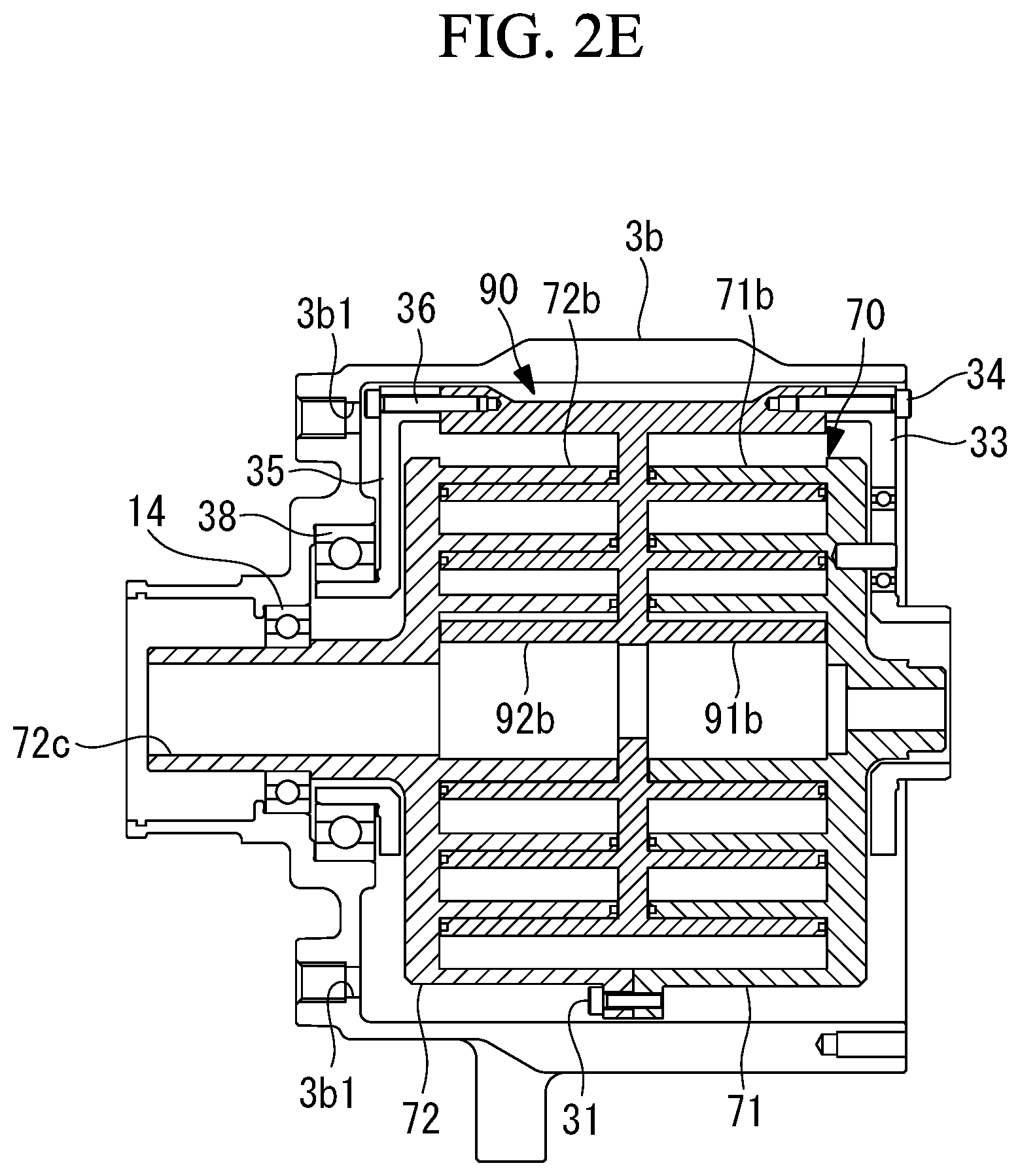
[0010] The hole may also be used for access to the reference pin or positioning pin of each component incorporated in the housing, or for passing a stopper to prevent rotation of the scroll member during assembly, as another application.
[0011] Further, the co-rotating scroll compressor according to one aspect of the present disclosure includes a sealing body that seals the hole.
[0012] The sealing body is attached to the hole and sealed after the work is performed using the hole. Therefore, the housing can be closely sealed.
[0013] Further, in the co-rotating scroll compressor according to one aspect of the present disclosure, a plurality of the holes are provided.
[0014] Multiple holes are formed. This enables various works to be performed at desired positions.
[0015] Further, in the co-rotating scroll compressor according to one aspect of the present disclosure, the hole is provided at end part opposite to the end part that is openable of the housing.
[0016] When the end part of the housing is openable, each component may be inserted into the housing from the openable end part during assembly. However, it may be necessary to access each component after each component is inserted into the housing and assembled in the housing. Therefore, providing a hole at the end part opposite to the openable end part enables access to each component assembled in the housing.
[0017] Further, a method of assembling a co-rotating scroll compressor according to an aspect of the present disclosure, the co-rotating scroll compressor including: a driving-side scroll member that is rotationally driven by a driving unit and includes a spiral driving-side wall disposed on a driving-side end plate; a driven-side scroll member that includes a driven-side wall corresponding to the driving-side wall, the driven-side wall being disposed on a driven-side end plate and engaging with the driving-side wall to form a compression space; a synchronous driving mechanism that transmits driving force from the driving-side scroll member to the driven-side scroll member to cause the driving-side scroll member and the driven-side scroll member to perform rotational movement in a same direction at a same angular velocity; and a housing accommodating the driving-side scroll member, the driven-side scroll member and the synchronous driving mechanism, in which the driving-side scroll member includes a first driving-side scroll portion, a second driving-side scroll portion, and a wall fixing part, the first driving-side scroll portion including a first driving-side end plate and a first driving-side wall and being driven by the driving unit, the second driving-side scroll portion including a second driving-side end plate and a second driving-side wall, and the wall fixing part performing fixing while a front end in an axial direction of the first driving-side wall and a front end in an axial direction of the second driving-side wall face each other, and the driven-side scroll member includes a first driven-side wall and a second driven-side wall, the first driven-side wall being provided on one side surface of the driven-side end plate and engaging with the first driving-side wall, and the second driven-side wall being provided on another side surface of the driven-side end plate and engaging with the second driving-side wall, in which the co-rotating scroll compressor includes a first support member and a second support member, the first support member being disposed with the first driving-side end plate interposed therebetween and being fixed by a first support fixing part to the front end side in the axial direction of the first driven-side wall to rotate with the first driven-side wall, and the second support member being disposed with the second driving-side end plate interposed therebetween and being fixed by a second support fixing part to the front end side in the axial direction of the second-driven side wall to rotate with the second driven-side wall, in which the first support fixing part or the second support fixing part is fixed, after the first support member or the second support member is assembled to the housing, using a hole accessible to the first support fixing part or the second support fixing part formed in the housing.
[0018] The housing is formed with the hole that allows access to the first support fixing part or the second support fixing part. A tool can be inserted through the hole accessible to the first support fixing part or the second support fixing part. Thus, after the support member is incorporated into the housing, access can be performed from the outside of the housing, and the complexity of the assembly process can be reduced.
[0019] Further, a method of assembling a co-rotating scroll compressor according to an aspect of the present disclosure, the co-rotating scroll compressor including: a driving-side scroll member that is rotationally driven by a driving unit and includes a spiral driving-side wall disposed on a driving-side end plate; a driven-side scroll member that includes a driven-side wall corresponding to the driving-side wall, the driven-side wall being disposed on a driven-side end plate and engaging with the driving-side wall to form a compression space; a synchronous driving mechanism that transmits driving force from the driving-side scroll member to the driven-side scroll member to cause the driving-side scroll member and the driven-side scroll member to perform rotational movement in a same direction at a same angular velocity; and a housing accommodating the driving-side scroll member, the driven-side scroll member and the synchronous driving mechanism, in which the driving-side scroll member includes a first driving-side scroll portion, a second driving-side scroll portion, and a wall fixing part, the first driving-side scroll portion including a first driving-side end plate and a first driving-side wall and being driven by the driving unit, the second driving-side scroll portion including a second driving-side end plate and a second driving-side wall, and the wall fixing part performing fixing while a front end in an axial direction of the first driving-side wall and a front end in an axial direction of the second driving-side wall face each other, and the driven-side scroll member includes a first driven-side wall and a second driven-side wall, the first driven-side wall being provided on one side surface of the driven-side end plate and engaging with the first driving-side wall, and the second driven-side wall being provided on another side surface of the driven-side end plate and engaging with the second driving-side wall, in which the co-rotating scroll compressor includes a first support member and a second support member, the first support member being disposed with the first driving-side end plate interposed therebetween and being fixed by a first support fixing part to the front end side in the axial direction of the first driven-side wall body to rotate with the first driven-side wall, and the second support member being disposed with the second driving-side end plate interposed therebetween and being fixed by a second support fixing part to the front end side in the axial direction of the second-driven side wall to rotate with the second driven-side wall, in which the wall fixing part is fixed, after the first driving-side scroll portion or the second driving-side scroll portion are assembled to the housing, using a hole accessible to the wall fixing part formed in the housing.
[0020] The housing is formed with the hole accessible to the wall fixing part. A tool can be inserted through this hole to access to the wall fixing part. As a result, after the driving-side scroll member is incorporated into the housing, access can be performed from the outside of the housing, and the complexity of the assembly process can be reduced.
[0021] In addition, an assembling method of the co-rotating scroll compressor as a reference example, the co-rotating scroll compressor including: a driving-side scroll member that is rotationally driven by a driving unit and includes a spiral driving-side wall disposed on a driving-side end plate; a driven-side scroll member that includes a driven-side wall corresponding to the driving-side wall, the driven-side wall being disposed on a driven-side end plate and engaging with the driving-side wall to form a compression space; a synchronous driving mechanism that transmits driving force from the driving-side scroll member to the driven-side scroll member to cause the driving-side scroll member and the driven-side scroll member to perform rotational movement in a same direction at a same angular velocity; and a housing accommodating the driving-side scroll member, the driven-side scroll member and the synchronous driving mechanism, in which the driving-side scroll member includes a first driving-side scroll portion, a second driving-side scroll portion, and a wall fixing part, the first driving-side scroll portion including a first driving-side end plate and a first driving-side wall and being driven by the driving unit, the second driving-side scroll portion including a second driving-side end plate and a second driving-side wall, and the wall fixing part performing fixing while a front end in an axial direction of the first driving-side wall and a front end in an axial direction of the second driving-side wall face each other, and the driven-side scroll member includes a first driven-side wall and a second driven-side wall, the first driven-side wall being provided on one side surface of the driven-side end plate and engaging with the first driving-side wall, and the second driven-side wall being provided on another side surface of the driven-side end plate and engaging with the second driving-side wall, in which the co-rotating scroll compressor includes a first support member and a second support member, the first support member being disposed with the first driving-side end plate interposed therebetween and being fixed by a first support fixing part to the front end side in the axial direction of the first driven-side wall to rotate with the first driven-side wall, and the second support member being disposed with the second driving-side end plate interposed therebetween and being fixed by a second support fixing part to the front end side in the axial direction of the second-driven side wall to rotate with the second driven-side wall, in which after the first driving-side scroll portion and the second driving-side scroll portion, the first support member and the second support member are integrated to form an assembly, the assembly is assembled to the housing.
[0022] Before being inserted into the housing, the first driving-side scroll portion and the second driving-side scroll portion, the first support member and the second support member are integrated to form an assembly. Thus, centering of both scroll members can be performed before being incorporated into the housing, so that both scroll members can be accurately assembled. In addition, the hole and the sealing body described above become unnecessary, and the number of parts can be reduced.
Advantageous Effects of Invention
[0023] A hole is provided in the housing to allow access to the driving-side scroll member and the support member. This can facilitate assembly.
BRIEF DESCRIPTION OF DRAWINGS
[0024] FIG. 1 is a longitudinal sectional view showing a co-rotating scroll compressor according to an embodiment of the present disclosure.
[0025] FIG. 2A is a longitudinal sectional view showing a first process of an assembly of the co-rotating scroll compressor of FIG. 1.
[0026] FIG. 2B is a longitudinal sectional view showing a second process of the assembly of the co-rotating scroll compressor of FIG. 1.
[0027] FIG. 2C is a longitudinal sectional view showing a third process of the assembly of the co-rotating scroll compressor of FIG. 1.
[0028] FIG. 2D is a longitudinal sectional view showing a fourth process of the assembly of the co-rotating scroll compressor of FIG. 1.
[0029] FIG. 2E is a longitudinal sectional view showing a fifth process of the assembly of the co-rotating scroll compressor of FIG. 1.
[0030] FIG. 3A is a longitudinal cross-sectional view showing a first process of assembly of the co-rotating scroll compressor according to the reference embodiment.
[0031] FIG. 3B is a longitudinal cross-sectional view showing a second process of the assembly of the co-rotating scroll compressor according to the reference embodiment.
DESCRIPTION OF EMBODIMENTS
[0032] An embodiment of the present disclosure is described below with reference to FIG. 1 and FIG. 2.
[0033] FIG. 1 illustrates a co-rotating scroll compressor (scroll compressor) 1. The co-rotating scroll compressor 1 can be used as, for example, a supercharger that compresses combustion air (fluid) to be supplied to an internal combustion engine such as a vehicle engine.
[0034] The co-rotating scroll compressor 1 includes a housing 3, a motor (driving unit) 5 accommodated on one end side in the housing 3, and a driving-side scroll member 70 and a driven-side scroll member 90 that are accommodated on the other end side in the housing 3.
[0035] The housing 3 has a substantially cylindrical shape, and includes a motor accommodation portion 3a that accommodates the motor 5, and a scroll accommodation portion 3b that accommodates the scroll members 70 and 90.
[0036] A cooling fin 3c to cool the motor 5 is provided on an outer periphery of the motor accommodation portion 3a. A discharge opening 3d from which compressed air (working fluid) is discharged is provided at an end part of the scroll accommodation portion 3b. Note that, although not illustrated in FIG. 1, the housing 3 includes an air suction opening from which air (working fluid) is sucked in. Further, an access hole 3b1 that is a through hole is formed at an end part of the scroll accommodation portion 3b. The plurality of access holes 3b1 are provided, and are formed in accordance with the position of the object to be accessed. The number of access holes 3b1 may be one.
[0037] A sealing bolt (sealing body) 40 for sealing is provided in the access hole 3b1. The sealing bolt 40 is attached after the assembly is completed. In addition, when it is not necessary to seal the inside of the housing 3, the sealing bolt 40 may be omitted. In this case, the through hole by the access hole 3b1 remains open.
[0038] The motor 5 is driven by being supplied with power from an unillustrated power supply source. Rotation of the motor 5 is controlled by an instruction from an unillustrated control unit. A stator 5a of the motor 5 is fixed to an inner periphery of the housing 3. A rotor 5b of the motor 5 rotates around a driving-side rotation axis CL1. A driving shaft 6 that extends on the driving-side rotation axis CL1 is connected to the rotor 5b. The driving shaft 6 is connected to a first driving-side shaft portion 7c of the driving-side scroll member 70.
[0039] The driving-side scroll member 70 includes a first driving-side scroll portion 71 on the motor 5 side, and a second driving-side scroll portion 72 on the discharge opening 3d side.
[0040] The first driving-side scroll portion 71 includes a first driving-side end plate 71a and first driving-side walls 71b.
[0041] The first driving-side end plate 71a is connected to the first driving-side shaft portion 7c connected to the driving shaft 6, and extends in a direction orthogonal to the driving-side rotation axis CL1. The first driving-side shaft portion 7c is provided so as to be rotatable with respect to the housing 3 through a first driving-side bearing 11 that is a ball bearing.
[0042] The first driving-side end plate 71a has a substantially disc shape in a planar view. The plurality of first driving-side walls 71b formed in a spiral shape are provided on the first driving-side end plate 71a. The first driving-side walls 71b are disposed at an equal interval around the driving-side rotation axis CL1.
[0043] The second driving-side scroll portion 72 includes a second driving-side end plate 72a and a second driving-side walls 72b. The plurality of second driving-side walls 72b each formed in a spiral shape are provided similarly to the above-described first driving-side walls 71b.
[0044] A second driving-side shaft portion 72c in a cylindrical shape that extends in the driving-side rotation axis CL1 is connected to the second driving-side end plate 72a. The second driving-side shaft portion 72c is provided so as to be rotatable with respect to the housing 3 through a second driving-side bearing 14 that is a ball bearing. The second driving-side end plate 72a includes a discharge port 72d extending along the driving-side rotation axis CL1.
[0045] Two seal members 16 are provided on a front end side (left side in FIG. 1) of the second driving-side shaft portion 72c relative to the second driving-side bearing 14, between the second driving-side shaft portion 72c and the housing 3. The two seal members 16 and the second driving-side bearing 14 are disposed to include a predetermined interval in the driving side rotation axis CL1 direction. For example, a lubricant that is a grease as a semi-solid lubricant is sealed between the two seal members 16. Note that only one seal member 16 may be provided. In this case, the lubricant is sealed between the seal member 16 and the second driving-side bearing 14.
[0046] The first driving-side scroll portion 71 and the second driving-side scroll portion 72 are fixed while the front ends (free ends) of the walls 71b and 72b face each other. The first driving-side scroll portion 71 and the second driving-side scroll portion 72 are fixed by wall fixing bolts (wall fixing parts) 31 that are fastened to flange portions 73 provided at a plurality of positions in the circumferential direction. The flange portions 73 are provided so as to protrude outward in the radial direction. The wall fixing bolt 31 is in a position accessible by a tool from the access hole 3b1 formed in the scroll accommodation portion 3b.
[0047] The driven-side scroll member 90 includes a driven-side end plate 90a that is located at a substantially center in the axial direction (horizontal direction in figure). The through hole 90h is provided at a center of the driven-side end plate 90a, and causes the compressed air to flow toward the discharge port 72d.
[0048] A first driven-side walls 91b are provided on one side surface of the driven-side end plate 90a, and a second driven-side walls 92b are provided on the other side surface of the driven-side end plate 90a. The first driven-side walls 91b provided on the motor 5 side from the driven-side end plate 90a engage with the first driving-side walls 71b of the first driving-side scroll portion 71. The second driven-side walls 92b provided on the discharge opening 3d side from the driven-side end plate 90a engage with the second driving-side walls 72b of the second driving-side scroll portion 72.
[0049] A first support member 33 and a second support member 35 are provided at both ends of the driven-side scroll member 90 in the axial direction (horizontal direction in the figure). The first support member 33 is disposed on the motor 5 side, and the second support member 35 is disposed on the discharge opening 3d side.
[0050] The first support member 33 is fixed to the front ends (free ends) on the outer peripheral side of the first driven-side walls 91b by a first support fixing bolt (first support fixing part) 34, and a second support member 35 is fixed to the front ends (free ends) on the outer peripheral side of the second driven-side walls 92b by a second support fixing bolt (second support fixing part) 36. The second support fixing bolt 36 is in a position accessible by a tool from the access hole 3b1 formed in the scroll housing 3b.
[0051] A shaft portion 33a is provided on the center axis side of the first support member 33, and the shaft portion 33a is fixed to the housing 3 through a first support member bearing 37. A shaft portion 35a is provided on the center axis side of the second support member 35, and the shaft portion 35a is fixed to the housing 3 through a second support member bearing 38. As a result, the driven-side scroll member 90 rotates around a driven-side center axis CL2 through the support members 33 and 35.
[0052] A pin-ring mechanism (synchronous driving mechanism) 15 is provided between the first support member 33 and the first driving-side end plate 71a. More specifically, a rolling bearing (ring) is provided in the first driving-side end plate 71a, and a pin member 15b is provided on the first support member 33. The pin-ring mechanism 15 transmits the driving force from the driving-side scroll member 70 to the driven-side scroll member 90, and causes the scroll members 70 and 90 to perform rotational movement in the same direction at the same angular velocity.
[0053] The co-rotating scroll compressor 1 including the above-described configuration operates in the following manner.
[0054] When the driving shaft 6 rotates around the driving-side rotation axis CL1 by the motor 5, the first driving-side shaft portion 7c connected to the driving shaft 6 also rotates, and the driving-side scroll member 70 accordingly rotates around the driving-side rotation axis CL1. When the driving-side scroll member 70 rotates, the driving force is transmitted from the support members 33 and 35 to the driven-side scroll member 90 through the pin-ring mechanisms 15, and the driven-side scroll member 90 rotates around the driven-side rotation axis CL2. At this time, when the pin members 15b of the pin-ring mechanisms 15 move while being in contact with the inner periphery surface of the circular hole, the both scroll members 70 and 90 perform rotational movement at the same angular velocity in the same direction.
[0055] When the scroll members 70 and 90 perform oscillating revolving movement, the air sucked through the air suction. opening of the housing 3 is sucked in from the outer peripheral side of each of the scroll members 70 and 90, and is taken into compression chambers formed by the scroll members 70 and 90. Further, compression is separately performed in compression chambers formed by the first driving-side walls 71b and the first driven-side walls 91b and in compression chambers formed by the second driving-side walls 72b and the second driven-side walls 92b. A volume of each of the compression chambers is reduced as each of the compression chambers moves toward the center, which compresses the air. The air compressed by the first driving-side walls 71b and the first driven-side walls 91b passes through the through hole 90h provided in the driven-side end plate 90a, and is joined with the air compressed by the second driving-side walls 72b and the second driven-side walls 92b. The resultant air passes through the discharge port 72d and is discharged to outside from the discharge opening 3d of the housing 3. The discharged compressed air is guided to an unillustrated internal combustion engine, and is used as combustion air.
Assembly Method
[0056] Next, referring to FIGS. 2A to 2E, a method of assembling the co-rotating scroll compressor 1 is described.
[0057] First, as shown in FIG. 2A, after the second driving-side bearing 14 and the second support member bearing 38 are attached to the scroll accommodation portion 3b, the second support member 35 is inserted from the open end side of the scroll accommodation portion 3b and assembled. Specifically, the shaft portion 35a of the second support member 35 is inserted into the inner periphery of the inner ring of the second support member bearing 38. At this time, the sealing bolt 40 (see FIG. 1) is not attached to the access hole 3b1 formed in the scroll accommodation portion 3b.
[0058] Next, as shown in FIG. 2B, the second driving-side scroll portion 72 is assembled. Specifically, the second driving-side shaft portion 72c of the second driving-side scroll portion 72 is inserted into the inner periphery of the inner ring of the second driving-side bearing 14.
[0059] Then, as shown in FIG. 2C, the driven-side scroll member 90 is assembled. Specifically, after the front end of the second driven-side wall 92b of the driven-side scroll member 90 and the front end of the second support member 35 are butted, the driven-side scroll member 90 and the second support member 35 are fixed using the second support fixing bolt 36. This fixing work is performed by inserting a tool from the access hole 3b1 and rotating the second support fixing bolt 36 about its axis. When the second support fixing bolt 36 is fixed at a plurality of positions, the fixing work may be performed by rotating the driven-side scroll member 90 and the second support member 35 by a predetermined angle using the same access hole 3b1 or the fixing work may be performed using a plurality of access holes 3b1 provided at corresponding angular positions without the driven-side scroll member 90 and the second support member 35 being rotated.
[0060] Then, as shown in FIG. 2D, the first driving-side scroll portion 71 is assembled. Specifically, after the first driving-side wall 71b is butted to the second driving-side wall 72b of the second driving-side scroll portion 72, the first driving-side scroll portion 71 and the second driving-side scroll portion 72 are fixed using the wall fixing bolt 31. This fixing work is performed by inserting a tool from the access hole 3b1 and rotating the wall fixing bolt 31 about its axis. When the wall fixing bolt 31 is fixed at a plurality of positions, the fixing work may be performed by rotating the driving-side scroll member 70 by a predetermined angle using the same access hole 3b1, or the fixing work may be performed using a plurality of access holes 3b1 provided at corresponding angular positions without the driving-side scroll member 70 being rotated.
[0061] Then, as shown in FIG. 2E, the first support member 33 is assembled. Specifically, after the front end of the first driven-side wall 91b of the driven-side scroll member 90 and the front end of the first support member 33 are abutted, the driven-side scroll member 90 and the first support member 33 are fixed using the first support fixing bolt 34. This fixing work is performed by accessing from the open end (right side end part in the same Figure) side of the scroll accommodation portion 3b.
[0062] Then, the sealing bolt 40 is fixed to the access hole 3b1. Thereby, the inside of the housing 3 can be closely sealed.
[0063] The fixing work of the second support fixing bolt 36 described with reference to FIG. 2C may be performed after the driven-side scroll member 90 is temporarily fixed to the second support member 35, and may be performed after the process of FIG. 2D or FIG. 2E, for example.
[0064] Further, the fixing work of the wall fixing bolt 31 described with reference to FIG. 2D may be performed by accessing from the open end side of the scroll accommodation portion 3b without using the access hole 3b1.
[0065] The present embodiment achieves the following action effects.
[0066] A tool can be inserted through the access hole 3b1 to access the second support fixing bolt 36 and the wall fixing bolt 31. As a result, after the second support member 35 and the driving-side scroll member 70 are incorporated into the scroll accommodation portion 3b, access can be performed from the outside of the housing 3, and work can be performed, which facilitates assembly work.
[0067] After working using the access hole 3b1, the sealing bolt 40 is attached to the access hole 3b1 and sealed. This allows the housing 3 to be closely sealed.
[0068] The access hole 3b1 is provided at the end part opposite to the end part openable of the scroll accommodation portion 3b. Therefore, the second support member 35 and the driving-side scroll member 70 can be accessed after being assembled in the scroll accommodation portion 3b.
[0069] In the embodiment described above, although the co-rotating scroll compressor is used as the supercharger, the present disclosure is not limited to this, and it is possible to widely use it as long as it compresses fluid. It can also be used, for example, as a refrigerant compressor used in air conditioning machines. Moreover, it is also possible to apply the scroll compressor 1 of the invention to the air control apparatus using air force as a brake system for rail vehicles.
[0070] Also, the access hole 3b1 can also be used for accessing the reference pins and positioning pins of each component incorporated in the scroll accommodation portion 3b or passing a stopper to prevent the scroll members 70 and 90 from rotating during assembly as another application.
Reference Embodiment
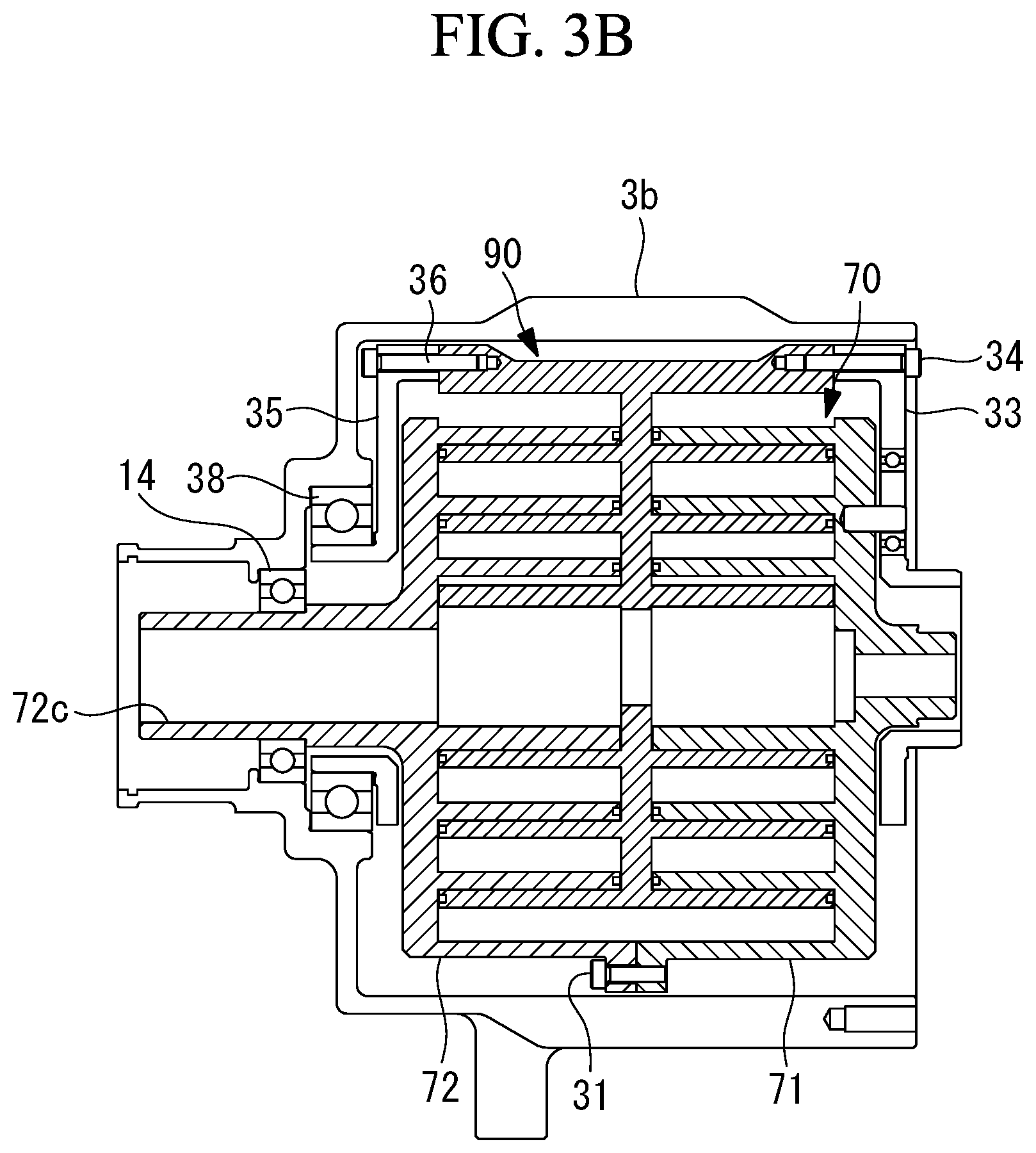
[0071] Reference embodiments are shown in FIGS. 3A and 3B.
[0072] If the scroll accommodation portion 3b is not provided with the access hole 3b1 (see FIG. 1), the assembly is performed as follows. That is, as shown in FIG. 3A and FIG. 3B, the first driving-side scroll portion 71 and the second driving-side scroll portion 72 are fixed by the wall fixing bolt 31, and the first support member 33 and the driven-side scroll member 90 are fixed by the first support fixing bolt 34, and, the second support member 35 and the driven-side scroll member 90 are fixed by the second support fixing bolt 36, then these are integrated to form a cartridge (assembly). Thereafter, the cartridge is inserted from the open end side of the scroll accommodation portion 3b and assembled.
[0073] The cartridge is formed before being inserted into the scroll accommodation portion 3b, which allows both scroll members 70 and 90 to be centered before the cartridge is inserted into the scroll accommodation portion 3b. Therefore, the both scroll members 70 and 90 can be accurately assembled. Further, the access hole 3b1 and the sealing bolt 40 described above become unnecessary, and the number of parts can be reduced.
REFERENCE SIGNS LIST
[0074] 1 Co-rotating scroll compressor (scroll compressor) [0075] 3 Housing [0076] 3a Motor accommodation portion [0077] 3b Scroll accommodation portion (housing) [0078] 3b1 Access hole [0079] 3c Cooling fins [0080] 3d Discharge opening [0081] 5 Motor (driving unit) [0082] 5a Stator [0083] 5b Rotor [0084] 6 Driving shaft [0085] 7c First driving-side shaft portion [0086] 11 First driving-side bearing [0087] 14 Second driving-side bearing [0088] 15 Pin-ring mechanism (synchronous driving mechanism) [0089] 15b Pin member [0090] 16 Seal member [0091] 31 Wall fixing bolt (wall fixing part) [0092] 33 First support member [0093] 33a Shaft portion [0094] 34 First support fixing bolt (first support fixing portion) [0095] 35 Second support member [0096] 35a Shaft portion [0097] 36 Second support fixing bolt (second support fixing portion) [0098] 37 First support member bearing [0099] 38 Second support member bearing [0100] 40 Sealing bolt (sealed body) [0101] 70 Driving-side scroll member [0102] 71 First driving-side scroll portion [0103] 71a First driving-side end plate [0104] 71b First driving-side wall [0105] 72 Second driving-side scroll portion [0106] 72a Second driving-side end plate [0107] 72b Second driving-side wall [0108] 72c Second driving-side shaft portion [0109] 72d Discharge port [0110] 73 Flange portion [0111] 90 Driven-side scroll member [0112] 90a Driven-side end plate [0113] 90h Through hole [0114] 91b First driven-side wall [0115] 92b Second driven-side wall [0116] CL1 Driving-side rotation axis [0117] CL2 Driven-side rotation axis
* * * * *
D00000
D00001
D00002
D00003
D00004
D00005
D00006
XML
uspto.report is an independent third-party trademark research tool that is not affiliated, endorsed, or sponsored by the United States Patent and Trademark Office (USPTO) or any other governmental organization. The information provided by uspto.report is based on publicly available data at the time of writing and is intended for informational purposes only.
While we strive to provide accurate and up-to-date information, we do not guarantee the accuracy, completeness, reliability, or suitability of the information displayed on this site. The use of this site is at your own risk. Any reliance you place on such information is therefore strictly at your own risk.
All official trademark data, including owner information, should be verified by visiting the official USPTO website at www.uspto.gov. This site is not intended to replace professional legal advice and should not be used as a substitute for consulting with a legal professional who is knowledgeable about trademark law.