Structurally Reinforced Tent Frame And Central Reinforcing Structure Thereof
SUN; Yuanru ; et al.
U.S. patent application number 16/261538 was filed with the patent office on 2019-12-05 for structurally reinforced tent frame and central reinforcing structure thereof. This patent application is currently assigned to ZHEJIANG JIANSHENG LEISURE PRODUCTS CO.,LTD. The applicant listed for this patent is ZHEJIANG JIANSHENG LEISURE PRODUCTS CO., LTD. Invention is credited to Jian HE, Yuanru SUN.
| Application Number | 20190368220 16/261538 |
| Document ID | / |
| Family ID | 66655531 |
| Filed Date | 2019-12-05 |

| United States Patent Application | 20190368220 |
| Kind Code | A1 |
| SUN; Yuanru ; et al. | December 5, 2019 |
STRUCTURALLY REINFORCED TENT FRAME AND CENTRAL REINFORCING STRUCTURE THEREOF
Abstract
A structurally reinforced tent frame includes standing poles that each have a connecting base and a slidable base are disposed thereon. A first tarpaulin supporting pole has one end hinged on the connecting base and another end hinged with a top plate. An auxiliary supporting pole has one end hinged on the first tarpaulin supporting pole and another end hinged with the slidable base. A hinged crossbeam is disposed between adjacent standing poles and has ends connected with the connecting bases and the slidable bases. A second tarpaulin supporting pole has one end hinged with a hinge point of the hinged crossbeam and another end hinged with the top plate. Four second tarpaulin supporting poles and two first tarpaulin supporting poles are connected to supporting poles. Other ends of the supporting poles are hinged with a lower plate. A retractable position-limiting pole is disposed between the lower plate and the top plate.
| Inventors: | SUN; Yuanru; (Zhejiang, CN) ; HE; Jian; (Zhejiang, CN) | ||||||||||
| Applicant: |
|
||||||||||
|---|---|---|---|---|---|---|---|---|---|---|---|
| Assignee: | ZHEJIANG JIANSHENG LEISURE PRODUCTS
CO.,LTD Zhejiang CN |
||||||||||
| Family ID: | 66655531 | ||||||||||
| Appl. No.: | 16/261538 | ||||||||||
| Filed: | January 29, 2019 |
| Current U.S. Class: | 1/1 |
| Current CPC Class: | E04H 15/18 20130101; E04H 15/46 20130101; E04H 15/50 20130101 |
| International Class: | E04H 15/46 20060101 E04H015/46; E04H 15/50 20060101 E04H015/50 |
Foreign Application Data
| Date | Code | Application Number |
|---|---|---|
| May 29, 2018 | CN | 201810529337.X |
| May 29, 2018 | CN | 201820811854.1 |
Claims
1. A structurally reinforced tent frame, comprising four standing poles, wherein a connecting base and a slidable base are disposed on each of the standing poles, one end of a first tarpaulin supporting pole is hinged on the connecting base, another end of the first tarpaulin supporting pole is hinged with a top plate, one end of an auxiliary supporting pole is hinged on the first tarpaulin supporting pole, another end of the auxiliary supporting pole is hinged with the slidable base, a hinged crossbeam is disposed between adjacent standing poles, ends of the hinged crossbeam are respectively connected with the connecting bases and the slidable bases on the standing poles, a hinge point of the hinged crossbeam is hinged with a second tarpaulin supporting pole, another end of the second tarpaulin supporting pole is hinged with the top plate, wherein a number of the first tarpaulin supporting pole and the second tarpaulin supporting pole are both four, the four second tarpaulin supporting poles and any two first tarpaulin supporting poles that are arranged on a diagonally are connected to supporting poles, other ends of the supporting poles are hinged with a lower plate, and a retractable position-limiting pole is disposed between the lower plate and the top plate.
2. The structurally reinforced tent frame as claimed in claim 1, wherein the retractable position-limiting pole comprises a first position-limiting pole fixed with the top plate and a second position-limiting pole fixed with the lower plate, the second position-limiting pole is sleeved to exterior of the first position-limiting pole, and the first position-limiting pole is movable inside the second position-limiting pole in an up-down direction.
3. The structurally reinforced tent frame as claimed in claim 1, wherein the retractable position-limiting pole comprises a first position-limiting pole fixed with the top plate and a second position-limiting pole fixed with the lower plate, the first position-limiting pole is sleeved to exterior of the second position-limiting pole and the second position-limiting pole is movable inside the first position-limiting pole in an up down direction.
4. The structurally reinforced tent frame as claimed in claim 2, wherein the first position-limiting pole or the second position-limiting pole has a multi-segment retractable pole structure.
5. The structurally reinforced tent frame as claimed in claim 3, wherein the first position-limiting pole or the second position-limiting pole has a multi-segment retractable pole structure.
6. The structurally reinforced tent frame as claimed in claim 2, wherein a position-limiting structure that prevents the second position-limiting pole from being detached from the first position-limiting pole is disposed on a bottom portion of the first position-limiting pole or a top portion of the second position-limiting pole.
7. The structurally reinforced tent frame as claimed in claim 3, wherein a position-limiting structure that prevents the second position-limiting pole from being detached from the first position-limiting pole is disposed on a bottom portion of the first position-limiting pole or a top portion of the second position-limiting pole.
8. A central reinforcing structure for a structurally reinforced tent frame, comprising first tarpaulin supporting poles, second tarpaulin supporting poles, supporting poles, a top plate, and a lower plate, wherein a number of the first tarpaulin supporting poles and the second tarpaulin supporting poles are both four, the first tarpaulin supporting poles and the second tarpaulin supporting poles are hinged and fit with the top plate, the four second tarpaulin supporting poles and any two symmetrically arranged first tarpaulin supporting poles are connected with the supporting poles, other ends of the supporting poles are hinged with the lower plate, and a retractable position-limiting pole is disposed between the lower plate and the top plate.
9. The central reinforcing structure for the structurally reinforced tent frame as claimed in claim 8, wherein the retractable position-limiting pole comprises a first position-limiting pole fixed with the top plate and a second position-limiting pole fixed with the lower plate, the second position-limiting pole is sleeved to exterior of the first position-limiting pole, and the first position-limiting pole is movable inside the second position-limiting pole in an up-down direction.
10. The central reinforcing structure for the structurally reinforced tent frame as claimed in claim 8, wherein the retractable position-limiting pole comprises a first position-limiting pole fixed with the top plate and a second position-limiting pole fixed with the lower plate, the first position-limiting pole is sleeved to exterior of the second position-limiting pole, and the second position-limiting pole is movable inside the first position-limiting pole in an upper-lower direction.
11. The central reinforcing structure for the structurally reinforced tent frame as claimed in claim 9, wherein the first position-limiting pole or the second position-limiting pole has a multi-segment retractable pole structure.
12. The central reinforcing structure for the structurally reinforced tent frame as claimed in claim 10, wherein the first position-limiting pole or the second position-limiting pole has a multi-segment retractable pole structure.
13. The central reinforcing structure for the structurally reinforced tent frame as claimed in claim 9, wherein a position-limiting structure that prevents the second position-limiting pole from being detached from the first position-limiting pole is disposed on a bottom portion of the first position-limiting pole or a top portion of the second position-limiting pole.
14. The central reinforcing structure for the structurally reinforced tent frame as claimed in claim 10, wherein a position-limiting structure that prevents the second position-limiting pole from being detached from the first position-limiting pole is disposed on a bottom portion of the first position-limiting pole or a top portion of the second position-limiting pole.
Description
CROSS-REFERENCE TO RELATED APPLICATION
[0001] This application claims the priority benefits of Chinese application serial no. 201810529337.X, filed on May 29, 2018, and Chinese application serial no. 201820811854.1, filed on May 29, 2018. The entirety of each of the above-mentioned patent applications is hereby incorporated by reference herein and made a part of specification.
BACKGROUND OF THE INVENTION
1. Field of the Invention
[0002] The invention relates to a tent, and particularly relates to a structurally reinforced tent frame and a central reinforcing structure thereof.
2. Description of Related Art
[0003] Tents/Canopies are outdoor products commonly used in daily activities of people. A tent/canopy usually includes a support frame and a tarpaulin. In order to be carried around easily, the support frame is commonly designed to have a foldable frame structure.
[0004] Chinese Utility Model Patent No. CN205918220U discloses a canopy frame for alleviating standing water, which includes foot poles, hinged crossbeams, frame supporting poles, and a top plate. The foot poles are vertically arranged. A bottom portion of the foot pole stands on the ground, a top portion of the foot pole is hinged with one end of the frame supporting pole, and another end of the frame supporting pole is connected with the top plate. Top portions of two adjacent foot poles are connected by the hinged crossbeam. In addition, the canopy frame is characterized in further including pull rods and a top plate supporting pole assembly. One end of the pull rod is hinged with the top plate, the other end of the pull rod is hinged with a hinge point of the hinged crossbeam. Moreover, the top plate supporting pole assembly is located below the top plate and is respectively hinged with each of the frame supporting poles and each of the pull rods. According to the specification and drawings of CN205918220U, a base plate of the canopy is connected with the pull rods and the frame supporting poles. If the above structure is adopted, since each of the pull rods and each of the frame supporting poles need to be connected with the base plate when the canopy is being installed, the base plate may be too thin and weak, which makes the canopy frame unstable. Also, the installation structure is complicated, which makes it difficult for installation and maintenance to take place.
SUMMARY OF THE INVENTION
[0005] In view of the above, the invention provides a technical solution with a structurally reinforced tent frame and a central reinforcing structure thereof.
[0006] An embodiment of the invention provides a structurally reinforced tent frame. The structurally reinforced tent frame includes four standing poles. A connecting base and a slidable base are disposed on each of the standing poles. A first tarpaulin supporting pole is hinged on the connecting base. Another end of the first tarpaulin supporting pole is hinged with a top plate. An auxiliary supporting pole is hinged on the first tarpaulin supporting pole. Another end of the auxiliary supporting pole is hinged with the slidable base. A hinged crossbeam is disposed between adjacent standing poles of the standing poles. Ends of the hinged crossbeam are respectively connected with the connecting bases and the slidable bases on the standing poles. A hinge point of the hinged crossbeam is hinged with a second tarpaulin supporting pole. Another end of the second tarpaulin supporting pole is hinged with the top plate. There are four first tarpaulin supporting poles and four second tarpaulin supporting poles. The four second tarpaulin supporting poles and any two first tarpaulin supporting poles that are arranged on a diagonally are connected to supporting poles, other ends of the supporting poles are hinged with a lower plate, and a retractable position-limiting pole is disposed between the lower plate and the top plate.
[0007] According to an embodiment of the invention, in the structurally reinforced tent frame, the retractable position-limiting pole includes a first position-limiting pole fixed with the top plate and a second position-limiting pole fixed with the lower plate, the second position-limiting pole is sleeved to exterior of the first position-limiting pole, and the first position-limiting pole is movable inside the second position-limiting pole in an upper-lower direction.
[0008] According to an embodiment of the invention, in the structurally reinforced tent frame, the retractable position-limiting pole includes a first position-limiting pole fixed with the top plate and a second position-limiting pole fixed with the lower plate, the first position-limiting pole is sleeved to exterior of the second position-limiting pole, and the second position-limiting pole is movable inside the first position-limiting pole in an upper-lower direction.
[0009] According to an embodiment of the invention, in the structurally reinforced tent frame, the first position-limiting pole or the second position-limiting pole has a multi-segment retractable pole structure.
[0010] According to an embodiment of the invention, in the structurally reinforced tent frame, a position-limiting structure that prevents the second position-limiting pole from being detached from the first position-limiting pole is disposed on a bottom portion of the first position-limiting pole or a top portion of the second position-limiting pole.
[0011] An embodiment of the invention provides a central reinforcing structure for a structurally reinforced tent frame. The central reinforcing structure for the structurally reinforced tent includes first tarpaulin supporting poles, second tarpaulin supporting poles, supporting poles, a top plate, and a lower plate. There are four first tarpaulin supporting poles and four second tarpaulin supporting poles. The first tarpaulin supporting poles and the second tarpaulin supporting poles are hinged and fit with the top plate. The four second tarpaulin supporting poles and any two symmetrically arranged first tarpaulin supporting poles are connected with the supporting poles. Other ends of the supporting poles are hinged with the lower plate, and a retractable position-limiting pole is disposed between the lower plate and the top plate.
[0012] According to an embodiment of the invention, in the central reinforcing structure for the structurally reinforced tent frame, the retractable position-limiting pole includes a first position-limiting pole fixed with the top plate and a second position-limiting pole fixed with the lower plate, the second position-limiting pole is sleeved to exterior of the first position-limiting pole, and the first position-limiting pole is movable inside the second position-limiting pole in an upper-lower direction.
[0013] According to an embodiment of the invention, in the central reinforcing structure for the structurally reinforced tent frame, the retractable position-limiting pole includes a first position-limiting pole fixed with the top plate and a second position-limiting pole fixed with the lower plate, the first position-limiting pole is sleeved to exterior of the second position-limiting pole, and the second position-limiting pole is movable inside the first position-limiting pole in an upper-lower direction.
[0014] According to an embodiment of the invention, in the central reinforcing structure for the structurally reinforced tent frame, the first position-limiting pole or the second position-limiting pole has a multi-segment retractable pole structure.
[0015] According to an embodiment of the invention, in central reinforcing structure for the structurally reinforced tent frame, a position-limiting structure that prevents the second position-limiting pole from being detached from the first position-limiting pole is disposed on a bottom portion of the first position-limiting pole or a top portion of the second position-limiting pole.
[0016] Compared with the conventional art, the embodiments of the invention have the following benefits:
[0017] (1) The retractable position-limiting pole disposed between the top plate and the lower plate prevents the top portion of the tent frame from tilting when the tent frame is being folded or unfolded, so the frame is stable.
[0018] (2) The number of connections of the first tarpaulin supporting poles and the second tarpaulin supporting poles on the lower plate is reduced, so the sturdiness of the lower plate is increased. In addition, due to the reduced number of connections of the first tarpaulin supporting poles and the second tarpaulin supporting poles, the gap for installation between the first and second tarpaulin supporting poles is increased. Therefore, the first and second tarpaulin supporting poles can be installed and maintained more easily.
[0019] (3) Since the four second tarpaulin supporting poles are added, the force received by the tarpaulin is more sparsely distributed. Therefore, standing water on the tarpaulin can be effectively alleviated. Besides, with the supportive intervention of the second tarpaulin supporting poles, strength of a side hinge is reinforced.
BRIEF DESCRIPTION OF THE DRAWINGS
[0020] The accompanying drawings are included to provide a further understanding of the invention, and are incorporated in and constitute a part of this specification. The drawings illustrate embodiments of the invention and, together with the description, serve to explain the principles of the invention.
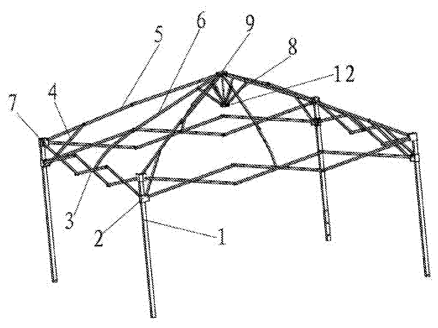
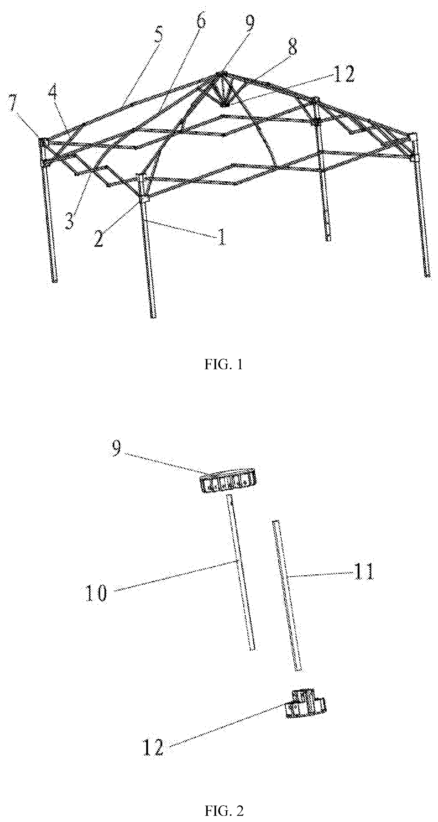
[0021] FIG. 1 is a schematic view illustrating a structure according to an embodiment of the invention.
[0022] FIG. 2 is a schematic exploded view illustrating structures of a lower plate, a retractable position-limiting pole, and a top plate according to an embodiment of the invention.
[0023] FIG. 3 is a schematic view illustrating retracted and extended states of a retractable position-limiting pole according to an embodiment of the invention.
[0024] FIG. 4 is a schematic view illustrating a structure of a retractable position-limiting pole according to another embodiment of the invention.
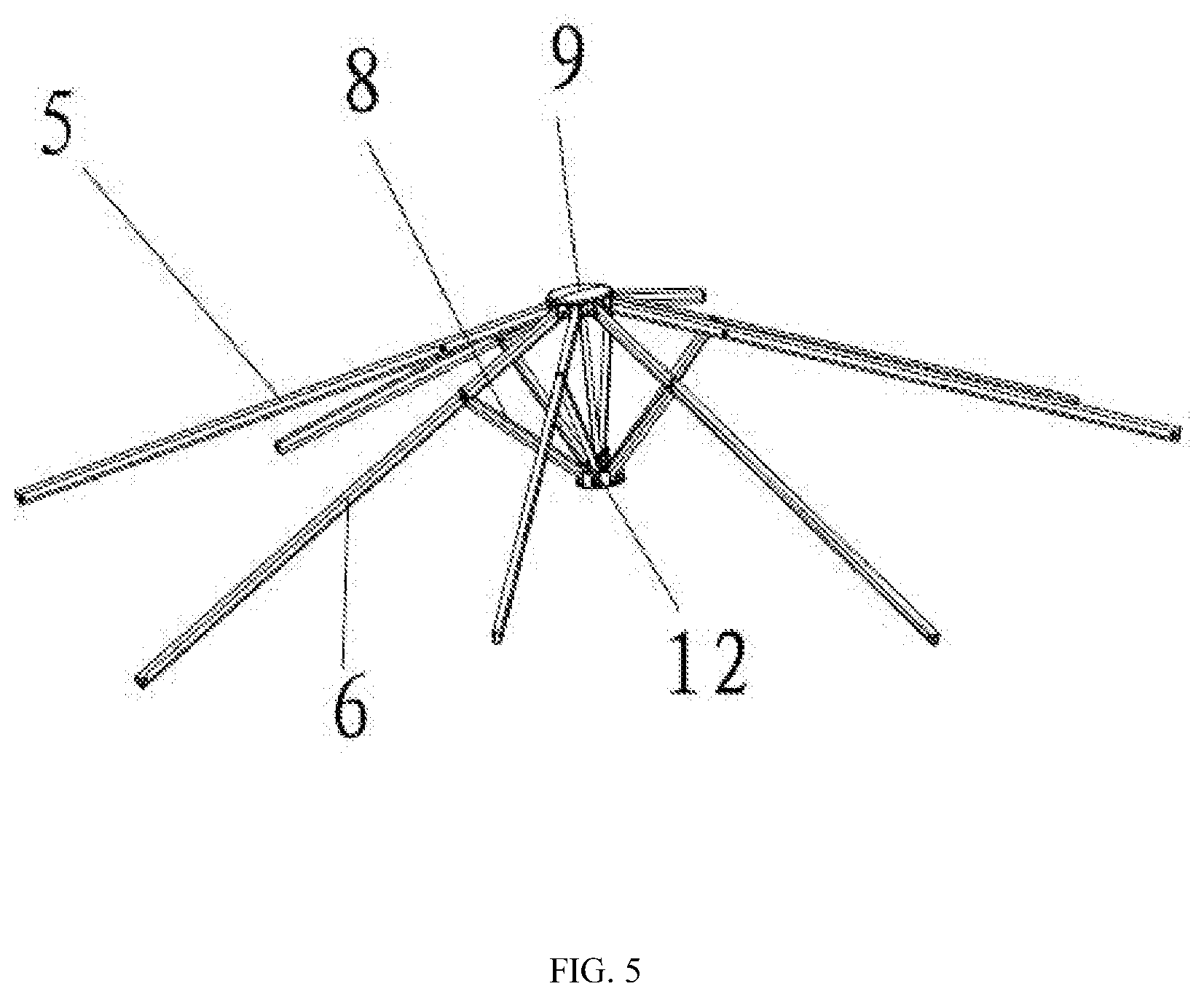
[0025] FIG. 5 is a schematic view illustrating a structure of a central reinforcing structure according to an embodiment of the invention.
DESCRIPTION OF THE EMBODIMENTS
[0026] Reference will now be made in detail to the exemplary embodiments of the invention, examples of which are illustrated in the accompanying drawings. Wherever possible, the same reference numbers are used in the drawings and the description to refer to the same or like parts.
[0027] In the following, the embodiments of the invention will be described in detail with reference to the accompanying drawings.
Embodiment 1
[0028] As shown in FIGS. 1 and 2, a structurally reinforced tent frame includes four standing poles 1. A connecting base 7 and a slidable base 2 are disposed on the standing pole 1. In addition, the connecting base 7 is fixed at the top portion of the standing pole 1, and the slidable base 2 is sleeved to the standing pole 1 and is slidable relative to the standing pole 1. A first tarpaulin supporting pole 5 is hinged on the connecting base 7, and another end of the first tarpaulin supporting pole 5 is hinged with a top plate 9. An auxiliary supporting pole 4 is hinged on the first tarpaulin supporting pole 5, and another end of the auxiliary supporting pole 4 is hinged with the slidable base 2. The first tarpaulin supporting pole 5 is formed by two or more supporting poles hinged with each other. Through sliding of the slidable base 2, the auxiliary supporting pole 4 is driven, so as to drive and fold the first tarpaulin supporting pole 5.
[0029] A hinged crossbeam 3 is disposed between two adjacent standing poles 1. Ends of the crossbeam 3 are respectively connected with the connecting base 7 and the slidable base 2 on the standing poles 1. A hinge point of the hinged crossbeam 3 is hinged with a second tarpaulin supporting pole 6. Another end of the second tarpaulin supporting pole 6 is hinged with a top plate 9. The second tarpaulin supporting pole 6 is formed by two or more supporting poles hinged with each other. Through sliding of the slidable base 2, the hinged crossbeam 3 is driven and folded.
[0030] There are four first tarpaulin supporting pole 5 and four second tarpaulin supporting poles 6. In addition, the four second tarpaulin supporting poles 6 and any two first tarpaulin supporting poles 5 that are arranged on a diagonally are connected to supporting poles 8. Other ends of the supporting poles 8 are hinged with a lower plate 12, and a retractable position-limiting pole is disposed between the lower plate 12 and the top plate 9.
[0031] According to the embodiments of the invention, the directions in which the second tarpaulin supporting poles 6 are opened are controlled by the retractable position-limiting pole, and the force received by the second tarpaulin supporting poles 6 is uniformly fed back to the first tarpaulin supporting poles 5, so that the entire structure is stably supported.
[0032] In one embodiment, the retractable position-limiting pole includes a first position-limiting pole 10 fixed with the top plate 9 and a second position-limiting pole 11 fixed with the lower plate 12. An outer diameter of the first position-limiting pole 10 is smaller than an inner diameter of the second position-limiting pole 11. The second position-limiting pole 11 is sleeved to exterior of the first position-limiting pole 10. In addition, the first position-limiting pole 10 is movable inside the second position-limiting pole 11 in an upper-lower direction.
[0033] In another embodiment, the retractable position-limiting pole includes the first position-limiting pole 10 fixed with the top plate 9 and the second position-limiting pole 11 fixed with the lower plate 12. An inner diameter of the first position-limiting pole 10 is greater than an outer diameter of the second position-limiting pole 11. The first position-limiting pole 10 is sleeved to exterior of the second position-limiting pole 11. In addition, the second position-limiting pole 11 is movable inside the first position-limiting pole 10 in the upper-lower direction.
[0034] As shown in FIG. 3, the two embodiments have the following characteristics.
[0035] Assuming that two ends of the first position-limiting pole 10 are respectively labeled as A and B, and two ends of the second position-limiting pole 11 are respectively labeled as C and D, after installation, the foldable tent is in a completely unfolded state when A and D are in a minimum distance. When the distance between A and D increases, the foldable tent is gradually being folded. After the foldable tent is completely folded, the distance between A and D is the longest in the usage state, and in such a state, the distance between A and D needs to be smaller than a sum of the dimension of A and B and the dimension of C and D, so as to prevent the first position-limiting pole 10 and the second position-limiting pole 11 from being detached from each other. The first position-limiting pole 10 and the second position-limiting pole 11 are added to reinforce the stability between the lower plate 12 and the tarpaulin supporting poles. Only axial movement is allowed between the first position-limiting pole 10 and the second position-limiting pole 11, and radial movement thereof is determined by the size of a gap between the outer diameter of the first position-limiting pole 10 and the inner diameter of the second position-limiting pole 11. In theory, the smaller the gap, the better the position-limiting effect.
[0036] As shown in FIG. 4, based on the two embodiments above, the first position-limiting pole 10 or the second position-limiting pole 11 of the retractable position-limiting pole is configured to have a multi-segment retractable pole structure.
[0037] In the above embodiments, a position-limiting structure that prevents the second position-limiting pole 11 from being detached from the first position-limiting pole 10 is disposed on a bottom portion of the first position-limiting pole 10 or a top portion of the second position-limiting pole 11. The position-limiting structure may be chosen from various known position-limiting structures, such as a position-limiting structure employed in a retractable pole for umbrellas. Position-limiting may be achieved by modifying the structures of the first position-limiting pole 10 and the second position-limiting pole 11, such as modifying the change in the diameters of the first position-limiting pole 10 and the second position-limiting pole 11.
Embodiment 2
[0038] As shown in FIG. 5, another embodiment of the invention provides a central reinforcing structure of a structurally reinforced tent frame. The central reinforcing structure includes the first tarpaulin supporting poles 5, the second tarpaulin supporting poles 6, the supporting poles 8, the top plate 9, and the lower plate 12. There are four first tarpaulin supporting poles 5 and four second tarpaulin supporting poles 6. The first tarpaulin supporting poles 5 and the second tarpaulin supporting poles 6 are hinged and fit with the top plate 9. The four second tarpaulin supporting poles 6 and any two symmetrically arranged first tarpaulin supporting poles 5 are connected to the supporting poles 8. The other ends of the supporting poles 8 are hinged with the lower plate 12, and the retractable position-limiting pole is disposed between the lower plate 12 and the top plate 9. The structure of the retractable position-limiting pole is as described in Embodiment 1 above and therefore details in this regard will not be repeated herein.
[0039] In the central reinforcing structure, the directions in which the second tarpaulin supporting poles 6 are opened are controlled by the retractable position-limiting pole, and the force received by the second tarpaulin supporting poles 6 is uniformly fed back to the first tarpaulin supporting poles 5, so that the entire structure is stably supported.
[0040] It will be apparent to those skilled in the art that various modifications and variations can be made to the structure of the present invention without departing from the scope or spirit of the invention. In view of the foregoing, it is intended that the present invention cover modifications and variations of this invention provided they fall within the scope of the following claims and their equivalents.
* * * * *
D00000
D00001
D00002
D00003
XML
uspto.report is an independent third-party trademark research tool that is not affiliated, endorsed, or sponsored by the United States Patent and Trademark Office (USPTO) or any other governmental organization. The information provided by uspto.report is based on publicly available data at the time of writing and is intended for informational purposes only.
While we strive to provide accurate and up-to-date information, we do not guarantee the accuracy, completeness, reliability, or suitability of the information displayed on this site. The use of this site is at your own risk. Any reliance you place on such information is therefore strictly at your own risk.
All official trademark data, including owner information, should be verified by visiting the official USPTO website at www.uspto.gov. This site is not intended to replace professional legal advice and should not be used as a substitute for consulting with a legal professional who is knowledgeable about trademark law.