Coatings Containing Nickel-tungsten Plating Layers And Methods For The Production Thereof
Cao; Gangmin ; et al.
U.S. patent application number 15/993932 was filed with the patent office on 2019-12-05 for coatings containing nickel-tungsten plating layers and methods for the production thereof. This patent application is currently assigned to HONEYWELL INTERNATIONAL INC.. The applicant listed for this patent is HONEYWELL INTERNATIONAL INC.. Invention is credited to Gangmin Cao, Ersan Ilgar, Jingkang Lv, James Piascik.
| Application Number | 20190368065 15/993932 |
| Document ID | / |
| Family ID | 66677039 |
| Filed Date | 2019-12-05 |

| United States Patent Application | 20190368065 |
| Kind Code | A1 |
| Cao; Gangmin ; et al. | December 5, 2019 |
COATINGS CONTAINING NICKEL-TUNGSTEN PLATING LAYERS AND METHODS FOR THE PRODUCTION THEREOF
Abstract
Coatings containing nickel-tungsten (NiW) plating layers are provided, as are methods for forming coatings and NiW plating layers over metallic components. In embodiments, the method includes preparing a plating bath containing a tungsten (W) ion source; inserting at least one consumable nickel (Ni) electrode and at least a portion of the metallic component into the plating bath; and, afterwards, electrodepositing a NiW plating layer over the component surface by energizing the at least one consumable Ni electrode as an anode and the metallic component as a cathode to attract Ni ions and W ions to the component surface. An amount of anode corrosion accelerant in the plating bath is controlled to balance Ni dissolution at the anode to Ni deposition at cathode, as considered in conjunction with any additional Ni ion sources within the plating bath, to achieve a desired composition of the electrodeposited NiW layer.
| Inventors: | Cao; Gangmin; (Shanghai, CN) ; Piascik; James; (Randolph, NJ) ; Lv; Jingkang; (Shanghai, CN) ; Ilgar; Ersan; (Morristown, NJ) | ||||||||||
| Applicant: |
|
||||||||||
|---|---|---|---|---|---|---|---|---|---|---|---|
| Assignee: | HONEYWELL INTERNATIONAL
INC. Morris Plains NJ |
||||||||||
| Family ID: | 66677039 | ||||||||||
| Appl. No.: | 15/993932 | ||||||||||
| Filed: | May 31, 2018 |
| Current U.S. Class: | 1/1 |
| Current CPC Class: | C25D 21/12 20130101; C25D 5/48 20130101; C25D 3/562 20130101; C25D 21/14 20130101; C25D 17/12 20130101 |
| International Class: | C25D 3/56 20060101 C25D003/56; C25D 17/12 20060101 C25D017/12; C25D 21/12 20060101 C25D021/12 |
Claims
1. A method for forming a coating over a component surface of a metallic component, the method comprising: preparing a plating bath containing a tungsten (W) ion source; inserting at least one consumable nickel (Ni) electrode and at least a portion of the metallic component into the plating bath; after insertion of the at least one Ni electrode and the component surface into the plating bath, electrodepositing a nickel-tungsten (NiW) plating layer over the component surface by energizing the at least one consumable Ni electrode as an anode and the metallic component as a cathode to attract Ni ions and W ions to the component surface; and controlling an amount of anode corrosion accelerant in the plating bath to balance Ni dissolution at the anode to Ni deposition at cathode, considered in conjunction with any additional Ni ion sources within the plating bath, to achieve a desired composition of the electrodeposited NiW layer.
2. The method of claim 1 further comprising selecting the anode corrosion accelerant to comprise chloride.
3. The method of claim 2 further comprising adding the chloride to the plating bath as at least one of the group consisting of nickel chloride, sodium chloride, and hydrochloric acid.
4. The method of claim 2 further comprising maintaining the anode corrosion accelerant in a range between about 0.0002 to about 0.01 moles chloride per liter of plating bath solution during the electrodeposition process.
5. The method of claim 4 wherein maintaining comprises maintaining the anode corrosion accelerant in a range between 0.0008 to about 0.0025 moles chloride per liter of plating bath solution during the electrodeposition process.
6. The method of claim 1 further comprising preparing the plating bath to further contain ammonium hydroxide ions in a concentration range of about 1.0 to about 2.0 moles per liter of plating bath solution.
7. The method of claim 6 wherein the plating bath is prepared to further contain ammonium hydroxide ions in a concentration range of 1.3 to 2.7 moles per liter of plating bath solution.
8. The method of claim 1 further comprising formulating the plating bath and controlling process parameters during electrodeposition of the NiW plating layer such that Ni ions are present within the plating bath in a concentration range of about 0.085 to about 0.307 moles per liter of plating bath solution.
9. The method of claim 8 wherein formulating comprises formulating the plating bath and controlling process parameters during electrodeposition of the NiW plating layer such that Ni ions are present within the plating bath in a concentration range of 0.187 to 0.230 moles per liter of plating bath solution.
10. The method of claim 1 further comprising selecting the at least one consumable Ni electrode to comprise consumable Ni pellets.
11. The method of claim 10 further comprising repeatedly adding fresh consumable Ni pellets to the plating bath as the electroplating process progresses to maintain a ratio between a cumulative surface area of the consumable Ni pellets and a surface area of the contact surface within a predetermined range.
12. The method of claim 1 wherein energizing comprises energizing the at least one consumable Ni electrode and the metallic component at a current density between 1 and 5 ampere per decimeter squared.
13. The method of claim 1 further comprising formulating the plating bath to further contain citric acid in a quantity ranging from 90 to 150 grams per liter of the plating bath.
14. The method of claim 1 wherein the metallic component comprises a connector terminal having a contact resistance, wherein electrodepositing comprises electrodepositing the NiW plating layer directly onto the component surface, and wherein the method further comprises depositing at least one gold layer directly onto the NiW plating layer to decrease the contact resistance of the connector terminal.
15. The method of claim 1 further comprising selecting the target W content of the NiW plating to range from about 25% to about 35% by weight.
16. A method for forming a coating over a component surface of a metallic component, the method comprising: preparing a plating bath solution to comprise: about 0.0002 to about 0.01 moles of an anode corrosion accelerant per liter of the plating bath solution; and a tungsten (W) ion source; inserting at least one consumable nickel (Ni) electrode and at least a portion of the metallic component into the plating bath; and energizing the at least one consumable Ni electrode as an anode and the metallic component as a cathode to electrodeposit a nickel-tungsten (NiW) plating layer over the component surface.
17. The method of claim 16 further comprising selecting the anode corrosion accelerant to comprise chloride.
18. The method of claim 16 further comprising forming the NiW plating layer to consist essentially of: between 25% and 35% W by weight; and the remainder Ni.
19. The method of claim 16 wherein preparing comprises preparing the plating bath solution to further contain ammonium hydroxide ions in a concentration range between about 1.0 to about 2.0 moles per liter of the plating bath solution.
20. A coating formed over a metallic component having a component surface, the coating comprising: an electrodeposited nickel-tungsten (NiW) plating layer formed over and in contact with the component surface, the electrodeposited NiW plating layer comprising: at least 50% Ni by weight; and between 25% and 35% W by weight; and at least one gold (Au) layer formed over and in contact with the electrodeposited NiW plating layer, the at least one Au layer having a thickness less than a thickness of the NiW plating layer.
Description
TECHNICAL FIELD
[0001] The following disclosure relates generally to coatings formed over articles of manufacture and, more particularly, to coatings and methods for producing coatings, which contain or consist of nickel-tungsten plating layers, over metallic components.
ABBREVIATIONS
[0002] Abbreviations appearing relatively infrequently in this document are defined upon initial usage, while abbreviations appearing more frequently in this document are defined below. [0003] Au--Gold; [0004] Cu--Copper; [0005] Ni--Nickel; [0006] NiW--Nickel-tungsten; and [0007] W--Tungsten.
BACKGROUND
[0008] In high performance applications, Au plating layers are often electrodeposited over surfaces of electrical connectors to minimize resistance between points of contact. For example, in the case pin-and-socket electrical connectors, Au plating layers may be formed over the terminals (pins) of the male connector and over the terminals (sockets) of the female connector to decrease contact resistance across the connectors when joined. In certain instances, a barrier layer composed of essentially pure, electroplated Ni may be provided between the outer Au plating layer and the connector terminal body. The provision of the pure Ni plating layer may serve as a barrier layer, which reduces diffusion of the Au plating layer into the terminal body, which may be composed of a less costly, electrically-conductive metal or alloy, such as Cu. The Ni plating layer may also increase the wear resistance of the coated connector terminal and protect the connector terminal from corrosion or other chemical degradation, which may otherwise occur over time.
[0009] While providing the above-noted benefits, pure Ni plating layers remain limited in multiple respects. Often, the enhancements to wear and corrosion resistance achieved by incorporating a pure Ni plating layer into a particular coating system are modest. Further, while relatively straightforward and well-established, the plating processes utilized to electrodeposit pure Ni plating layers are likewise associated with various drawbacks. For example, Ni electrodeposition processes are often prone to relatively pronounced pH swings and the accumulation of undesired chemical species, such as sulfates (SO.sub.4) and sodium (Na), within the plating bath. The accumulation of such undesired chemical species tends to limit bath performance and lifespan, which, in turn, increases material and processing costs. As a yet further limitation, conventional Ni electrodeposition processes often achieve relatively sluggish deposition rates (e.g., on the order of 0.23 milliinch (mil) per hour) and may thus require several hours to deposit Ni plating layers to even moderate thicknesses.
[0010] There thus exists a continued demand for methods for electrodepositing Ni-containing layers having enhanced wear and corrosion resistance properties, while also possessing nanocrystalline structures lacking microcracks and other structural defects. More generally, there exists an ongoing demand for methods by which coatings containing nanocrystalline Ni-containing barrier layers can be fabricated, whether the Ni-containing layer is provided as a standalone protection solution (e.g., to provide enhanced wear resistance on sliding surfaces) or is instead combined with other materials layers (e.g., one or more Au plating layers) to form a coating system over surfaces of metallic articles, such as the contact surfaces of electrical connectors. Other desirable features and characteristics of embodiments of the present invention will become apparent from the subsequent Detailed Description and the appended Claims, taken in conjunction with the accompanying drawings and the foregoing Background.
BRIEF SUMMARY
[0011] Coatings containing NiW plating layers are provided, as are methods for forming coatings and NiW plating layers over metallic components. In various embodiments, the method includes the steps or processes of preparing a plating bath containing a W ion source; inserting at least one consumable Ni electrode and at least a portion of the metallic component into the plating bath; and, after insertion of the at least one Ni electrode and the component surface into the plating bath, electrodepositing a NiW plating layer over the component surface by energizing the at least one consumable Ni electrode as an anode and the metallic component as a cathode to attract Ni ions and W ions to the component surface. An amount of anode corrosion accelerant in the plating bath is controlled to balance Ni dissolution at the anode to Ni deposition at cathode, as considered in conjunction with any additional Ni ion sources within the plating bath, to achieve a desired composition of the electrodeposited NiW layer.
[0012] In other embodiments, the coating formation method includes the step or process of preparing a plating bath solution to contain: (i) about 0.0002 to about 0.01 moles of an anode corrosion accelerant, such as chloride, per liter of the plating bath solution; and (ii) a W ion source. At least one consumable Ni electrode and at least a portion of the metallic component is inserted into the plating bath. The at least one consumable Ni electrode is then energized as an anode, while the metallic component is concurrently energized as a cathode to electrodeposit a NiW plating layer over the component surface. In certain embodiments, the NiW plating layer may be formed to consist essentially of between 25% and 35% W by weight, with the remainder Ni. In other embodiments, the plating bath solution may be prepared to further contain ammonium hydroxide ions in a concentration range between about 1.0 to about 2.0 moles per liter of the plating bath solution.
[0013] Coatings or coating systems are further provided, which are formed over selected surfaces of metallic components. In embodiments, the coating includes an electrodeposited NiW plating layer, which is formed over and in contact with the component surface. The electrodeposited NiW plating layer contains at least 50% Ni by weight, as well as between 25% and 35% W by weight. At least one Au layer is formed over and contacts the electrodeposited NiW plating layer, with the at least one Au layer having a thickness less than a thickness of the NiW plating layer. In at least some implementations, the electrodeposited NiW plating layer consists essentially of about 30% W by weight, with the reminder Ni.
[0014] Various additional examples, aspects, and other useful features of embodiments of the present disclosure will also become apparent to one of ordinary skill in the relevant industry given the additional description provided below.
BRIEF DESCRIPTION OF THE DRAWINGS
[0015] At least one example of the present invention will hereinafter be described in conjunction with the following figures, wherein like numerals denote like elements, and:
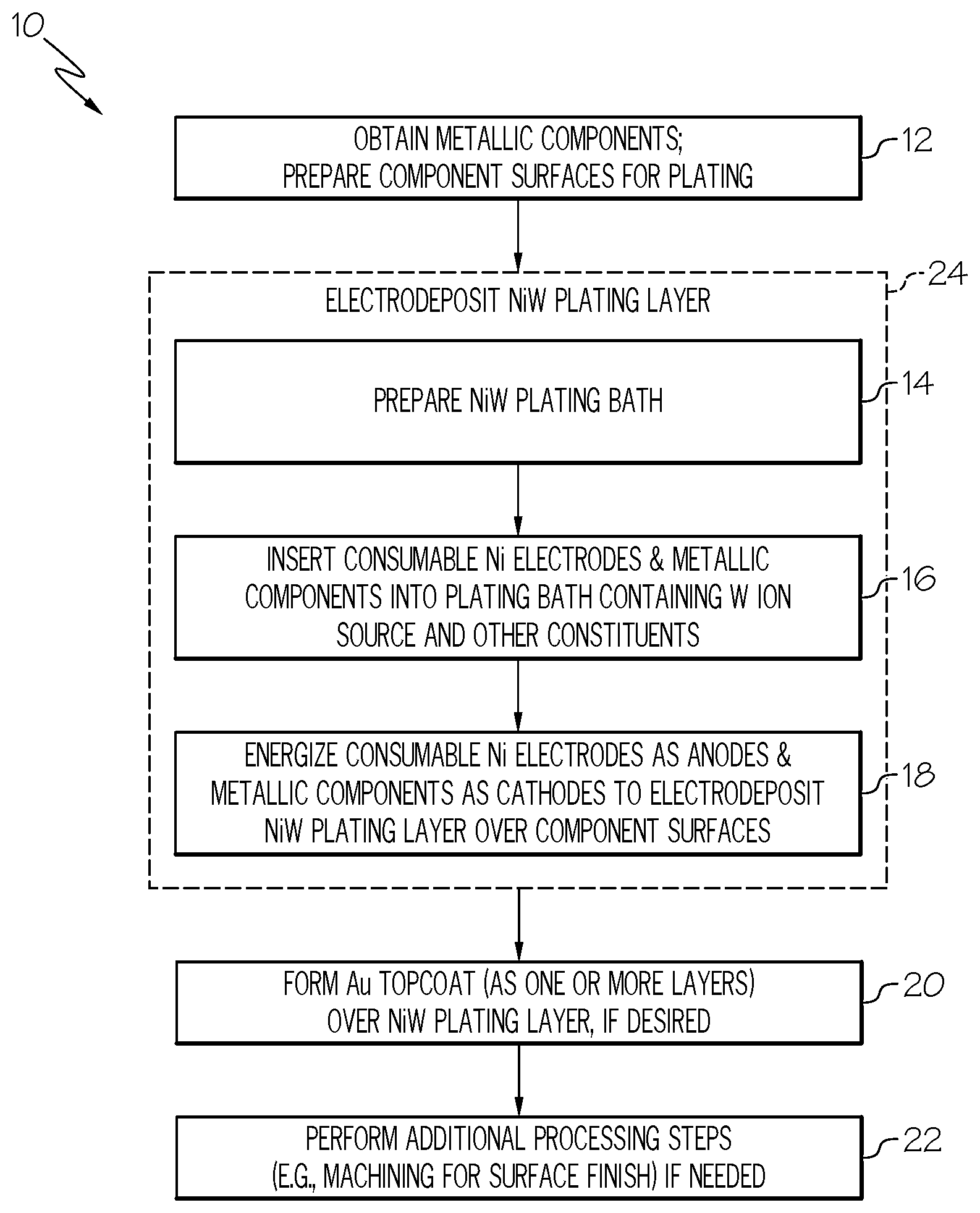
[0016] FIG. 1 is a flowchart of a method for producing a coating including or consisting of a NiW plating layer formed over selected surfaces of a metallic component, such as the terminals of an electrical connector or the sliding surfaces of a high temperature (e.g., engine) component, as illustrated in accordance with an exemplary embodiment of the present disclosure;
[0017] FIG. 2 is a schematic of an exemplary NiW plating apparatus, which can be utilized to electrodeposit an NiW plating layer over selected surfaces of a metallic component, when carrying-out the method of FIG. 1;
[0018] FIG. 3 is a simplified cross-sectional view of a limited region of an exemplary coating containing an NiW plating layer and an Au topcoat, which are formed over an underlying metallic component and which can be produced pursuant to the method of FIG. 1 in an exemplary embodiment; and
[0019] FIG. 4 is an isometric view of a female electrical connector and the pins of a mating male electrical connector (the remainder of which is not shown for clarity), both of which contain terminals over which the disclosed coatings are usefully formed.
[0020] For simplicity and clarity of illustration, descriptions and details of well-known features and techniques may be omitted to avoid unnecessarily obscuring the exemplary and non-limiting embodiments of the invention described in the subsequent Detailed Description. It should further be understood that features or elements appearing in the accompanying figures are not necessarily drawn to scale unless otherwise stated.
DETAILED DESCRIPTION
[0021] The following Detailed Description is merely exemplary in nature and is not intended to limit the invention or the application and uses of the invention. The term "exemplary," as appearing throughout this document, is synonymous with the term "example" and is utilized repeatedly below to emphasize that the description appearing in the following section merely provides multiple non-limiting examples of the invention and should not be construed to restrict the scope of the invention, as set-out in the Claims, in any respect. As further appearing herein, statements indicating that a first layer is "formed over," "formed on," "deposited over," or "deposited on" a second layer, surface, or body do not require that that the first layer is directly bonded to and intimately contacts the second layer, surface, or body unless otherwise expressly stated by, for example, stating the first layer is "formed directly on," "deposited directly on," "is formed in contact with," or "contacts" the second layer, surface, or body.
Definitions
[0022] The following definitions apply throughout this document. Those terms not expressly defined here or elsewhere in this document are assigned their ordinary meaning in the relevant technical field.
[0023] Coating--One or more layers of material formed over a component surface. This term encompasses the more specific term "coating system" defined below.
[0024] Coating System--A coating structure containing at least two material layers having varying compositions, such as one or more Au layers joined to a component body by an intervening NiW plating layer.
[0025] Component--Any article of manufacture over which a coating can be formed. This term is synonymous with or encompasses similar terms including "substrate," "part," and "workpiece."
[0026] Electrical Connector--Any component or structure utilized to provide an a current- or signal-carrying electrical connection between two points or nodes including wirebonds and mating connector devices, such as male (e.g., pin), female (e.g., socket), and hybrid (e.g., pin and socket) connectors.
[0027] Gold (Au) Topcoat--One or more layers predominately composed of Au by weight and formed over an NiW plating layer.
[0028] Nickel (Ni) Barrier Layer--A layer composed essentially of pure Ni by weight and deterring unfavorable chemical reactions with an underlying material layer, component, or body of material.
[0029] Nickel-tungsten (NiW) plating layer--A layer composed predominately of Ni and W by weight and deterring unfavorable chemical reactions with an underlying material layer, component, or body of material.
[0030] Ni Pellets--Discrete bodies or pieces of material, such as shot, predominately composed of Ni by weight, regardless of shape or size.
Overview
[0031] As discussed briefly in the foregoing BACKGROUND, pure Ni plating layers are beneficially electrodeposited on selected surfaces of metallic components to improve wear properties and to prevent undesired chemical degradation, such as corrosion, of the underlying component or substrate. As a more specific example, pure Ni plating layers are usefully formed on contact surfaces of high performance electrical connectors over which Au topcoats are further deposited to lower contact resistance. In other instances, pure Ni plating layers may be formed over sliding surfaces, particularly over the sliding surfaces of high temperature components, to provide enhanced wear resistance. However, as further discussed above, pure Ni plating layers remain limited in certain respects and, in many instances, provide only modest improvements in the wear and corrosion properties of the coating system. Additionally, the plating processes utilized to electrodeposit pure Ni plating layers are often hampered by various constraints, such as bath instabilities, poor bath life longevity, relatively sluggish deposition rates, and correspondingly high process and material costs.
[0032] Relative to pure Ni plating layers, NiW plating layers can potentially provide greater enhancement to the wear and corrosion resistance properties of a coating or coating system. The plating processes utilized to electrodeposit NiW plating layers are, however, considerably more complex than those utilized to electrodeposit pure Ni. This is due, at least in part, to difficulties encountered when attempting to deposit a (typically binary) alloy having a specific fractional composition of W to Ni. Further, NiW electrodeposition processes are also typically prone to the accumulation of plating bath impurities, which can result in rough deposits leading to microcrack formation and propagation. Once formed, microcracks can detract from the intended functionality of the NiW plating layer to serve a physical shield against undesired chemical reactions with the underlying component, in applications in which the NiW plating layer is utilized as a barrier layer. Specifically, such microcracks can lead to greater diffusion of outer material layers (e.g., an Au topcoat), if present, into the parent material of the underlying component or substrate. Still other challenges are also encountered when electrodepositing NiW plating layers. For example, if Ni ions are supplied to the plating bath in the form of a Ni-containing sulfate chemical additive, the gradual build-up of sulfates can occur over time thereby greatly reducing bath life and raising the cost of the NiW electrodeposition process. Similarly, if not deposited onto the plated component at a sufficiently controlled rate, an abundance of Ni ions can develop within the plating bath. Eventually, the plating bath may saturate with Ni ions, which may necessitate partial dumping of the plating bath and refilling with plating bath solution lacking Ni. This again prolongs, complicates, and adds cost to the NiW electrodeposition process.
[0033] To overcome many, if not all of the aforementioned challenges, the following provides improved processes for forming coatings and coatings systems containing NiW plating layers. Embodiments of the below-described NiW electrodeposition process reduce or eliminate the accumulation of sulfates and other undesired chemical species within the plating bath to significantly extend bath life and lower material costs. This is accomplished, in part, through the incorporation of consumable or dissolvable Ni electrodes into the NiW electrodeposition process, rather than utilizing inert (e.g., platinum-coated titanium) anodes as conventionally practiced in the context of pure Ni plating processes. Embodiments of the plating bath solution further contain at least one chemical serving as an anode corrosion accelerant, such as chloride, which promotes the controlled dissolution of the consumable Ni electrodes into the plating bath. The anode corrosion accelerant is maintained in the plating bath in a carefully controlled amount or fraction, which is sufficient to prevent scale build-up over the surfaces of the Ni electrodes, while further limiting dissolution of the Ni electrodes to a rate substantially equivalent to the rate of N ion deposition onto the component surfaces subject to plating.
[0034] In various embodiments, the controlled amount of anode corrosion accelerant added to and generally maintained within the NiW plating bath may be determined utilizing different approaches. In one approach, the amount of anode corrosion accelerant is determined based upon a target W content of the NiW plating layer, as well as an estimated cumulative surface area of the Ni electrodes submerged in the plating bath and energized as anodes during the NiW electrodeposition process. As the electrodeposition process progresses and the Ni electrodes dwindle in size, new or fresh Ni electrodes may be repeatedly introduced into the plating bath to maintain the cumulative surface area of Ni electrodes and plated surface area of the metallic component surface within a predetermined range or desired relationship. This may be accomplished by, for example, providing the Ni electrodes as consumable Ni pellets or shot, which are retained within an inert mesh basket or other container and which are replenished periodically during the NiW electrodeposition process.
[0035] Through the usage of consumable Ni electrodes and tailored amounts of at least one anode corrosion accelerant, the gradual accumulation of undesired chemical species, such as sulfates, within the plating bath can be reduced or eliminated. Bath life is prolonged as a result, potentially to near infinite lifespans. Further, as compared to inert anodes, the consumable Ni electrodes utilized in the NiW electroplating process can be energized at reduced voltages, utilizing either a Direct Current (DC) or Alternating Current (AC) power source, to minimize oxygen evolution and carbonate production during the electroplating process. This, again, extends useful bath life and reduces processing costs. Finally, as a yet further benefit, embodiments of the below-described plating process can boost mas transfer within the plating bath diffusion zone to achieve deposition rates well-exceeding those attained by conventional Ni plating processes. Process efficiency is thus improved, while costs are reduced. These and other benefits may be further enhanced by formulating the plating bath to contain tailored amounts of additional constituents serving as chelating or structuring agents, such as ammonium hydroxide (NH.sub.4OH) and/or other organic acids; and controlling other plating process parameters during the plating process, as further discussed below. Exemplary embodiments of a coating formation method including the electrodeposition of NiW plating layers will now be described in conjunction with FIG. 1.
[0036] Examples of Methods for Forming Coatings and Coating Systems Including Niw Plating Layers
[0037] FIG. 1 is a flowchart of an exemplary coating formation method 10 for forming a coating or coating system including NiW plating layers over metallic components, such as the terminals of high performance electrical connectors or the sliding surfaces of a high temperature (e.g., engine) component, as illustrated in accordance with an exemplary embodiment of the present disclosure. As a point of emphasis, a given coating or coating system may contain and, perhaps, may consist of a single NiW plating layer, which may be deposited over a metallic component. In certain applications, the NiW plating layer is beneficially deposited over the sliding surface of a metallic component, typically (although non-essentially) a metallic component utilized in a high temperature operating environment, such as a valve part or other component contained in an internal combustion or gas turbine engine. In other applications, the NiW plating layer may be combined with additional material layers to yield a multi-layer coating system. For example, and as further discussed below in conjunction with FIG. 3, one or more Au topcoat layers may be formed over the NiW plating layer when the plated component is the terminal of an electrical connector. Various other coatings and coating systems can be formed pursuant to method 10, as appropriately modified to suit a particular application or usage, providing that the coating or coating system consists of or includes at least one NiW plating layer as described below.
[0038] In the example of FIG. 1, coating formation method 10 includes a number of process steps identified as STEPS 12, 14, 16, 18, 20, 22, with STEPS 14, 16, 18 performed pursuant to an overarching NiW plating sub-process identified as "PROCESS BLOCK 24." Depending upon the particular manner in which coating formation method 10 is implemented, each illustrated process step (STEPS 12, 14, 16, 18, 20, 22) may entail a single process or multiple sub-processes. Further, the steps shown in FIG. 1 and described below are offered by way of non-limiting example only. In alternative embodiments of method 10, additional process steps may be performed, certain steps may be omitted, and/or the illustrated steps may be performed in varying sequences. For example, in further implementations, STEP 20 of method 10 may be omitted or modified such that the NiW plating layer is left as a standalone protection solution (e.g., as wear protection for sliding surfaces) or, instead, overlaid by one or more additional material layers other than an Au topcoat in the completed coating system.
[0039] For ease of description, coating formation method 10 is principally described below as carried-out to form a coating or multi-layer coating system over selected surfaces of a single metallic component. This notwithstanding, it will be appreciated that any practical number of metallic components may be processed in parallel to form coatings or coating systems over selected surfaces of a plurality of components in accordance with the below-described process steps. For example, in the case of smaller (e.g., stamped) metallic components, such as the terminals of an electrical connector, a reel-to-reel plating process can be utilized to from coatings or coating systems a connected series of parts or components, such as stamped pins or sockets, which are passed through the below-described NiW plating bath and other processing stages for large scale production.
[0040] With continued reference to FIG. 1, coating formation method 10 commences at STEP 12 during which the metallic component or components to be coated are obtained; e.g., by purchase from a third party supplier or by independent fabrication. The surfaces of the metallic component or components targeted for electrodeposition of the NiW plating layer are further prepared during STEP 12. In embodiments, surface preparation may involve degreasing or otherwise cleaning the targeted component surfaces. For example, if desired, surface oxides may be removed from the component surfaces utilizing a sulfuric acid dip or similar process. Grinding, polishing, lapping, and/or other such mechanical operations can further be performed, as appropriate, to improve surface finish prior to NiW plating layer electrodeposition. Finally, any component surfaces not desirably coated with the NiW plating layer may be masked during STEP 12.
[0041] Coating formation method 10 next advances to PROCESS BLOCK 24. During PROCESS BLOCK 24, at least one NiW plating layer is electrodeposited over the targeted component surfaces. As indicated at STEP 14, the NiW electrodeposition process involves formulating or preparing the plating bath solution to possess a chemistry suitable for electrodeposition of the NiW plating layer having a desired composition and other characteristics, such as a desired morphology. Generally, the formulation of the NiW plating bath will depend, at least in part, on the target W content of the NiW plating layer. As the W content of the NiW plating layer will vary among embodiments, so too will the composition of the NiW plating bath. However, by way of example, the target W content of the NiW plating layer may range from about 15% and 45% by weight, preferably from about 25% to about 35% by weight, and more preferably may be substantially equivalent to 30% by weight. In other embodiments, the W content of the NiW plating layer may be greater than or lesser than the aforementioned ranges.
[0042] In accordance with embodiments of the present disclosure, the NiW plating bath is formulated such that an amount of anode corrosion accelerant in the plating bath is controlled to balance the amount of Ni dissolution at the anode (the energized consumable Ni electrodes) to the amount of Ni deposition at cathode (the plated part), combined with any additional Ni ion source within the plating bath, to achieve a desired composition of the NiW layer. In many embodiments, the plating bath will not contain any additional Ni ion source such that anode corrosion accelerant concentration is tailored to achieve Ni dissolution at the anode relative to the Ni deposition at cathode to arrive at the desired composition of the NiW layer. However, in other embodiments, the Ni dissolution at the anode may be purposefully undershot with additional Ni ions introduced in the form of a chemical additive, such as Ni sulfate, to allow greater flexibility in adjusting chemistry during the electrodeposition process. In such embodiments, bath life may still be extended as a relatively small or reduced amount of the Ni sulfate (or other Ni-containing chemical) may be added to the plating bath.
[0043] In embodiments, the anode corrosion accelerant can include or assume the form of chloride. The chloride can be added as a chloride-containing agent or chemical, such as nickel chloride (NiCl.sub.2), ammonia chloride (NH.sub.4Cl), or sodium chloride (NaCl). Ideally, the amount of anode corrosion accelerant is carefully tailored in relation to the other constituents of the NiW plating bath and to prevent scale build-up over the surfaces of the Ni electrodes, while further limiting dissolution of the Ni electrodes to a rate substantially equivalent to the rate of N ion deposition onto the component surfaces subject to plating. The amount of anode corrosion accelerant added to the plating bath may be determined based, at least in part, on the target W content of the NiW plating layer and a cumulative surface area of the consumable Ni electrodes. As a result, the amount of anode corrosion accelerant added to and generally maintained within the NiW plating bath will vary amongst different implementations of method 10. This notwithstanding, and by way of non-limiting example only, the chloride range in the plating bath ranges between about 0.0002 and about 0.01 moles per liter (mol/liter); and, more preferably, between 0.0008 and 0.0025 mol/liter. The foregoing exemplary molarity ranges apply when chloride is selected as the anode corrosion accelerant or as at least one of the anode corrosion accelerants, if multiple accelerant types are utilized. In other implementations, a different type of anode corrosion accelerant may be utilized or chloride may be employed as the anode corrosion accelerant, but in a concentration greater than or less than the aforementioned ranges.
[0044] The controlled amount of anode corrosion accelerant introduced into and maintained in the NiW plating above may thus be defined, in part, based upon the desired Ni ion concentration in the bath. Other process parameters (e.g., voltages, temperatures, agitation intensities, etc.) and whether a supplemental Ni ion source (e.g., a Ni-containing chemical additive) is present within the bath will also impact the N ion concentration within the bath. As with the various other constituents of the NiW plating bath, the Ni ion concentration will vary among different implementations of method 10. However, by way of example, the Ni ion concentration within the NiW plating bath may be maintained through the NiW electrodeposition process in a range between about 5 grams and about 18 grams Ni per liter of plating bath solution; or, stated differently, between about 0.085 to about 0.307 mol/liter. In a more specific example, the Ni ion concentration within the NiW plating bath may be maintained in a range between about 11 and about 13.5 grams per liter; or between about 0.187 to about 0.230 mol/liter.
[0045] In addition to the anode corrosion accelerant, the NiW plating bath also contains at least one W ion source. The W ion source is conveniently provided as a water-soluble additive containing W, such as sodium tungstate dihydrate (Na.sub.2WO.sub.4.2H.sub.2O). Additionally, the plating bath will further contain a liquid carrier, such as an aqueous or alcohol-based solvent. The plating bath chemistry may also be formulated to include other ingredients or constituents including chelating agents and pH balancing agents; e.g., in one embodiment, a complex of an organic acid, such as citric acid (C.sub.6H.sub.8O.sub.7) and ammonia (NH.sub.3) may be provided within the bath (e.g., added in solution as NH.sub.4OH) to serve as a chelating or structuring agent. With respect to the NH.sub.3 additive, in particular, this additive may contribute ammonium hydroxide (OH--) ions when reacted in the plating bath, which are highly effectively in service as chelating agents. In one embodiment, adequate NH.sub.3 (or another OH-- donor) is introduced into the plating bath to provide ammonium hydroxide (OH--) ions in the range of about 1.0 to about 2.0 mol/liter; and, more preferably, in the range of 1.3 to 1.7 mol/litter. Finally, as noted above, the NiW plating bath will also contain a Ni ion source in the form of the consumable NiW electrodes; although the possibility that the NiW plating bath can be formulated to contain another Ni ion source, such as a Ni sulfate or other chemical species, in addition to the Ni ion electrodes is not precluded. Various other bath formulations are also possible.
[0046] At STEP 16, the consumable Ni electrodes and metallic components are inserted into the NiW plating bath, whether by inserting the Ni electrodes and the metallic component into the plating bath or by first positioning the at least one electrode and the component in a vessel and subsequently filling the vessel with plating bath solution. The Ni electrodes are then energized as anodes and the metallic components are energized as cathodes to carry-out the NiW electrodeposition process and thereby deposit the NiW plating layer over the selected component surfaces. The consumable Ni electrodes can generally be energized at reduced voltages, whether utilizing a Direct Current (DC) or Alternating Current (A/C) power source, to minimize oxygen evolution and carbonate production within the plating bath. Advantageously, the usage of soluble Ni anodes generally enables reduced anode voltages to lower decomposition products and thereby prolong bath life. In one embodiment, the at least one consumable Ni electrode and the metallic component are energized at a current density (e.g., a direct current density) between 1 and 5 ampere per decimeter squared.
[0047] Various parameters are controlled during the NiW electrodeposition process. Bath agitation may be applied and, in embodiments, may range from about 100 to about 1000 revolutions per minute (RPM). The temperature and pH level of the plating bath may also be monitored and controlled. In one implementation, bath chemistry is formulated to maintain NiW plating bath at a pH between about 5 and about 9 and, more preferably, a pH of about 7.+-.1 through the electroplating process. In other instances, the pH level of the plating bath may be greater or less than the aforementioned range. As the plating process progress and the Ni electrodes dwindle in size, new or fresh Ni electrodes may be repeatedly introduced into the plating bath to maintain the cumulative surface area of Ni electrodes and plated surface area of the metallic component surface within a predetermined range or desired relationship. This may be accomplished by, for example, providing the Ni electrodes as consumable Ni pellets or shot, which are retained within an inert mesh basket or other container and which are replenished periodically during the NiW electrodeposition process, as further described below in conjunction with FIG. 2.
[0048] FIG. 2 is a schematic of an exemplary NiW plating apparatus 26, which can be utilized to electrodeposit an NiW plating layer 30 over surfaces of a metallic component 32 during PROCESS BLOCK 24 of coating formation method 10 (FIG. 1). As schematically depicted in FIG. 2, plating apparatus 26 includes a vessel 34 retaining a plating bath solution 36. Metallic component 32 is electrically connected, either directly or indirectly (e.g., through an intervening bracket or fixture) to a negative terminal of power source 38 by a first electrical connection 40. The positive terminal of power source 38 is further connected, either directly or indirectly, to one or more consumable Ni electrodes by a second electrical connection 42. In the illustrated example, specifically, power source 38 is electrically coupled to a mesh basket 44 composed of an inert electrically-conductive material, such as titanium. Ni shot 46 is held within mesh basket 44 and is energize when with the application of a controlled voltage across mesh basket 44 and metallic component 32. As Ni shot 46 dissolves during the plating process, new or fresh Ni shot 46 may be added to mesh basket 44, as indicated in FIG. 2 by arrow 48. Certain variations in the cumulative surface area of consumable Ni shot 46 (the anodes) will occur, with the surface area-to-volume ratio increasing as the pieces of shot decrease in size. However, by repeatedly adding fresh consumable Ni pellets 46 to NiW plating bath 36 as the electroplating process progresses, a ratio between a cumulative surface area of the consumable Ni pellets and a surface area of the component surface can be maintained within a predetermined range. In embodiments, Ni pellets 46 may be added and process parameters controlled to maintain a Ni ion concentration within the above-described molarity ranges (between about 0.085 to about 0.307 mol/liter; and, perhaps, between about 0.187 to about 0.230 mol/liter) throughout a majority and, perhaps, the substantial entirety of the electroplating process.
[0049] Returning once again to FIG. 1, coating formation method 10 next progresses to STEP 20 (if performed) during which an Au topcoat is formed over the newly-deposited NiW plating layer. When formed, the Au topcoat will often have a thickness less than the thickness of the NiW plating layer; e.g., in embodiments, the Au topcoat may have a thickness ranging from 0.381 micron (.mu.m) to 1.016 .mu.m, while the NiW plating layer will often have a thickness ranging between 1.27 .mu.m and 5.08 .mu.m. In this regard, and as noted above, the provision of a microcrystalline, essentially microcrack-free NiW plating layer may allow the thickness the Au topcoat to be appreciably reduced for cost savings. In other high performance applications, the thickness of the Au topcoat may approach or potentially exceed that of the NiW plating layer. For example, when the coating is formed over the terminals of an electrical connector deployed onboard a spacecraft or aircraft, the Au topcoat may range between 2.54 .mu.m and 5.08 .mu.m, with the NiW plating layer having a thickness as specified above. In still further implementations, the NiW plating layer and/or the Au topcoat may be thickener or thinner than the aforementioned ranges; or STEP 20 of method 10 may be omitted. The provision of such an essentially microcrack-free NiW plating layer may also serve as an effective barrier layer for preventing undesired diffusion of Au topcoat (or other overlying material layer) into the substrate in at least some realizations of method 10.
[0050] Finally, at STEP 22 of coating formation method 10 (FIG. 1), zero or more additional processing steps are performed to complete fabrication of the coating or coating system. This may include machining (e.g., lapping, polishing, and/or grinding) of the newly-deposited Au topcoat to achieve a desired surface finish and/or dimensional tolerance. Heat treatment can also be performed for densification or other purposes. Coating formation method 10 then concludes and can be repeated, as needed, an iterative basis to further form similar or identical coatings or coating systems over other metallic components. In other implementations of method 10, and as previously indicated, STEPS 20, 22 may not be performed such that the NiW plating layer electrodeposited during PROCESS BLOCK 24 serves as a standalone protection solution; e.g., as may be useful when the NiW plating layer is deposited onto a sliding surface or other contact surface for enhanced wear resistance. Alternatively, other coating layer or coating systems may be formed over the NiW plating layer in still further embodiments, such as a environmental barrier coating and/or thermal barrier coating.
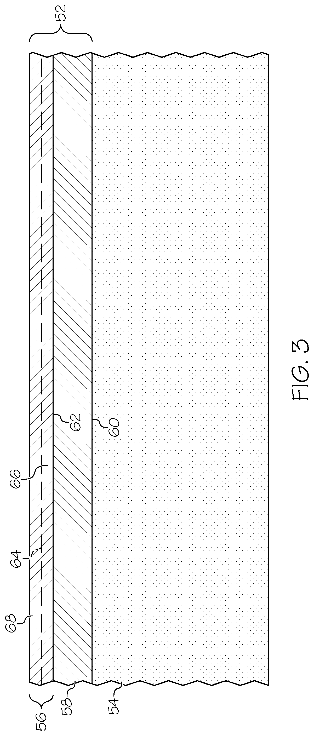
[0051] FIG. 3 is a simplified cross-sectional view of a limited region of a coating system 52, which is formed over an underlying metallic component 54 and which may be produced pursuant to coating formation method 10 in accordance with an exemplary embodiment of the present disclosure. In this example, coating system 52 includes an Au topcoat 56 and an electrodeposited NiW plating layer 58, which is formed between Au topcoat 56 and metallic component 54. Specifically, NiW plating layer 58 is formed over and in contact with component surface 60 of metallic component 54. Au topcoat 56 is, in turn, formed over and in contact with outer surface 62 of NiW plating layer 58. As indicated in FIG. 3 by dashed line 64, Au topcoat 56 can be formed as two (or more) layers. In various implementations, Au topcoat 56 is formed to include a first or base Au layer 66, which is plated directly onto NiW plating layer 58; and a second or outer Au layer 68, which is plated directly onto base Au layer 66. Such an arrangement may be beneficial when Au topcoat 56 is desirably formed to have a relatively high thickness and is utilized within a high performance application, such as a spaceborne or an airborne connector. In such embodiments, base Au layer 66 may be formed as relatively thin strike plating layer (e.g., a layer having a thickness equal to or less than 1 .mu.m) to enhance adhesion between NiW plating layer 58 and the thicker outer Au layer 68. Wear testing has shown that coating systems similar or identical to coating system 52 perform comparably and, in certain cases, outperform conventional coating systems containing pure Ni plating layers in useful life cycle limits.
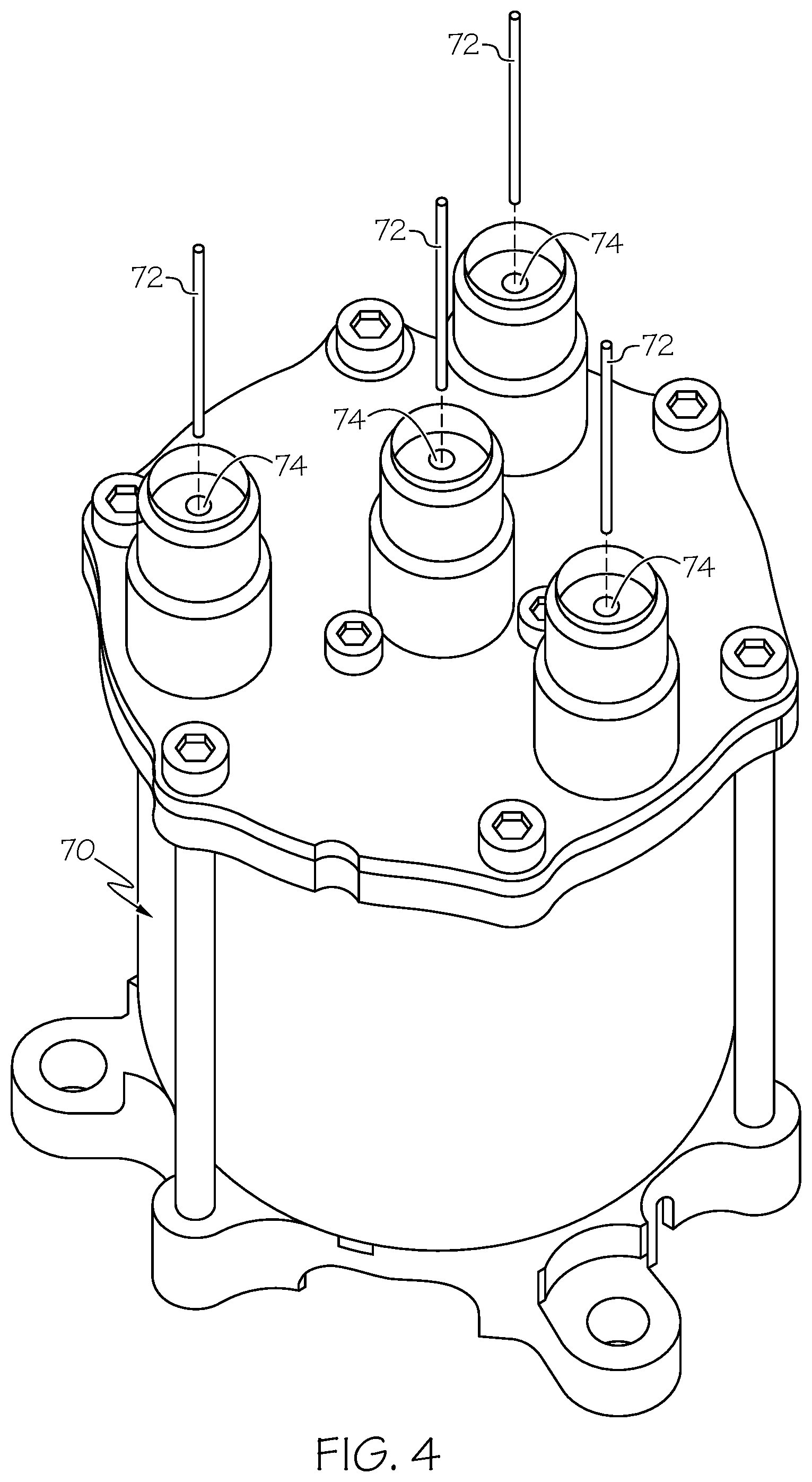
[0052] Turning lastly to FIG. 4, there is shown an isometric view of a female electrical connector 70 and a number of pins 72, which may be included in a non-illustrated mating male electrical connector. Pins 72 engage into sockets 74 when the non-illustrated male electrical connector is plugged into female electrical connector 70. To decrease contact resistance across the electrical interface formed between each pin 72 and its mating socket 74, the above-described coatings or coating systems (e.g., coating system 52 shown in FIG. 3) may be formed over the outer contact surfaces of pins 72 and/or over the inner contact surfaces of sockets 70. In this particular example, female electrical connector 70 is of the type deployed onboard spacecraft and aircraft and, thus, a coating having a relatively thick Au topcoat may be formed over the interior of sockets 74 and over pins 72 of the mating male electrical connector. The provision of the NiW plating layer, as previously noted, may further enhance the wear and corrosion resistance properties of sockets 74 and pins 72, as may be desired in such applications to satisfy stringent mission requirements in certain instances. The example of FIG. 4 notwithstanding, it is again emphasized that the coatings or coating systems described herein can be formed over any type of metallic article or component, without limitation.
CONCLUSION
[0053] There has thus been provided describes processes for depositing NiW plating layers in an essentially crack-free, nanocrystalline state. Additionally, embodiments of the plating process minimize, if not eliminate the accumulation of sulfates and undesired chemical species within the plating bath to greatly extend bath life. By virtue of its nanocrystalline microcrack-free morphology, the NiW plating layer provides excellent shielding of undesired chemical reactions between the Au topcoat (when present) and the underlying substrate material or component body, as is beneficial when the NiW plating layer is utilized as a barrier layer. This, in turn, may allow the thickness of the Au topcoat to be reduced for cost savings, while maintaining coating system performance at desired levels in embodiments in which the NiW plating layer is included in a coating system further containing such an Au topcoat. Alternatively, in such embodiments, the NiW plating layer may be utilized to enhance coating system performance, while leaving the thickness of the Au topcoat unchanged. This latter approach may be preferable in high performance application, as in the case of electrical connectors deployed onboard aircraft or spacecraft. Generally, the NiW plating layer may help improve oxidation, corrosion, and/or wear resistance of the plated part in certain instances. This material system is beneficially utilized to coat current-carrying electronic structures, such as electrical terminals or connectors. Examples of current-carrying electronic structures include wirebonds, as well as larger mating interconnect structures or devices, such as male (e.g., pin) and female (e.g., socket) connectors. In yet other embodiments, the NiW plating layer may be utilized in isolation or, perhaps, with other types of material layers to provide other performance enhancements, such as increasing sliding surface wear resistance.
[0054] Terms such as "comprise," "include," "have," and variations thereof are utilized herein to denote non-exclusive inclusions. Such terms may thus be utilized in describing processes, articles, apparatuses, and the like that include one or more named steps or elements, but may further include additional unnamed steps or elements. While at least one exemplary embodiment has been presented in the foregoing Detailed Description, it should be appreciated that a vast number of variations exist. It should also be appreciated that the exemplary embodiment or exemplary embodiments are only examples, and are not intended to limit the scope, applicability, or configuration of the invention in any way. Rather, the foregoing Detailed Description will provide those skilled in the art with a convenient road map for implementing an exemplary embodiment of the invention. Various changes may be made in the function and arrangement of elements described in an exemplary embodiment without departing from the scope of the invention as set-forth in the appended Claims.
* * * * *
D00000
D00001
D00002
D00003
D00004
XML
uspto.report is an independent third-party trademark research tool that is not affiliated, endorsed, or sponsored by the United States Patent and Trademark Office (USPTO) or any other governmental organization. The information provided by uspto.report is based on publicly available data at the time of writing and is intended for informational purposes only.
While we strive to provide accurate and up-to-date information, we do not guarantee the accuracy, completeness, reliability, or suitability of the information displayed on this site. The use of this site is at your own risk. Any reliance you place on such information is therefore strictly at your own risk.
All official trademark data, including owner information, should be verified by visiting the official USPTO website at www.uspto.gov. This site is not intended to replace professional legal advice and should not be used as a substitute for consulting with a legal professional who is knowledgeable about trademark law.