Wrapper for Tobacco Industry Products
HOLFORD; Steven
U.S. patent application number 16/480031 was filed with the patent office on 2019-12-05 for wrapper for tobacco industry products. The applicant listed for this patent is British American Tobacco (Investments) Limited. Invention is credited to Steven HOLFORD.
| Application Number | 20190367235 16/480031 |
| Document ID | / |
| Family ID | 58463046 |
| Filed Date | 2019-12-05 |


View All Diagrams
| United States Patent Application | 20190367235 |
| Kind Code | A1 |
| HOLFORD; Steven | December 5, 2019 |
Wrapper for Tobacco Industry Products
Abstract
A wrapper for a group of tobacco industry products including a barrier material, and a cut-line in the barrier material to form a tab arranged to be pulled so that a tear propagates from an end of the cut-line to form an extraction opening in the barrier material, where the barrier material includes a weakened region having a width greater than the width of said cut-line and which extends in a direction across the end of said cut-line to control the direction of the tear propagating from the end of said cut-line.
| Inventors: | HOLFORD; Steven; (London, GB) | ||||||||||
| Applicant: |
|
||||||||||
|---|---|---|---|---|---|---|---|---|---|---|---|
| Family ID: | 58463046 | ||||||||||
| Appl. No.: | 16/480031 | ||||||||||
| Filed: | January 18, 2018 | ||||||||||
| PCT Filed: | January 18, 2018 | ||||||||||
| PCT NO: | PCT/GB2018/050139 | ||||||||||
| 371 Date: | July 23, 2019 |
| Current U.S. Class: | 1/1 |
| Current CPC Class: | B65D 77/003 20130101; B65D 77/02 20130101; B65D 85/1045 20130101; B65D 75/5838 20130101 |
| International Class: | B65D 77/02 20060101 B65D077/02; B65D 85/10 20060101 B65D085/10; B65D 75/58 20060101 B65D075/58 |
Foreign Application Data
| Date | Code | Application Number |
|---|---|---|
| Jan 23, 2017 | GB | 1701096.8 |
Claims
1. A wrapper for a group of tobacco industry products comprising: a barrier material; a cut-line in the barrier material to form a tab arranged to be pulled so that a tear propagates from an end of the cut-line to form an extraction opening in the barrier material; wherein the barrier material includes a weakened region having a width greater than the width of said cut-line and which extends in a direction across the end of said cut-line to control the direction of the tear propagating from the end of said cut-line.
2. A wrapper according to claim 1, wherein said weakened region is configured to guide a tear propagating from the end of the cut-line.
3. A wrapper according to claim 1, wherein the barrier material comprises a major surface and an end surface separated from the major surface by a fold-line, wherein the cut-line is formed in said major surface so that when the tab is pulled, the tear propagates in the major surface from the end of the cut-line towards said fold-line between said major surface and said end surface.
4. A wrapper according to claim 3, wherein the weakened region extends into the end surface from the major surface over the fold-line.
5. A wrapper according to claim 3, wherein the weakened region comprises a plurality of parallel lines of weakness in the barrier material that extend in a direction away from the end of said cut-line towards the end surface, said lines of weakness being parallel to a direct tear propagation path, the direct tear propagation path being defined as the shortest path that extends from the end of the cut-line to the end surface.
6. A wrapper according to claim 5, wherein the cut-line extends between the lines of weakness.
7. A wrapper according to claim 5, wherein the lines of weakness are spaced from the end of the cut-line in the direction of the direct tear propagation path.
8. A wrapper according to claim 5, wherein one of said parallel lines of weakness extends along said direct tear propagation path.
9. A wrapper according to claim 3, wherein the weakened region is configured to redirect a tear propagating from the end of the cut-line towards a direct tear propagation path, the direct tear propagation path being defined as the shortest path that extends from the end of the cut-line to the fold-line between the major surface and the end surface.
10. A wrapper according to claim 9, wherein the weakened region comprises a first and a second converging line of weakness, said first and second converging lines of weakness meeting on said direct tear propagation path.
11. A wrapper according to claim 10, wherein the end of the cut-line extends between said first and second converging lines of weakness.
12. A wrapper according to claim 10, wherein a third line of weakness extends along said direct tear propagation path from where said first and second lines of weakness meet.
13. A wrapper according to any of claim 5, wherein the lines of weakness are score lines extending partially through the thickness of the barrier material.
14. A wrapper according to claim 13, wherein the lines of weakness are laser cut score lines.
15. A wrapper according to claim 1, wherein the cut-line extends fully through the thickness of the barrier material.
16. A wrapper according to claim 3, comprising a cover flap on the barrier material that extends over the cut-line, said cover flap being adhered to the barrier material such that lifting the cover flap pulls the tab to propagate the tear from the end of the cut-line.
17. A wrapper according to claim 16, wherein at least a peripheral region of the cover flap extending beyond the cut-line is adhered to the barrier material by a pressure sensitive releasable adhesive.
18. A wrapper according to claim 16, wherein the cover flap is adhered to an outer face of the barrier material and said weakened region is formed on said outer face.
19. A wrapper according to claim 16, wherein the cover flap is adhered to an outer face of the barrier material and said weakened region is formed on an inner face.
20. A bundle comprising the wrapper of claim 1, wrapped around a group of tobacco industry products.
21. A tobacco industry product pack comprising the bundle of claim 20 and a container having a base, and a lid hingedly attached to the base, the bundle being received in the base.
Description
TECHNICAL FIELD
[0001] The present invention relates to a wrapper for a group of tobacco industry products, particularly but not exclusively to a wrapper for packaging smoking articles such as cigarettes. The invention also relates to a bundle comprising the wrapper according to the invention and to a tobacco industry product pack comprising the bundle.
BACKGROUND
[0002] Cigarette packs are known to have a re-closable label provided on a wrapped bundle of cigarettes. Pulling the label exposes an extraction opening for extracting the cigarettes from the bundle. The label includes a region of pressure sensitive adhesive that allows the label to be re-positioned to close the extraction opening after first opening.
SUMMARY
[0003] In accordance with embodiments of the invention, there is provided a wrapper for a group of tobacco industry products comprising: [0004] a barrier material; [0005] a cut-line in the barrier material to form a tab arranged to be pulled so that a tear propagates from an end of the cut-line to form an extraction opening in the barrier material; [0006] wherein the barrier material includes a weakened region having a width greater than the width of said cut-line and which extends in a direction across the end of said cut-line to control a direction of the tear propagating from the end of said cut-line.
[0007] The weakened region is preferably configured to guide a tear propagating from the end of the cut-line.
[0008] The barrier material may comprise a major surface and an end surface separated from the major surface by a fold-line. The cut-line may be formed in said major surface so that when the tab is pulled, the tear propagates in the major surface from the end of the cut-line towards said fold-line between said major surface and said end surface.
[0009] Preferably, the weakened region extends into the end surface from the major surface over the fold-line.
[0010] The weakened region may comprise a plurality of parallel lines of weakness in the barrier material that extend in a direction away from the end of said cut-line towards the end surface, said lines of weakness being parallel to a direct tear propagation path, the direct tear propagation path being defined as the shortest path that extends from the end of the cut-line to the end surface.
[0011] The cut-line may extend between the lines of weakness.
[0012] In another embodiment, the lines of weakness may be spaced from the end of the cut-line in the direction of the direct tear propagation path.
[0013] In any embodiment employing parallel lines of weakness, one of said parallel lines of weakness may extend along said direct tear propagation path.
[0014] In another embodiment, the weakened region is configured to redirect a tear propagating from the end of the cut-line towards the direct tear propagation path.
[0015] In this embodiment, the weakened region may comprise a first and a second converging line of weakness, said first and second converging lines of weakness meeting on said direct tear propagation path.
[0016] In some embodiments, the end of the cut-line extends between said first and second converging lines of weakness.
[0017] Preferably, a third line of weakness extends along said direct tear propagation path from where said first and second lines of weakness meet.
[0018] In preferred embodiments, the lines of weakness are score lines extending partially through the thickness of the barrier material. Most preferably, the lines of weakness are laser cut score lines.
[0019] The cut-line preferably extends fully through the thickness of the barrier material.
[0020] In a preferred embodiment, there is a cover flap on the barrier material that extends over the cut-line, said cover flap being adhered to the barrier material such that lifting the cover flap pulls the tab to propagate the tear from the end of the cut-line.
[0021] Preferably, at least a peripheral region of the cover flap extending beyond the cut-line is adhered to the barrier material by a pressure sensitive releasable adhesive.
[0022] The cover flap may be adhered to an outer face of the barrier material with the weakened region formed on said outer face. Alternatively, the weakened region may be formed on an inner face, i.e. the surface of the barrier material that faces the smoking articles.
[0023] According to another aspect of the invention, there is provided a bundle comprising the wrapper of the invention, which has been wrapped around a group of tobacco industry products.
[0024] According to another aspect of the invention, there is provided a tobacco industry product pack comprising the bundle of the invention and a container having a base, and a lid hingedly attached to the base, the bundle being received in the base.
BRIEF DESCRIPTION OF THE DRAWINGS
[0025] Embodiments of the invention will now be described, by way example only, with reference to the accompanying drawings, in which:
[0026] FIG. 1 shows a perspective view of a wrapped bundle of tobacco industry products with the label in a closed position;
[0027] FIG. 2 is the perspective view of the wrapped bundle of FIG. 1 with the adhesive label in an open position;
[0028] FIG. 3A shows the cut-line formed in the barrier layer of FIGS. 1 and 2, together with the weakened region, according to a first embodiment of the invention;
[0029] FIG. 3B shows a modified version of the first embodiment shown in FIG. 3A;
[0030] FIG. 3C shows a modified embodiment of FIG. 3A, in which the weakened region extends below the ends of the cut-lines in the major face of the wrapped bundle;
[0031] FIG. 3D shows a modified embodiment of FIG. 3B, in which the weakened region extends below the ends of the cut-lines and the score line lying on the direct tear propagation path extends from the end of the cut-line;
[0032] FIG. 4 shows the cut-line formed in the barrier layer of FIGS. 1 and 2, together with the weakened region according to a second embodiment of the invention;
[0033] FIG. 5 shows an inner frame for a wrapped bundle of tobacco industry products;
[0034] FIG. 6 shows a schematic diagram of a process for making a wrapped bundle of tobacco industry products according to an embodiment of the invention;
[0035] FIG. 7 shows a wrapped bundle of tobacco industry products according to an embodiment of the invention that has fin seals;
[0036] FIG. 8 shows an alternative schematic diagram of a process for making a wrapped bundle of tobacco industry products according to an embodiment of the invention;
[0037] FIG. 9 shows a pack containing the wrapped bundle of tobacco industry products of any previous FIG.;
[0038] FIG. 10 shows a first example of a pack containing a wrapped bundle of tobacco industry products according to embodiments of the invention, wherein a part of the barrier material is attached to the lid; and,
[0039] FIG. 11 shows a second example of a pack containing the wrapped bundle of tobacco industry products according to an embodiment of the invention, where a part of the barrier material is attached to the lid.
DETAILED DESCRIPTION
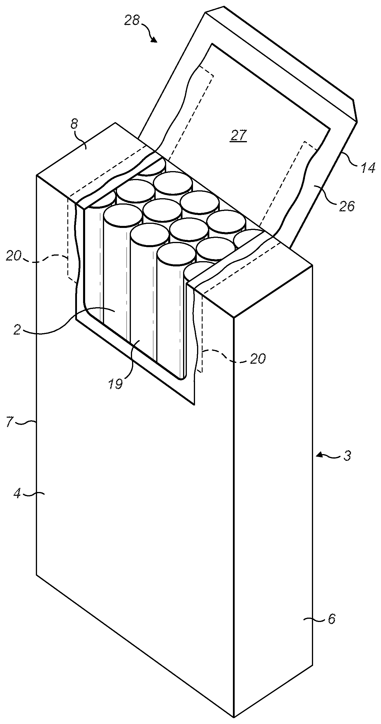
[0040] FIG. 1 shows a wrapped bundle 1 of tobacco industry products, for example smoking articles. In this example, the tobacco industry products are cigarettes 2.
[0041] The wrapped bundle 1 comprises a flexible and tearable barrier material 3 wrapped around a group of cigarettes 2, for example twenty cigarettes as shown. The cigarettes 2 are arranged in rows such that the overall shape of the wrapped bundle 1 is substantially cuboid, or parallelepiped in shape.
[0042] The barrier material 3 comprises a major surface 4, a rear surface 5, opposing side surfaces 6, 7 and an upper end surface 8. The wrapped bundle 1 as shown in the accompanying drawings has square edges but it will be appreciated that the edges may also be rounded or chamfered.
[0043] As shown in FIG. 1, the major surface 4 is provided with a starting cut 9. The major surface 4 is at least partially cut through in a `U` shape. The starting cut 9 comprises a first or central cut line 10 extending transversely across the major surface 4 in a direction between the opposing side surfaces 6, 7 and second and third cut lines 11, 12 extending for a short distance from the ends of the first cut line 10 in a longitudinal direction that extends towards the upper end surface 8 of the barrier material 3. The starting cut 9 defines a tab 13 formed by the first, second and third cuts 10, 11, 12.
[0044] The starting cut 9 may comprise other shapes. For example, the starting cut 9 may incorporate or be formed by a curved shape.
[0045] An adhesive label 14 is adhered to the barrier layer 3 such that it covers and seals the starting cut 9.
[0046] The adhesive label 14 shown in FIG. 1 extends from the major surface 4 of the barrier material 3, over a front end edge 15 and onto the upper end face 8 of the barrier material 3. The adhesive label 14 may also extend over a rear end edge 16 onto the rear face 5 of the barrier material 3, as shown in FIG. 1.
[0047] Also shown in FIG. 1, the adhesive label 14 comprises a pull tab 17. When a user pulls on the pull tab 17 in a direction away from the major surface 4 the adhesive label 14 peels off the front face 4 and pulls on the tab 13 defined by the starting cut 9.
[0048] As the tab 13 is pulled in response to pulling on the pull tab 17, tears propagate through the barrier material 3 of the major surface 4, starting from the end 11a, 12a of each of the second and third cuts 11, 12. Ideally, the tears propagate along a direct tear propagation path 18 (represented by dashed lines in FIG. 1), which is a linear extension of the second and third cuts, towards the upper end surface 8 of the barrier material 3. The direct tear propagation path 18 represents the shortest route in the major surface 4 between the end 11a, 12a of each of the second and third cuts 11, 12 and the front end edge 15 between the major surface 4 and the upper end surface 8. In particular, as a force is applied to the pull tab 17, the tears propagate in the major surface 4 of the barrier material 3, over the front end edge 15 and across the end surface 8. The front end edge 15 is formed by a fold line between the major surface 4 and the end surface 8.
[0049] Depending on the arrangement and extent of the adhesive label 14, and the extent to which a user pulls on the pull tab 17, the tears may propagate to a point on the end surface 8, to the rear end edge 16, or over the rear end edge 16 and onto the rear surface 5 of the wrapped bundle 1.
[0050] The above described application of a pulling force to the adhesive label 14 and the consequential tearing of the barrier material 3 creates an extraction opening 19, as shown in FIG. 2. The extraction opening 19 extends from the major surface 4, over the front end edge 15 and into the end surface 9 of the barrier material 3. The cigarettes 2 can be removed from the wrapped bundle 1 via the extraction opening 19 when the adhesive label 14 is in the position shown in FIG. 2.
[0051] In an alternative embodiment, the starting cut 9 comprises a line of weakness, rather than a through cut as described above. In this way, the application of a pulling force to the pull tab 17 will cause the line of weakness to tear and create a starting cut, from which the barrier material 3 will tear in order to form the extraction opening 19.
[0052] As indicated above, the direct tear propagation path 18 in the major surface 4 is essentially the shortest linear path extending from each end 11a, 12a of the second and third cut lines 11, 12 to the front end edge 15 in a longitudinal direction towards the upper end surface 8. However, depending on slight variations to the direction to which a pulling force may be applied to the tab 17, the tear may start to propagate from each end 11a,12a of the second and third cut lines 11, 12 along a tear propagation path that does not exactly correspond or align with the direct tear propagation path 18.
[0053] According to embodiments of the present invention, to provide control in the direction in which the tear propagates from each end 11a, 12a of the second and third cut lines 11, 12 of the starting cut 9, the barrier material 3 is provided with a weakened region 20, represented only in outline in FIGS. 1 and 2, that extends in a direction across the ends 11a, 12a of the cut-line 11, 12 in the major surface 4 and which serves to control the direction in which a tear propagates from each end 11a, 12a of the second and third cut-lines 11, 12 so that a tear that is propagating away from the direct tear propagation path 18 is guided back towards the direct tear propagation path 18. Alternatively, the the weakened region 20 may prevent the tear deviating any further away from the direct tear propagation path 18.
[0054] The weakened region 20 extends transversely across the major surface 4 of the barrier layer so that it bridges the direct tear propagation path 18, i.e. it extends in a lateral direction across the major surface 4 of the barrier material 3 in a direction between the opposing side surfaces 6,7. The width of each weakened region 20 is greater that the width of each of the second and third cut-lines 11, 12. In particular, the total width of the weakened region 20, in a direction extending between the opposing side surfaces 6, 7 is at least sufficient to ensure that a tear propagating from the ends 11a, 12a of the second and third cut lines 11, 12 as a result of pulling on the tab 17 will always meet the weakened region 20 and so be guided thereby, even when a tear propagating from each end 11a, 12a of the second and third cut lines 11, 12 is not propagating along the direct tear propagation path 18.
[0055] A separate weakened region 20 extends across the ends 11a, 12a of each of the second and third cut lines, as shown in FIGS. 1 and 2. However, it is envisaged that a single weakened region 20 could extend over the major surface 4 of the barrier layer and across ends 11a,12a of both the second and third cut lines 11, 12.
[0056] The weakened region 20 is spaced from each end 11a, 12a of the second and third cut lines 11, 12 so that a tear propagating from each end of the second and third cut lines 11, 12 will meet or intersect the weakened region 20 after a tear has been initiated. However, in some embodiments, the weakened region 20 may be positioned so that a direction in which a tear propagates from each end of the second and third cut lines is directly influenced and controlled by the weakened region 20 as soon as the tear has been initiated. For example, the weakened region 20 may extend over or below the ends 11a, 12a of the cut-lines 11,12, and the weakened region may extend directly from the ends 11a, 12a of the cut-lines 11, 12.
[0057] As shown in FIGS. 1 and 2, the weakened region 20 may extend from the major surface 4 of the barrier layer, over the front end edge 15 and across the upper end surface 8 to the rear end edge 16. However, the weakened region 20 may extend only partly across the upper end surface 8, or may terminate in the major surface 4 prior to reaching the front end edge 15. Preferably, the weakened region 20 extends so that the tear will be guided by the weakened region 20 over its full length.
[0058] In a preferred embodiment, the barrier layer is provided with the weakened region 20 on its inner surface, i.e. its surface that faces the smoking articles. However, it is also possible for the weakened region 20 to be formed on the outer surface, facing the adhesive label 14.
[0059] FIG. 3A shows the cut-line 9 and a part of the weakened region 20 according to a first embodiment of the invention in more detail. In particular, the weakened region 20 comprises a series of spaced parallel score lines 21 in the barrier material, each of which extend parallel to the direct tear propagation path 18 so that a tear propagating from the ends 11a, 12a of the cut line 11, 12 will intersect one of the score lines 21 if it deviates from the direct tear propagation path 18, which extends between two score lines 21. As each score line 21 presents a weakening in the major surface 4 of the barrier material 3, it forms a path of least resistance so that further pulling on the tab 13 will cause the tear to propagate along the score line 21 which has been intersected by the propagating tear. Thus, further propagation of the tear is guided by the score line 21 and prevents any further deviation of the tear from the direct tear propagation path 18 because the score lines 21 are parallel to the direct tear propagation path 18.
[0060] In an alternative arrangement, as shown in FIG. 3B, one of the score lines 21 may correspond and be in alignment with the direct tear propagation path 18 so that if the tear initially propagates from the end 11a, 12a of the second and third cut-lines 11, 12 along the direct tear propagation path 18, it will be guided by the score line 21 aligned with the direct tear propagation path 18 so that deviation of the tear from the direct tear propagation path 18 is prevented. Tearing along the direct tear propagation path 18 is also made easier as a result of the score line 21 that is aligned with it.
[0061] In a modified embodiment of FIG. 3A, shown in FIG. 3C, the score lines 21 extend below the ends 11a, 12a of the cut-lines 11, 12 so that the score lines 21 and the cut-lines 11, 12 overlap in a direction across the face of the barrier material. Similarly, FIG. 3D shows a modified embodiment of FIG. 3B, in which the score lines 21 extend below the ends 11a, 12a of the cut-lines 11, 12 and so that the one score line which lies on the direct tear propagation path 18 extends directly from the ends 11a, 12a of the cut-lines 11, 12. In either embodiment, it will also be appreciated that the score lines may be aligned with the ends 11a, 12a of the cut-lines, rather than overlap the ends 11a, 12a of the cut-lines 11, 12.
[0062] In another embodiment, as shown in FIG. 4, the weakened region 20 comprises score lines which together form an inverted Y-shape pattern in the major surface 4 of the barrier material 3. More specifically, the weakened region 20 comprises a first score line 22 and a second score line 23 that converge towards each other across the weakened region 20 and in a direction away from the cut line 11, 12 towards the end surface 9. The first and second score lines 22, 23 meet on the direct tear propagation path 18. A third line of weakness 24 extends from the point at which the first and second score lines 22, 23 meet on the direct tear propagation path 24 in a direction away from the second and third cut-lines 11, 12 towards the end surface 9. In a similar way to the previous embodiment, the ends 22a, 23a of the first and second score lines 22, 23 may be spaced from the ends 11a, 12a of the cut-line 9 in a the direction of the direct tear propagation path 18. Alternatively, the ends 22a, 23a may be aligned with the ends 11a, 12a, or extend below them so as to overlap in a direction extending across the face of the barrier layer.
[0063] It will be appreciated that the weakened region, provided by the first and second score lines 20,23, has a width greater than the width of the cut-line, i.e. the distance between the ends 22a, 23a of the score lines 22, 23 is much greater than the width of the cut-line 11, 12. As the mouth of the converging score lines is open in a direction facing the ends 11a, 12a of the cut-lines 11, 12, they extends across the end of said cut-line and control the direction of the tear propagating from the end 11a, 12a of the cut-line 11, 12, even if the tear is not following the line of the direct tear propagation path 18.
[0064] When a tear propagates from each end of the second and third cut lines 11, 12 in a direction other than along the direct tear propagation path 18, it will intersect one of the first and second score lines 22, 23. As the tab 13 continues to be pulled, the tear is guided by the intersected score line 22, 23, which forms a path of least resistance, in a direction towards the direct tear propagation path 18 until it reaches the direct tear propagation path at the point at which the first and second score lines 22, 23 meet each other. Once the tear has reached this point, further pulling on the tab 13 causes the tear to propagate along the direct tear propagation path 18 by the third score line 24, which forms a further path of least resistance for the tear to follow. This embodiment therefore has the advantage of guiding a tear that is deviating away from the direct tear propagation path 18 in a direction back to the direct tear propagation path 18 and then guiding it along the direct tear propagation path 18.
[0065] In a modified embodiment, the third score line 24 may be omitted so that the tear is guided to the point at which the first and second score lines 22, 23 meet on the direct tear propagation path 18. The tear then continues to propagate beyond this point without further guidance as the tab 13 is pulled further.
[0066] It will be appreciated that in the embodiments described above, the starting cut 9 is preferably a through cut in the major surface 4 of the barrier material 3. However, it may be a line of weakness formed by scoring or partially cutting the barrier material along the starting cut 9.
[0067] The adhesive label 14 may be at least partially adhered to the barrier material 3 with pressure sensitive adhesive. In particular, as shown in FIG. 1 and FIG. 2, the edges of the adhesive label 14 are offset from the cut lines 10, 11, 12 of the starting cut 9 and are therefore offset from the edges of the extraction opening 19 in the barrier material 3 after first opening of the wrapped bundle 1.
[0068] Therefore, the label 14 comprises an overlapping region 26 that surrounds the extraction opening 19. This overlapping region 26 of the adhesive label 14 may be provided with a coating of pressure sensitive adhesive so that the adhesive label 14 can be repositioned over the extraction opening 19 so that the pressure sensitive adhesive will re-adhere to the barrier material 3 and hold the adhesive label 14 in place over the extraction opening 19.
[0069] The underside surface of the adhesive label 14 may be entirely coated with pressure sensitive adhesive or, regions of the underside surface may be coated with permanent adhesive or no adhesive, in addition to the pressure sensitive adhesive in the overlapping region 26.
[0070] The torn section 27 of the barrier material 3, which has been separated from the remainder of the barrier material 3 to form the extraction opening 19, remains adhered to the adhesive label 14 as shown in FIG. 2.
[0071] The torn section 27 may be attached to the adhesive label 14 by pressure sensitive adhesive, or by a region of permanent adhesive provided between the torn section 27 and the adhesive label 14. If the torn section 27 is attached to the adhesive label 14 by pressure sensitive adhesive then the pressure sensitive adhesive may have an increased coating weight in the region of the torn section 27 to prevent the torn section 27 from detaching from the adhesive label 14 during use. The strength of the adhesive that adheres the label 14 to the torn section 27 is such that the barrier layer 3 will tear. Separation of the torn section 27 from the adhesive label 14 is prevented.
[0072] Therefore, the adhesive label 14 and the torn section 27 of the barrier material 3 form a re-usable cover flap 28 for closing the extraction opening 19 after first opening. The pressure sensitive adhesive on the overlapping region 26 of the adhesive label 14 is used to reattach the cover flap 28 and the barrier material 3.
[0073] In another embodiment, the adhesive label 14 is provided with single-use adhesive in the overlapping region 26, so that the cover flap 28 can be repositioned over the extraction opening 19 but the adhesive label 14 will not re-adhere to the barrier material 3.
[0074] A part of the adhesive label 14 may be permanently adhered to the barrier material 3, so that the cover flap 28 is retained on the wrapped bundle 1 and cannot be completely removed. In other embodiments, the cover flap 28 may be removed completely from the wrapped bundle 1 on opening, by using single-use adhesive over the whole of the adhesive label 14, or by providing a tear-off line through the adhesive label 14.
[0075] In combination with the adhesive label 14 covering the starting cut 9, the front face 5, end face 9 and rear face 5, the wrapped bundle 1 is sealably closed prior to first opening by pulling on the pull tab 17.
[0076] FIG. 5 shows an inner frame 3o that holds the cigarettes 2 (see FIG. 2) and is wrapped by the barrier material 3 to form the wrapped bundle 1 shown in FIGS. 1 and 2. In other words, the inner frame 30 shown may be positioned between the cigarettes 2 and the barrier material 3.
[0077] The inner frame 30 comprises a front wall 31, a rear wall 32, opposing side walls 33, 34, a bottom wall 35 and a top wall 36, that correspond to the front face 4, rear face 5, opposing side faces 6, 7 and end faces 8, 9 of the wrapped bundle 1, once the inner frame 30 is wrapped in the barrier material 3. The inner frame 30 also comprises an aperture 37 formed in the end wall 36 and front wall 31 that is aligned with the above described extraction opening 19 after first opening of the wrapped bundle 1, as shown in FIG. 2.
[0078] In this example, the aperture 37 in the inner frame 30 extends partially across the top wall 36 and front wall 31 of the inner frame 30. Therefore, when the extraction opening 19 is formed it is aligned with the aperture 37 in the inner frame 30.
[0079] The inner frame 30 provides additional strength and supports the cigarettes 19. Moreover, if the wrapped bundle 1 is provided with a reduced internal pressure, for example a partial vacuum, then the inner frame 30 helps protect the cigarettes 2 against the crushing force of the atmospheric pressure acting on the outside of the wrapped bundle 1.
[0080] In some examples, the aperture 37 in the inner frame 30 is sized and positioned such that, after creating the extraction opening 19 in the barrier material 3 by pulling the adhesive label 17, at least some edges of the aperture 37 lie within the extraction opening 19.
[0081] The unbroken portion of the barrier material 3 preferably comprises a polymer, such as polypropylene. In this case, the fibres of the polymer material may be orientated and the barrier material 3 arranged such that the fibres are orientated in the direction of the desired tear lines. Therefore, the polymer material will tear more easily and more neatly as the adhesive label 14 is pulled to form the extraction opening 19. Otherwise, the polymer may stretch and deform as it is torn, leaving the extraction opening 19 with uneven edges and the adhesive label 14 may not easily seal over such edges.
[0082] The barrier material 3 may be cut or weakened by mechanical means, for example a rotary cutter having a fixed blade depth. Alternatively, the barrier material 3 may be cut using lasers with a preselected power and/or wavelength so that the laser cuts through only the desired parts of the layers of the barrier material 3.
[0083] The barrier material 3 may comprise a polymer (for example polypropylene), a metal foil, a metallised film (for example a metallised polymer) or any other flexible material suitable for packaging.
[0084] In a preferred example, the barrier material 3 comprises a three-layer laminate, having outer layers of orientated polypropylene and a middle layer of metal foil, for example aluminium foil.
[0085] As described hereinafter, to form the wrapped bundle 1 the barrier material 3 is wrapped around a group of cigarettes 19 and sealably closed. The cigarettes 19 may first be placed within an inner frame 30 to support and protect the cigarettes 19, and then the barrier material 3 can be wrapped around the inner frame 30 and group of cigarettes 19.
[0086] In one example, the edges of the barrier material 3 may be folded against the sides of the contents of the wrapped bundle 1, for example the inner frame 30, to form overlapping flaps that are sealed to each other, for example by using adhesive, heat seal or ultrasonic welding.
[0087] In another example, shown in FIG. 6, the barrier material 3 may be folded around the inner frame 30, and the ends of the barrier material 3 may be fin sealed.
[0088] In particular, the cigarettes 19 can be placed into the inner frame 30, for example by folding the inner frame 30 around the group of cigarettes 19, and then the barrier material 3 can be wrapped around the inner frame 30 as shown.
[0089] Firstly, edges of the barrier material 3 can be fin sealed to each other to form a first fin seal 45 that means the barrier material 3 is tubular around the inner frame 30. Then, the ends of the tubular barrier material 3 can also be fin sealed together, to form second and third fin seals 46, 47, as shown in FIG. 6. In this example, the fin sealed bundle 1 shown in FIG. 7 has the first fin seal 45 extending across the rear face 5 of the wrapped bundle 1, and the second and third fin seals 46, 47 extending along the opposing side faces 6, 7 of the wrapped bundle 1.
[0090] In another example, schematically shown in FIG. 8, the first fin seal 45 may be formed across the end face 8 of the wrapped bundle 1 which is opposite to the end face 9 having the adhesive label 14. The second and third fin seals 46, 47 can then be formed along the opposing side faces 6, 7 of the wrapped bundle 1.
[0091] In an alternative example, the first fin seal 45 may be formed across the front face 4 of the wrapped bundle 1, below the adhesive label 14.
[0092] As shown in FIG. 7, the fin seals 45, 46, 47 can be folded flat against the faces of the wrapped bundle 1.
[0093] A fin seal can be formed by pressing parts of the barrier material 3 together and applying heat and/or adhesive to join those parts of the barrier material 3 together. The heat may melt and/or fuse components of the barrier material 3 together.
[0094] A fin sealed wrapped bundle 1, as described above, will provide a strong hermetic seal capable of holding a pressure differential. For example, the interior of the wrapped bundle may be provided with a pressure above or below atmospheric pressure.
[0095] An increased pressure within the wrapped bundle 1 can be provided by adding air, or some other gas, or liquid, to the interior of the wrapped bundle 1 prior to forming the final seal. A reduced pressure, for example a partial vacuum, can be provided to the interior of the wrapped bundle 1 by extracting air prior to forming the final seal, for example by carrying out the wrapping and sealing process described with reference to FIG. 6 or FIG. 8 in a low pressure environment.
[0096] Alternatively, the wrapped bundle 1 may be provided with a one-way valve adapted to permit flow of air in one direction and not the other. The valve on the wrapped bundle 1 can then be provided with either a high pressure source or a low pressure source to move air into or out of the wrapped bundle 1.
[0097] Alternatively, the interior of the wrapped bundle 1 may be provided with a gas other than air, for example an inert gas. Additionally, other substances may be added to the interior of the pack as a liquid and allowed to evaporate within the wrapped bundle 1, for example to increase the pressure within the wrapped bundle 1.
[0098] As shown in FIGS. 9 and 10, the various examples of wrapped bundles 1 described with reference to FIGS. 1 to 8, may be received within a hinged-lid container 48 to provide a pack of cigarettes.
[0099] Alternatively, the wrapped bundle 1 may be provided as packaging itself, without any further pack outer or lid.
[0100] As shown in FIG. 9, the hinged-lid pack 48 has a base portion 49 having a parallelepiped form and which is adapted to receive the wrapped bundle 1 such that the wrapped bundle 1 protrudes from the base portion 49. In this position, the adhesive label 14, in particular the pull tab 17, is accessible for opening the wrapped bundle 1 and providing access to the cigarettes within.
[0101] A lid 50 is hingedly connected to the base portion 49 about a hinge 51. The lid 50 is pivotable between a closed position, where the lid 50 covers the wrapped bundle 1, and an open position, where the wrapped bundle 1 is exposed. FIG. 9 shows the lid 50 in the open position, such that a user can grasp the pull tab 17 on the adhesive label 14 and pull to tear the barrier material 3 and form an extraction opening.
[0102] In further embodiments, as shown in FIGS. 10 and 11, a part of the adhesive label 14, such as the pull tab 17, is attached to an inside face 52 of the lid 50, such that the adhesive label 14 lifts when the lid 50 is opened to provide the extraction opening, and is lowered when the lid 5o is closed, to cover the extraction opening.
[0103] The outside surface of the tab 17 may be attached directly to the inside face 52 of the lid front wall 53, as shown in FIG. 10. Alternatively, the tab 17 may be folded back and then attached to the inside face 52 of the lid front wall 53, as shown in FIG. 11.
[0104] In the embodiments of FIG. 10 and FIG. 11, attaching the pull tab 17 to the lid 50 has the advantage that the adhesive label 14 is pulled evenly and smoothly as the lid 50 is opened for the first time, which can help to control the tears in the barrier material 3.
[0105] The wrapped bundle 1 may be provided with an inner frame 55 positioned between the smoking articles 2 and the barrier material, to provide further rigidity to the wrapped bundle 1 and to provide a reaction surface to allow the adhesive label 14 to be pressed back down over the extraction opening.
[0106] As used herein, the term `pressure sensitive adhesive` means adhesives that are capable of being reused multiple times. That is, the adhesive is permanently tacky so that two components can be detached and reattached repeatedly.
[0107] As used herein, the term `permanent adhesive` means adhesives that are intended to strongly bond together two components such that they will not separate in normal use.
[0108] As used herein, the term "tobacco industry product" is to be understood as including smoking articles comprising combustible smoking articles such as cigarettes, cigarillos, cigars, tobacco for pipes or for roll-your-own cigarettes, (whether based on tobacco, tobacco derivatives, expanded tobacco, reconstituted tobacco, tobacco substitutes or other smokable material), electronic smoking articles such as e-cigarettes, heating devices that release compounds from substrate materials without burning such as tobacco heating products; and hybrid systems to generate aerosol from a combination of substrate materials, for example hybrid systems containing a liquid or gel or solid substrate.
[0109] In one embodiment, the tobacco industry product is a smoking article for combustion selected from the group consisting of a cigarette, a cigarillo and a cigar.
[0110] In one embodiment, the tobacco industry product is a non-combustible smoking article.
[0111] In one embodiment the tobacco industry product is a heating device which releases compounds by heating, but not burning, a substrate material. The material may be for example tobacco or other non-tobacco products, which may or may not contain nicotine. In one embodiment the heating device is a tobacco heating device.
[0112] In another embodiment the tobacco industry product is a hybrid system to generate aerosol by heating, but not burning, a combination of substrate materials. The substrate materials may comprise for example solid, liquid or gel which may or may not contain nicotine. In one embodiment, the hybrid system comprises a liquid or gel substrate and a solid substrate. The solid substrate may be for example tobacco or other non-tobacco products, which may or may not contain nicotine. In one embodiment the hybrid system comprises a liquid or gel substrate and tobacco.
[0113] The wrapper and bundle are described with reference to tobacco industry products, for example cigarettes. However, it will be appreciated that the wrapper may alternatively be used to wrap a bundle of non-tobacco industry related products or articles. For example, food products, electronics or other consumer goods.
[0114] In order to address various issues and advance the art, the entirety of this disclosure shows by way of illustration various embodiments in which the claimed invention(s) may be practiced and provide for a superior wrapper for a group of tobacco industry products. The advantages and features of the disclosure are of a representative sample of embodiments only, and are not exhaustive and/or exclusive. They are presented only to assist in understanding and teach the claimed features. It is to be understood that advantages, embodiments, examples, functions, features, structures, and/or other aspects of the disclosure are not to be considered limitations on the disclosure as defined by the claims or limitations on equivalents to the claims, and that other embodiments may be utilised and modifications may be made without departing from the scope and/or spirit of the disclosure. Various embodiments may suitably comprise, consist of, or consist essentially of, various combinations of the disclosed elements, components, features, parts, steps, means, etc. In addition, the disclosure includes other inventions not presently claimed, but which may be claimed in future.
* * * * *
D00000
D00001
D00002
D00003
D00004
D00005
D00006
D00007
D00008
D00009
D00010
D00011
XML
uspto.report is an independent third-party trademark research tool that is not affiliated, endorsed, or sponsored by the United States Patent and Trademark Office (USPTO) or any other governmental organization. The information provided by uspto.report is based on publicly available data at the time of writing and is intended for informational purposes only.
While we strive to provide accurate and up-to-date information, we do not guarantee the accuracy, completeness, reliability, or suitability of the information displayed on this site. The use of this site is at your own risk. Any reliance you place on such information is therefore strictly at your own risk.
All official trademark data, including owner information, should be verified by visiting the official USPTO website at www.uspto.gov. This site is not intended to replace professional legal advice and should not be used as a substitute for consulting with a legal professional who is knowledgeable about trademark law.