Eddy Current Separation Of Blanks For The Automated Destacking Of Aluminum Sheet
Dively; Randal ; et al.
U.S. patent application number 15/993460 was filed with the patent office on 2019-12-05 for eddy current separation of blanks for the automated destacking of aluminum sheet. This patent application is currently assigned to Ford Motor Company. The applicant listed for this patent is Ford Motor Company. Invention is credited to Seth Avery, Ralph Conrad, Randal Dively, Andrey Ilinich, Franco Leonardi, S. George Luckey, Jr., Patrick McCleer.
| Application Number | 20190366417 15/993460 |
| Document ID | / |
| Family ID | 68694986 |
| Filed Date | 2019-12-05 |

| United States Patent Application | 20190366417 |
| Kind Code | A1 |
| Dively; Randal ; et al. | December 5, 2019 |
EDDY CURRENT SEPARATION OF BLANKS FOR THE AUTOMATED DESTACKING OF ALUMINUM SHEET
Abstract
A method of separating blanks from a stack includes positioning a magnetic field generator in a fixed location proximate a peripheral edge of an upper portion of the stack, activating the magnetic field generator such that eddy currents are generated and result in a force vector in a direction away from a top-most blank of the stack, and pushing a blank, or multiple blanks, immediately below the top-most blank away from the top-most blank by the eddy currents.
| Inventors: | Dively; Randal; (Monroe, MI) ; Conrad; Ralph; (South Lyon, MI) ; Luckey, Jr.; S. George; (Dearborn, MI) ; Ilinich; Andrey; (Novi, MI) ; Leonardi; Franco; (Dearborn Heights, MI) ; Avery; Seth; (Livonia, MI) ; McCleer; Patrick; (Jackson, MI) | ||||||||||
| Applicant: |
|
||||||||||
|---|---|---|---|---|---|---|---|---|---|---|---|
| Assignee: | Ford Motor Company Dearborn MI |
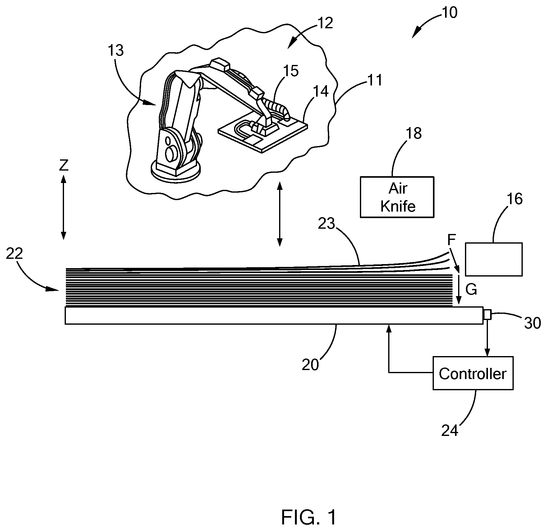
||||||||||
| Family ID: | 68694986 | ||||||||||
| Appl. No.: | 15/993460 | ||||||||||
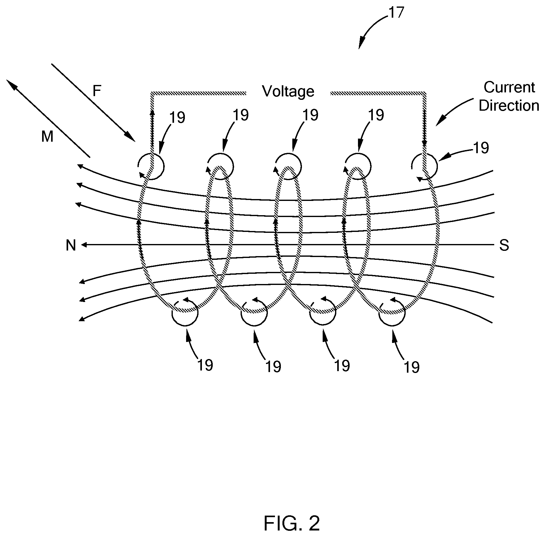
| Filed: | May 30, 2018 |
| Current U.S. Class: | 1/1 |
| Current CPC Class: | B21D 43/24 20130101 |
| International Class: | B21D 43/24 20060101 B21D043/24 |
Claims
1. A method of separating a blank from a stack of blanks comprising: positioning a magnetic field generator in a fixed location proximate a peripheral edge of an upper portion of the stack; activating the magnetic field generator such that eddy currents are generated and result in a force vector in a direction away from a top-most blank; and pushing, by the magnetic field generator, at least one blank immediately below the top-most blank away from the top-most blank after the top-most blank is lifted by an external device, wherein the magnetic field generator is disposed relative to the stack in a way such that the force vector is applied on the at least one blank to separate the at least one blank from the top-most blank before the top-most blank and the at least one blank are completely separated from remaining blanks of the stack.
2. The method according to claim 1, wherein the blanks are an aluminum alloy material.
3. The method according to claim 1, wherein the magnetic field generator is an electromagnet.
4. The method according to claim 1, wherein the magnetic field generator is a rotating assembly of permanent magnets having alternating north and south poles.
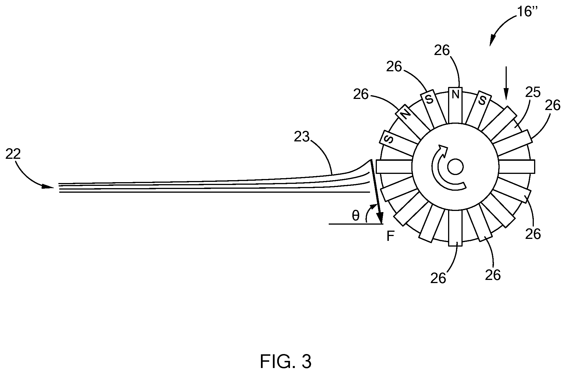
5. The method according to claim 1 further comprising injecting air into a side of the stack as the individual blanks are separated by the eddy currents.
6. The method according to claim 1, wherein a width of the blanks is between about 25 mm to about 3000 mm, a length of the blanks is between about 25 mm to about 3000 mm, a thickness of each blank is between about 0.5 mm to about 6.0 mm, and a height of the stack of blanks is between about 1 mm to about 2000 mm.
7. The method according to claim 1 further comprising a step of moving the top-most blank to a subsequent manufacturing operation.
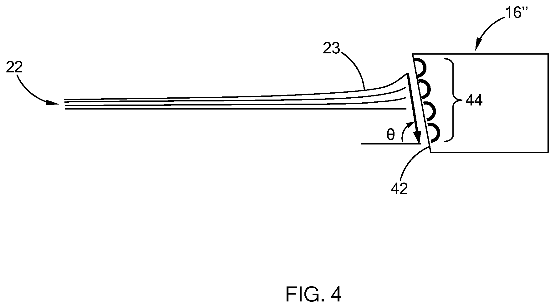
8. The method according to claim 1, wherein only one sheet at a time is displaced by the magnetic field generator.
9. The method according to claim 1, wherein the gravitational direction is between 90 degrees and 75 degrees as measured from a normal face of a blank.
10. An apparatus for separating blanks from a stack comprising: a fixed magnetic field generator; a jig configured to hold and translate the stack of blanks past the fixed magnetic generator such that a peripheral edge of an upper portion of the stack is continually positioned proximate the fixed magnetic field generator; and a position sensor for detecting a position of the jig, wherein eddy currents from the fixed magnetic field generator force an unwanted blank immediately below a top-most blank of the stack to be separated from the top-most blank of the stack and to fall with gravity after the top-most blank is lifted by an external device, and wherein the fixed magnetic field generator is disposed relative to the stack in a way such that the eddy currents separate the unwanted blank from the top-most blank before the top-most blank and the unwanted blank are completely separated from remaining blanks of the stack.
11. The apparatus according to claim 10, wherein the magnetic field generator includes a polyphase winding.
12. The apparatus according to claim 10, wherein the magnetic field generator is a rotating assembly of permanent magnets having alternating north and south poles.
13. The apparatus according to claim 10 further comprising an air knife configured to inject air into the stack as the unwanted blank is separated by the eddy currents.
14. The apparatus according to claim 10 further comprising a transport mechanism configured to move the top-most blank to a subsequent manufacturing operation.
15. The apparatus according to claim 14, wherein the transport mechanism comprises a plurality of suction cups configured to hold the top-most blank of the stack.
16. The apparatus according to claim 14, wherein the transport mechanism comprises a robot with an end effector to hold the stack of blanks.
17. The apparatus according to claim 10 further comprising a controller configured to transmit signals to the jig for translational movement.
18. The apparatus according to claim 17, wherein the position sensor is in communication with the controller to transmit the position of the jig to the controller.
19. The apparatus according to claim 10, wherein the stack of blanks is not injected with any current by way of physical contact.
20. The apparatus according to claim 10 wherein the eddy currents result in a force vector in a direction between 90 degrees and 75 degrees as measured from a normal face of a blank.
Description
FIELD
[0001] The present disclosure relates to a material handling machine and method, and more particularly to an apparatus and a method for separating blanks.
BACKGROUND
[0002] The statements in this section merely provide background information related to the present disclosure and may not constitute prior art.
[0003] In a material forming operation, such as a stamping operation, a stack of blanks is generally positioned in proximity to a stamping press and automatically fed into a stamping press by a material handling machine, such as a material handling robot. Tool and die surfaces of the stamping press receive the blanks and form the blanks into a desired shape. The robot includes an end-effector, which is moved to a position above the stack of blanks, grasps and lifts the uppermost blank from the stack, and feeds the uppermost blank into the stamping press.
[0004] To facilitate the grasping operation of the end-effector, the stack of blanks may be de-stacked or separated before the end-effector grasps the uppermost blank. The typical de-stacking method is not suitable for high-volume manufacturing cycle time which requires automated, rapid, and robust blank de-stacking. If two or more blanks are picked up by the robot, the system experiences a disruption and stops the production line, resulting in downtime of the manufacturing process.
[0005] Moreover, the typical de-stacking method is not suitable for picking up a variety of blank materials and of varying dimensions. For example, a typical de-stacking method that works with steel blanks may not work with aluminum blanks.
[0006] These issues associated with de-stacking equipment relative to material blanks, and the limitation of only certain materials being handled, are addressed by the present disclosure.
SUMMARY
[0007] In one form, a method of separating a blank from a stack of blanks is provided, which includes positioning a magnetic field generator in a fixed location proximate a peripheral edge of an upper portion of the stack, activating the magnetic field generator such that eddy currents are generated and result in a force vector in a direction away from a top-most blank, and pushing a blank, or multiple blanks, immediately below the top-most blank away from the top-most blank by the eddy currents.
[0008] In other features, the blanks are an aluminum alloy material, and the magnetic field generator is an electromagnet. The magnetic field generator is a rotating assembly of permanent magnets having alternating north and south poles. The method further includes injecting air into a side of the stack as the individual blanks are separated by the eddy currents, and moving the top-most blank to a subsequent manufacturing operation. Only one sheet at a time is displaced by the magnetic field generator. A width of the blanks is between about 25 mm to about 3000 mm, a length of the blanks is between about 25 mm to about 3000 mm, a thickness of each blank is between about 0.5 mm to about 6.0 mm, and a height of the stack of blanks is between about 1 mm to about 2000 mm. The gravitational direction is between 90 degrees and 75 degrees as measured from a normal face of a blank.
[0009] According to other features, the magnetic field generator includes a polyphase winding. The magnetic field generator is a rotating assembly of permanent magnets having alternating north and south poles. The apparatus may further include an air knife configured to inject air into the stack as the blank is separated by the eddy currents, a transport mechanism configured to move the top-most blank to a subsequent manufacturing operation, a controller configured to transmit signals to the jig for translational movement, and a position sensor in communication with the controller to transmit a position of the jig to the controller. In one form, the transport mechanism includes a plurality of suction cups configured to hold the top-most blank of the stack, and a robot with an end effector to hold the stack of blanks. Advantageously, the stack of blanks is not injected with any current by way of physical contact. In one form, the eddy currents result in a force vector in a direction between 90 degrees and 75 degrees as measured from a normal face of a blank.
[0010] Further areas of applicability will become apparent from the description provided herein. It should be understood that the description and specific examples are intended for purposes of illustration only and are not intended to limit the scope of the present disclosure.
BRIEF DESCRIPTION OF THE DRAWINGS
[0011] The present disclosure will become more fully understood from the detailed description and the accompanying drawings, wherein:
[0012] FIG. 1 is a schematic view of an apparatus for separating a blank from a stack of blanks constructed in accordance with the teachings of the present disclosure;
[0013] FIG. 2 is a schematic view of one form of a magnetic field generator operable with the apparatus of FIG. 1 according to the teachings of the present disclosure;
[0014] FIG. 3 is a schematic view of a stack of blanks and one variation of a magnetic field generator operable with the apparatus of FIG. 1 according to the teachings of the present disclosure;
[0015] FIG. 4 is a schematic view of a stack of blanks and another variation of a magnetic field generator operable with the apparatus of FIG. 1 according to the teachings of the present disclosure; and
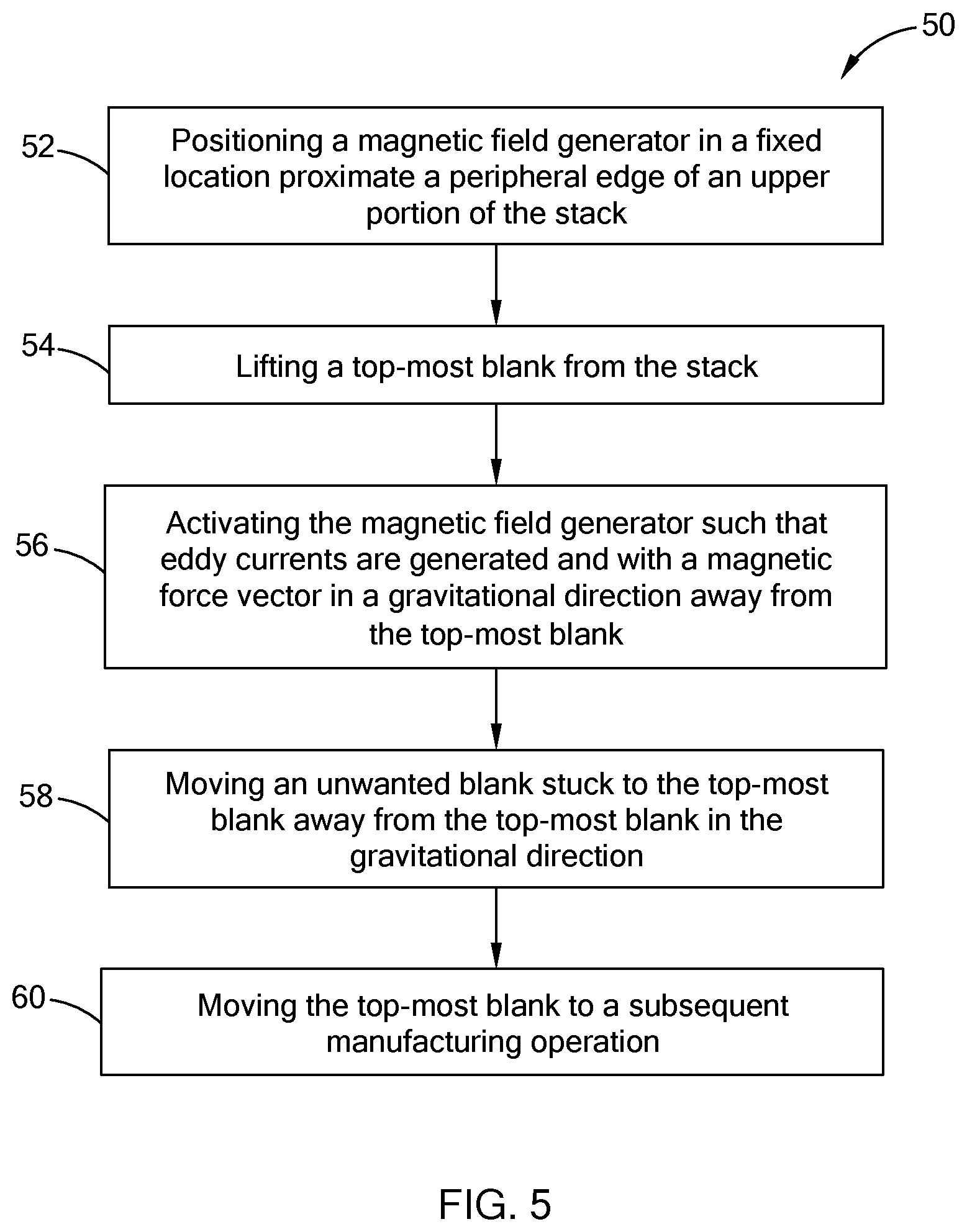
[0016] FIG. 5 is a flow diagram of a method for separating blanks from a stack in accordance with the teachings of the present disclosure.
[0017] Corresponding reference numerals indicate corresponding parts throughout the several views of the drawings.
DETAILED DESCRIPTION
[0018] The following description is merely exemplary in nature and is not intended to limit the present disclosure, application, or uses.
[0019] Referring to FIG. 1, a material handling apparatus 10 for separating a blank from a stack of blanks and for moving the separated blank to a desired location in accordance with the teachings of the present disclosure is shown. The material handling apparatus 10 in one form is used as part of a stamping press (not shown) in a manufacturing operation using conductive blanks, such as aluminum and steel alloys. Generally, the material handling apparatus 10 includes a transport mechanism, such as a robot 12, a fixed magnetic field generator 16, an optional air knife 18, and a jig 20 for holding and supporting the stack of blanks 22.
[0020] The robot 12 may include a robot arm 13 and an end-effector 14 attached to the robot arm 13. The end-effector 14 may include a plurality of suction cups supplied with a vacuum via a hose 15 such that the end-effector 14 applies a suction force and thereby securely grasps and moves a separated blank from the stack of blanks 22. Alternatively, the end-effector 14 may include a multi-fingered gripper or any conventional means that can grasp and move the separated blank. The separated blank is moved by the end-effector 14 and fed into a stamping press (not shown), with the robot arm 13 moving back and forth between the stamping press and the stack of blanks 22 until all of the blanks in the stack have been sequentially fed into the press. (Only portions of the robot 12 are shown via a schematic inset 11 for illustrative simplicity).
[0021] As described in greater detail below, the magnetic field generator 16 is used to remove unwanted blank(s) stuck to a top-most blank 23 when the top-most blank 23 is grasped by an end-effector 14 so that the top-most blank 23 can be separated from the remaining blanks in the stack of blanks 22 to avoid inadvertent separation of more than one blank by the end-effector 14. More specifically, the end-effector 14, with its suction force, may grasp more than one blank from the stack of blanks 22 at a time. The magnetic field generator 16 generates a repulsive force F to push any unwanted blank(s) that are stuck to the top-most blank 23 downward. The unwanted blanks that are stuck to the top-most blank 23 can be further separated with the assistance of gravitational force G, rather than separating individual blanks as with conventional blank separating equipment. Further, the individual blanks are not physically touched by any equipment/components of the material handling apparatus 10.
[0022] Referring to FIG. 2, the magnetic field generator 16 in one form is a solenoid 17, which employs a polyphase winding to generate a moving (translating) magnetic field M and eddy currents 19, which produce the force vector F that functions to separate an unwanted blank that is stuck to the top-most blank 23, from the top-most blank 23. In one form, the polyphase winding may be a three phase winding. The magnetic field generator 16 is fixed and is configured such that the force generated by the eddy currents 19 pushes any unwanted blank that is stuck to the top-most blank 23 downward as shown in FIG. 1, the separation of which is further assisted by the gravitational force G. The direction of the magnetic force produced by the eddy currents 19 of the magnetic field generator 16 is determined by a charge and vector product of the charge velocity and the magnetic field according to Equation 1:
F.sub.B=qv.times.B (Equation 1)
[0023] where:
[0024] F.sub.B=magnetic force vector
[0025] q=charge
[0026] V=velocity vector of the charge
[0027] B=magnetic field vector
[0028] Accordingly, the magnetic field generator 16 is configured such that the direction of the force of the eddy currents 19 to separate an unwanted blank from the top-most blank 23 is downward, in a gravitational direction G, as shown. The force F may be in the range of 5 lbs to 200 lbs depending on the application, and may vary further from these exemplary values.
[0029] The material handling apparatus 10 may optionally include a controller 24 for actuating the jig 20 to move the stack of blanks 22 up and down along a Z-direction. The controller 24 is configured to move the jig 20 and position the stack of blanks 22 to a predetermined height relative to the stationary magnetic field generator 16 for an optimum separation force between the unwanted blank that is disposed immediately below the top-most blank 23 from the top-most blank 23. The jig 20 moves the stack of blanks 22 from an elevated position and progressively upwardly along the Z-direction such that a peripheral edge of an upper portion of the stack is continually positioned proximate the fixed magnetic field generator 16. A position sensor 30 may be disposed at the jig 20 and in communication with the controller 24 to transmit a signal corresponding to a position of the jig 20 to the controller 24.
[0030] Optionally, the air knife 18 is configured to inject air into the stack of blanks 22 as the top-most blank 23 is sucked by the end-effector 14 and the blank immediately below the top-most blank 23 is separated from the top-most blank 23 by a repulsive force F resulting from the local eddy currents of the magnetic field generator 16. The robot 12 is configured to move the top-most blank 23, which has been separated from the stack of blanks 22, to a target site for a subsequent manufacturing operations.
[0031] Referring to FIG. 3, another form of a magnetic field generator 16' is shown that is disposed adjacent to the stack of blanks 22 and includes a rotor 25 and a plurality of magnets 26, which are permanent magnets, to form a rotating assembly. Similarly, the magnetic field generator 16' does not contact the stack of the blanks 22. The plurality of magnets 26 are arranged to extend in radial directions of the rotor 25 and are spaced apart in the circumferential direction of the rotor 25, with north (N) and south (S) poles alternately arranged.
[0032] Rotation of the magnets 26 with alternating polarities results in a constantly changing magnetic field, which induces an eddy current in a nearby conductor, i.e., within the edge of the blanks 22. A magnetic force is equal to the product of an electric current, a magnetic field, and a length of a given conductor, in this instance the blank immediately below the top-most blank 23. The interaction between the magnetic field generated by the magnet field generator 16 and the eddy current in the blanks 22 generates an opposing repulsive force F between the blanks 22 and the rotating magnets 22 that serves to move the edge of the blank immediately below the top-most blank 23 away from the top-most blank 23. The blank immediately below the top-most blank 23 then falls due to gravity. The repulsive force F is in a direction defining an angle .theta. relative to the front face of the blank 22, which is between 75.degree. and 90.degree. in one form of the present disclosure. The opposing repulsive force F produces a targeted "blank fanning" effect in which the generated magnetic force is produced in a controlled and targeted manner to separate the blanks 22.
[0033] The magnitude of the opposing repulsive force F depends on the rotational speed of the rotor 25, the magnetic field strength of the magnets 26, and the diameter of the rotor 25. Therefore, the repulsive force F resulting from the eddy currents and the magnetic field may be carefully tuned according to the specifications of the blanks 22 (e.g., size, thickness, material).
[0034] Referring to FIG. 4, another variant of the magnetic generator 16'' constructed in accordance with the teaching of the present disclosure includes an inclined surface 42 facing edges of the stack of blanks 22, and an array of electromagnets 44 mounted along the inclined surface 42 and disposed in close proximity to the edge of the blanks 22. Similarly, the magnetic field generator 16'' does not contact the edges of the stack of blanks 22. The array of electromagnets 44 are computer-controlled and are operable to induce eddy currents within the edges of the blanks 22 by changing the magnetic field generated by the array of electromagnets 44. The computer (not shown) controls the array of the electromagnets 44 such that the electromagnetic field moves in reference to the edge of the blanks 22, thereby generating an opposing repulsive force F between the blanks 22 and the array of electromagnets 44. The electromagnetic field moves at an angle .theta. between 90 and 75 degrees relative to the front face of the blanks 22. The opposing repulsive force F in the blank edge serves to push down the blank that is disposed immediately below the top-most blank. Again, the unwanted blank immediately below the top-most blank 23 is pushed down, in a gravitational direction. This feature is one among several that distinguishes the teachings of the present disclosure from those of the prior art. Further, the material handing apparatus 10 and various forms of magnetic field generators 16/16'/16'' advantageously do not inject any current by way of physical contact into the stack of blanks 22, which results in a simpler and more efficient operation to separate and move blanks throughout various manufacturing operations such as stamping.
[0035] Referring now to FIG. 5, a method 50 of separating a blank from a stack of blanks 22 and moving a separated blank to a target site starts with positioning a magnetic field generator 16 in a fixed location proximate a peripheral edge of an upper portion of the stack in step 52. A top-most blank is lifted by, for example, an end-effector in step 54. The magnetic field generator is activated such that eddy currents and a magnetic force vector (i.e., a repulsive force) in a gravitational direction away from the top-most blank 23 are generated in step 56. In one form, the gravitational direction is between 90 degrees and 75 degrees as measured from a front face of a blank, and as illustrated in FIGS. 2 and 3. Therefore, an unwanted blank that is stuck to the top-most blank 23 is moved away from the top-most blank 23 in the gravitational direction in step 58. Concurrently and optionally, air may be injected into the stack as individual blanks are separated by the repulsive force resulting from the eddy currents. Finally, the top-most blank 23 that is separated from the stack is moved to a subsequent manufacturing operation, which may be by the robot 12 shown in FIG. 1 in step 60.
[0036] The blanks 22 may be any conductive materials where eddy currents can be induced, such as aluminum alloys and steel alloys. In one form of high-volume automotive production, a width of the blanks is between about 25 mm to about 3000 mm, a length of the blanks is between about 25 mm to about 300 mm, a thickness of each blank is between about 0.5 mm to about 6.0 mm, and a height of the stack of blanks is between about 6 mm to about 2000 mm.
[0037] The apparatus and the method of the present disclosure are intended to eliminate the need for compressed air, dimple patterns, or other typical methods to facilitate separation of the blanks in stamping or other operations.
[0038] The description of the disclosure is merely exemplary in nature and, thus, variations that do not depart from the substance of the disclosure are intended to be within the scope of the disclosure. Such variations are not to be regarded as a departure from the spirit and scope of the disclosure.
* * * * *
D00000
D00001
D00002
D00003
D00004
D00005
XML
uspto.report is an independent third-party trademark research tool that is not affiliated, endorsed, or sponsored by the United States Patent and Trademark Office (USPTO) or any other governmental organization. The information provided by uspto.report is based on publicly available data at the time of writing and is intended for informational purposes only.
While we strive to provide accurate and up-to-date information, we do not guarantee the accuracy, completeness, reliability, or suitability of the information displayed on this site. The use of this site is at your own risk. Any reliance you place on such information is therefore strictly at your own risk.
All official trademark data, including owner information, should be verified by visiting the official USPTO website at www.uspto.gov. This site is not intended to replace professional legal advice and should not be used as a substitute for consulting with a legal professional who is knowledgeable about trademark law.