Expandable Threaded Adaptor For Threadless Shell
HAWKINS; Charles W.
U.S. patent application number 16/478092 was filed with the patent office on 2019-12-05 for expandable threaded adaptor for threadless shell. This patent application is currently assigned to Cummins Filtration IP, Inc.. The applicant listed for this patent is CUMMINS FILTRATION IP, INC.. Invention is credited to Charles W. HAWKINS.
| Application Number | 20190366248 16/478092 |
| Document ID | / |
| Family ID | 62978629 |
| Filed Date | 2019-12-05 |


| United States Patent Application | 20190366248 |
| Kind Code | A1 |
| HAWKINS; Charles W. | December 5, 2019 |
EXPANDABLE THREADED ADAPTOR FOR THREADLESS SHELL
Abstract
A filter assembly comprising a housing defining an internal volume. The housing comprises a first coupling member formed in a housing first end of the housing. The housing first end is threadless. The filter assembly further comprises a filter head. The filter head comprises a first thread formed on a surface thereof. The filter assembly further comprises an adapter. The adapter comprises a second coupling member formed on an adapter first end of the adapter. The second coupling member engages the first coupling member formed in the housing first end so as to removably couple the adapter and the housing. A second thread is formed on the adapter first end. The second thread engages the first thread formed in the filter head so as to removably couple the adapter and the filter head.
| Inventors: | HAWKINS; Charles W.; (Sparta, TN) | ||||||||||
| Applicant: |
|
||||||||||
|---|---|---|---|---|---|---|---|---|---|---|---|
| Assignee: | Cummins Filtration IP, Inc. Columbus IN |
||||||||||
| Family ID: | 62978629 | ||||||||||
| Appl. No.: | 16/478092 | ||||||||||
| Filed: | January 19, 2018 | ||||||||||
| PCT Filed: | January 19, 2018 | ||||||||||
| PCT NO: | PCT/US2018/014401 | ||||||||||
| 371 Date: | July 15, 2019 |
Related U.S. Patent Documents
| Application Number | Filing Date | Patent Number | ||
|---|---|---|---|---|
| 62450263 | Jan 25, 2017 | |||
| Current U.S. Class: | 1/1 |
| Current CPC Class: | B01D 35/306 20130101; B01D 2201/342 20130101; B01D 29/21 20130101; B01D 2201/4092 20130101; B01D 2201/295 20130101; B01D 35/30 20130101 |
| International Class: | B01D 35/30 20060101 B01D035/30; B01D 29/21 20060101 B01D029/21 |
Claims
1. A filter assembly, comprising: a housing defining an internal volume, the housing comprising a first coupling member formed on an outer surface on a housing first end of the housing, the housing first end being threadless; a filter head comprising a first thread formed on a surface thereof; and an adapter comprising: a second coupling member formed on an internal surface on an adapter first end of the adapter, the second coupling member engaging the first coupling member formed in the housing first end so as to removably couple the adapter and the housing, and; a second thread formed on an external surface on the adapter first end, the second thread engaging the first thread formed in the filter head so as to removably couple the adapter and the filter head.
2. The filter assembly of claim 1, wherein the first thread is formed on an internal surface of the filter head.
3. (canceled)
4. The filter assembly of claim 1, wherein the second coupling member comprises one of a protrusion and a detent, and wherein the first coupling member comprises the other of the protrusion and the detent.
5. The filter assembly of claim 1, wherein the adapter further includes at least one segmented section, the at least one segmented section formed on the adapter first end, the at least one segmented section allowing for flex in the adapter to receive the housing.
6. The filter assembly of claim 1, wherein the second thread is formed on an external surface on the adapter first end and comprises a reinforcing member.
7. The filter assembly of claim 1, further comprising: a filter element positioned within the internal volume of the housing, the filter element comprising: filter media; and a first end cap coupled to a filter media first end of the filter media, the first end cap comprising: a base, and a first end cap flange positioned about a periphery of the base, the first end cap flange extending from the base away from the filter element; and a first end sealing member positioned between an outer surface of the first end cap flange and an inner surface of the housing first end, the first end sealing member forming a seal between the housing and the first end cap.
8. The filter assembly of claim 1, wherein the adapter is permanently connected to the housing.
9. An adapter for a separator filter assembly, comprising: an adapter body; a first coupling member formed on an adapter first end of the adapter body, the first coupling member configured to engage a second coupling member formed on an outer surface of a housing first end of a housing so as to removably couple the adapter and the housing; and a third coupling member formed on an external surface of the adapter first end, the third coupling member configured to engage a fourth coupling member formed in a filter head so as to removably couple the adapter and the filter head.
10. The adapter of claim 9, wherein the first coupling member formed on the adapter first end comprises a protrusion that is formed on an internal surface on the adapter first end.
11. The adapter of claim 9, wherein the third coupling member and the fourth coupling member each comprise a threaded coupling member.
12. The adapter of claim 9, further comprising at least one segmented section formed on the adapter first end, the at least one segmented section allowing for flex in the adapter to receive the housing.
13. The adapter of claim 9, wherein the third coupling member formed on the adapter first end is disposed radially along an outside circumferential surface of the adapter.
14. The adapter of claim 9, wherein the first coupling member formed on the adapter first end is disposed radially along an inside circumferential surface of the adapter.
15. The adapter of claim 9, further comprising: a plurality of indentations formed on an outer surface of the adapter, the plurality of indentions being axial indentations defined circumferentially about adapter, the plurality of indentations facilitating gripping for coupling and/or uncoupling of the adapter by a user.
16. The adapter of claim 9, further comprising an outer flange extending circumferentially along an outside surface of the adapter, the third coupling member configured to connect to the filter head is disposed on the outer flange.
Description
CROSS-REFERENCE TO RELATED APPLICATIONS
[0001] The present application claims priority to U.S. Provisional Patent Application, No. 62/450,263, filed Jan. 25, 2017 and the contents of which are incorporated herein by reference in its entirety and for all purposes.
TECHNICAL FIELD
[0002] The present application relates generally to fluid filtration systems. More particularly, the present application relates to fuel water separator filter assemblies.
BACKGROUND
[0003] Internal combustion engines generally combust a mixture of fuel (e.g., diesel, gasoline, natural gas, etc.) and air. Prior to entering the engine, the fuel is typically passed through a filter element to remove particulate matter (e.g., dust, metal particles, debris, etc.) from the fuel prior to combustion. Similarly, lubricant or lube (e.g., engine oil) provided to the engine may also be passed through a filter element so as to remove particulate matter from the lube before communicating to the engine. The fuel or oil may include water, which may accumulate in the filter and may have to be removed.
[0004] Various filter assemblies generally comprise a nut plate positioned on an end of a housing of the filter assembly, with such nut plates providing a mechanism for coupling of a filter head to a first end of the housing of the filter assembly, or coupling of a cover or bowl to a second end of the filter housing. Such nut plates introduce additional parts into the filter assembly and may increase manufacturing complexity and manufacturing cost of such filters. Additionally, the filter is configured for a rotatable and detachable connection to the head and/or bowl, by way of threaded connections. Due to this direct connection, the filter typically must be of a certain type and/or size in order to reliably connect to the head and/or bowl. Consequently, larger shell diameters and increases in wall thickness can prove to be very challenging for the shell suppliers to adapt to, and the alternate design option of roll threading to accommodate these changes is expensive.
SUMMARY
[0005] Various embodiments provide for a filter assembly comprising a housing defining an internal volume. The housing comprises a first coupling member formed in a housing first end of the housing. The housing first end is threadless. The filter assembly further comprises a filter head. The filter head comprises a first thread formed on a surface thereof. The filter assembly further comprises an adapter. The adapter comprises a second coupling member formed on an adapter first end of the adapter. The second coupling member engages the first coupling member formed in the housing first end so as to removably couple the adapter and the housing. A second thread is formed on the adapter first end. The second thread engages the first thread formed in the filter head so as to removably couple the adapter and the filter head.
[0006] Further embodiments provide for an adapter for a separator filter assembly (such as a fuel water separator filter assembly). The adapter comprises a first coupling member formed on an adapter first end of the adapter body. The first coupling member is configured to engage a second coupling member formed in a housing first end of a housing so as to removably couple the adapter and the housing. A third coupling member is formed on the adapter first end. The third coupling member is configured to engage a fourth coupling member formed in a filter head so as to removably couple the adapter and the filter head.
[0007] These and other features, together with the organization and manner of operation thereof, will become apparent from the following detailed description when taken in conjunction with the accompanying drawings, wherein like elements have like numerals throughout the several drawings described below.
BRIEF DESCRIPTION OF THE DRAWINGS
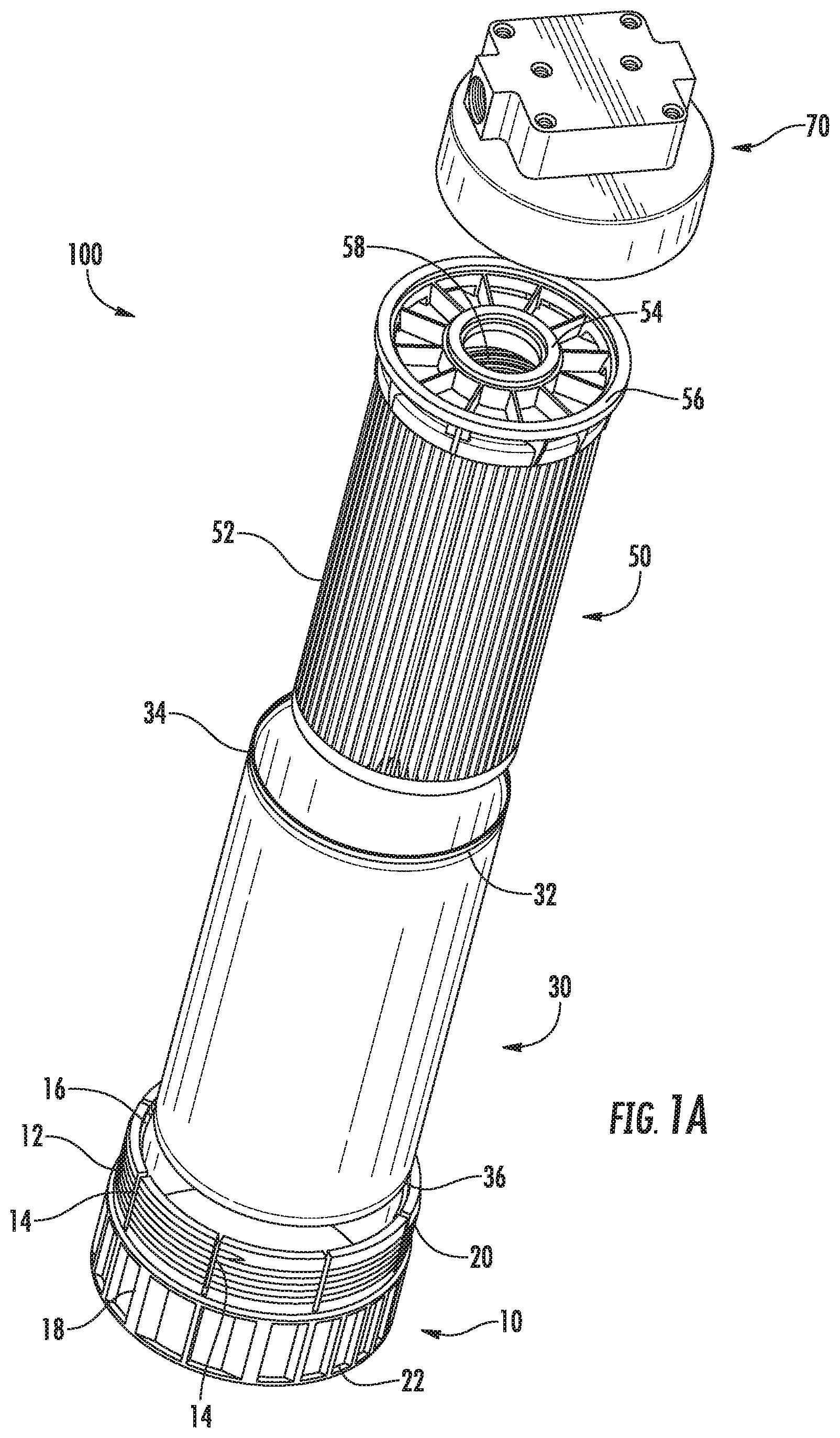
[0008] FIG. 1A is an exploded perspective view of a filter assembly, according to an example embodiment.
[0009] FIG. 1B is an assembled perspective view with a detached filter head of the filter assembly of FIG. 1A.
[0010] FIG. 1C is a front plan view with an attached filter head of a filter assembly.
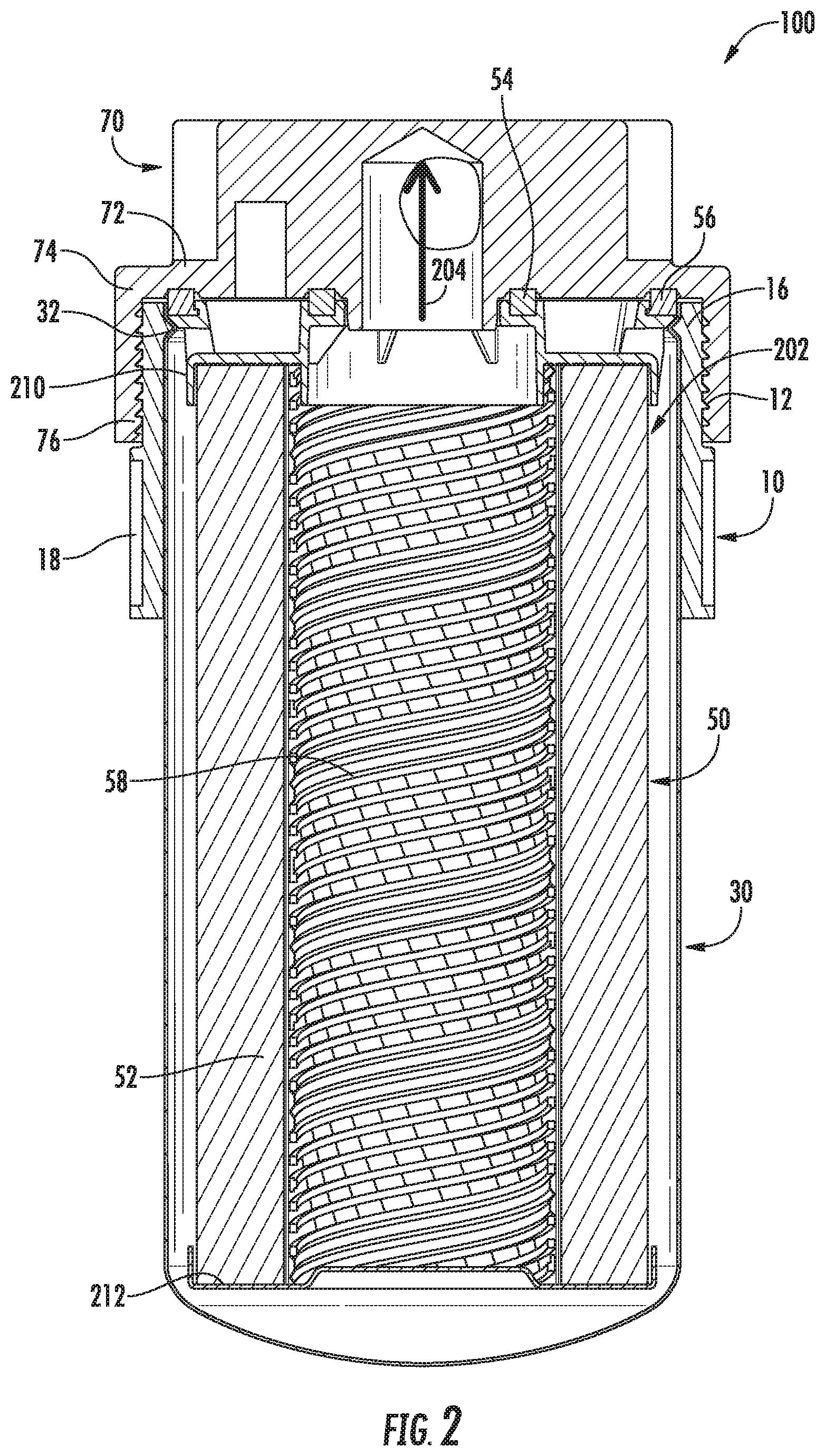
[0011] FIG. 2 is a cross-sectional view of the assembled filter assembly of FIG. 1C.
[0012] FIG. 3 is a partial cross-sectional exploded view of a section of the filter assembly of FIG. 2.
DETAILED DESCRIPTION OF VARIOUS EMBODIMENTS
[0013] Embodiments described herein relate generally to a system and method for securing a housing to a filter head without the use of a threaded connection. Generally, the housing has at least one detent (e.g., protrusion) feature formed in a top or first end of the housing, a filter head, having a first thread formed on an internal surface of the filter head; and an adapter configured to be removably coupled to the housing and the filter head.
[0014] Embodiments of the filter assembly described herein comprise an adapter that includes an interior facing coupling member for securing a housing and an exterior facing coupling member to a filter head without the use of a threaded connection directly between the housing and the filter head. The adapter can include both male and female coupling members may provide benefits including, for example: (1) allowing direct coupling of a housing to a threaded filter head, thereby allowing any housing to be used in a spin-on filtration system; (2) providing at least one segmented section which allow for flex in the structure of the adapter, thereby easing housing installation in the adapter and allowing for a plurality of coupling members to be used (e.g., snap fit, detent fit, etc.); (3) a secure sealing surface between the filter head and adapter; (4) applying a vertical load on the sealing gaskets without the addition of the torsional twist commonly present with spin on products when the adapter is engaged with the housing; and (5) reducing a manufacturing cost of assembly of the filter assembly by reducing the number of parts included in the filter assembly and allowing flexibility in the usable housing types.
[0015] FIG. 1A is an exploded perspective view of a filter assembly 100. FIG. 1B is an assembled perspective view of the filter assembly 100 with a detached filter head. FIG. 1C is a front plan view of a filter assembly 100 with an attached filter head. The filter assembly 100 comprises a housing 30, a filter element 50, an adapter 10, and a filter head 70. In the embodiment shown in FIGS. 1A-C, the filter assembly 100 is a fuel filter for the filtration of fuel. However, the filter assembly 100 is not limited to the filtration of fuel and may be used for the filtration of other fluids, such as lube, oil, air, or the like. For example, the filter assembly 100 may be configured to remove water contained in a fuel, such as a diesel fuel, before the fuel is introduced into an engine, such as a diesel engine. In addition, the filter assembly 100 is not limited to a fuel water separator filter and may be alternatively configured to function as different types of filters, including, but not limited to, suction side filters.
[0016] The filter head 70 includes a fluid inlet, which allows a fluid to be filtered to flow into the filter element 50, and a fluid outlet, which allows a filtered fluid to flow out of the filter element 50. The filter head 70 includes a filter head base 72 and a filter head sidewall 74 extending from an outer periphery of the filter head base 72. The filter head sidewall 74 extends from an outer periphery of the filter head base 72 towards the housing 30. The filter head 70 has first thread 76 on an inner surface of the filter head sidewall 74. The first thread 76 is structured to removably engage a second thread 12 of the adapter 10, so as to be coupled to a first end 20 of the adapter 10.
[0017] The filter element 50 may comprise a spin-on filter that includes a housing 30 and a filter element 50. In some embodiments, the filter element 50 is permanently affixed or installed within the housing 30. The filter element 50 includes a filter media 52 that is configured to filter the fluid. The filter media 52 comprises a porous material having a predetermined pore size and is configured to filter particulate matter from a fluid such as air flowing therethrough. The filter media 52 may comprise pleated media, corrugated media, fluted media, or the like. Disposed within the center of the filter media 52 may be a center tube 58. The center tube 58 may be configured to support the filter media 52 and/or allow the flow of fluid through the filter media 52. The center tube 58 may comprise a plurality of apertures so as to allow the fluid (e.g., air, fuel, oil etc.) to flow into the filter channel after passing through the filter media 52. The center tube 58 may be formed from plastic, metals or any other suitable material.
[0018] The filter element 50 includes an inner sealing member 54 and an outer sealing member 56 to provide a radial seal with the filter head 70 and/or the adapter 10. In some embodiments, the seal formed by the inner sealing member 54 and the outer sealing member 56 may comprise a "leak-tight" seal or a "substantially" leak-tight seal. As used herein, the term "leak-tight" is understood to encompass both a hermetic seal (i.e., a seal that is gas-impervious) as well as a seal that is liquid-impervious. The term "substantially" when used in connection with "leak-tight" is intended to convey that, while total fluid imperviousness is desirable, some minimal leakage due to manufacturing tolerances, or other practical considerations (such as, for example, the pressure applied to the seal and/or within the fluid), can occur even in a "substantially leak-tight" seal. In some arrangements, one or both of the inner sealing member 54 and the outer sealing member 56 may comprise O-rings.
[0019] The housing 30 defines an internal volume within which the filter element 50 is positioned. The housing 30 may be formed from a strong and rigid material, for example plastics (e.g., polypropylene, high density polyethylene, polyvinyl chloride, etc.), metals (e.g., aluminum, stainless steel, etc.), or any other suitable material. In particular embodiments, the housing 30 may comprise a cylindrical housing having generally a circular cross-sectional. In other embodiments, the housing 30 may have any suitable shape, for example square, rectangular, polygonal, etc.
[0020] The housing 30 comprises a housing first end 34 and a housing second end 36. The housing first end 34 comprises first coupling member 32 on an outer surface thereof. In some arrangements, the first coupling member 32 comprises a female end to a male-female coupling member pair, configured to receive a corresponding male coupling member (e.g., the second coupling member 16) of the adapter. As used herein, "housing first end" 34 is intended to refer to the area that comprises about twenty percent of the axial distance starting from the boundary that forms the top of the housing 30 member towards the boundary that forms the bottom of the housing 30. As used herein, "housing second end" 36 is intended to refer to the area that comprises about twenty percent of the axial distance starting from the boundary that corresponds to the bottom of the housing 30 member towards the boundary that corresponds to the top of the housing 30.
[0021] As shown in FIG. 1A, the first coupling member 32 comprises a detent element. In some arrangements, the first coupling member 32 is stamped into the housing 30. In other arrangements, the first coupling member 32 may be molded or otherwise formed into a sidewall of the housing 30. The first coupling member 32 is structured to removably engage a second coupling member 16 of the adapter 10, so as to be coupled to the first end 20 of the adapter 10.
[0022] The adapter 10 is configured to couple the housing 30 to the filter head 70 and filter element 50. The adapter 10 comprises the second thread 12 disposed externally on the first end 20, at least one segmented section 14 on the first end 20, second coupling member 16 disposed internally on the first end 20, and a plurality of indentations 18 disposed externally on a second end 22. In some arrangements, the second coupling member 16 comprises a male coupling member of a male-female coupling member pair, configured to receive a corresponding female coupling member (e.g., the first coupling member 32) of the housing.
[0023] Generally, the adapter 10 first receives a housing 30, whereby the adapter 10 is positioned circumferentially around the housing first end 34 of the housing. The filter head 70 receives the adapter 10, whereby the filter head 70 is circumferentially around the first end 20 of the adapter 10. Upon installation of the adapter 10 into the filter head 70, the filter head 70, adapter 10, housing 30, and filter element 50 are all removably coupled and form a "leak-tight" seal in various locations to facilitate the intake, filtering, and outflow of a fluid. As will be appreciated, the adapter 10 can be re-used with multiple different housings 30 (e.g., during filter servicing, the adapter 10 can be removed from a used housing 30, the used housing 30 is discarded, and the adapter 10 reattached to a new housing 30 having the mating member to the coupling member 32). The adapter 10 may be formed from a strong and rigid material, for example plastics (e.g., polypropylene, high density polyethylene, polyvinyl chloride, etc.), metals (e.g., aluminum, stainless steel, etc.), or any other suitable material
[0024] The at least one segmented section 14 is structured to allow flex in the first end 20 of the adapter 10 to facilitate coupling with the housing 30. The segmented section 14 allows for the adapter 10 to be inserted onto the housing 30 and provide the second coupling member 16 of the adapter 10 to the first coupling member 32 of the housing 30. The segmented section 14 may be radially disposed on the first end of the adapter 10. In some arrangements, the segmented section 14 includes eight segmented sections to provide greater flex and ease of installation over the housing 30
[0025] The second coupling member 16 comprises an internally facing coupling member disposed on the first end 20 (e.g., on an internal wall) and structured to couple with the first coupling member 32 of the housing 30. In addition, the second coupling member 16 extends radially inward. The second coupling member 16 may be formed during a deep draw machining process used to form the adapter 10. In some arrangements, the second coupling member 16 includes a male detent element. The connection between the adapter 10 and the housing 30, however, is not particularly limited to a detent element and may be any other appropriate detachable connections, such as a snap-fit connection or the like. As will be appreciated, when the expandable adapter 10 attaches to the housing 30 a vertical load is applied on the inner sealing member 54 and the outer sealing member 56 without the addition of the torsional twist commonly present--and required--with spin-on filter assemblies.
[0026] The second thread 12 comprises an externally facing thread disposed on the first end 20 (e.g., on an outer wall) and structured to engage with the first thread 76 of the filter head 70. In addition, the second thread 12 extends radially outward. In some arrangements, the threaded design is that of a buttress design, whereby the threads are positivity fixed by the threads disposed on the filter head 70. In those arrangements, there is no possibility of expansion of the threads and/or the adapter 10 that would loosen or reduce the force applied to the sealing members (e.g., gaskets). The second thread 12 may be formed during a deep draw machining process used to form the adapter 10. In some arrangements, the second thread 12 includes two threads per turn. The connection between the adapter 10 and the filter head 70, however, is not particularly limited to a threaded connection and may be any other appropriate detachable connections, such as a snap-fit connection or the like.
[0027] A plurality of indentations 18 or depressions may be formed on an outer surface of the adapter second end 22. For example, the plurality of indentations 18 may comprise axial indentations defined circumferentially about the adapter second end 22. The plurality of indentations 18 may be positioned with any suitable spacing between each adjacent indentation (i.e., any positioned at any suitable pitch). The plurality of indentations 18 may serve to facilitate gripping of the housing 30 for coupling and/or uncoupling the housing, for example to a filter head 70.
[0028] Referring to FIG. 1B, an assembled perspective view with a detached filter head 70 of the filter assembly 100 of FIG. 1A is shown. To install the adapter 10, the filter element 50 is first disposed in the housing 30 and secured within the housing, for example, through threaded, welded, or snap-fit connections. The housing 30--now comprising the filter element 50 in the internal volume of the housing 30--is then inserted into the adapter 10 such that the second coupling member 16 of the adapter 10 is disposed in the first coupling member 32 of the housing 30. The segmented section 14 of the adapter 10 allows for flex and aids in easing the installation of the adapter 10 over the housing 30. In some embodiments, the adapter 10 may be smaller (e.g. smaller in radius) than the housing 30. In those embodiments, the installation may be reversed, such that the adapter 10 is inserted into the housing 30 such that the second coupling member 16 of the adapter 10 is disposed in the first coupling member 32 of the housing 30.
[0029] Referring to FIG. 1C, an assembled front plan view of the filter assembly 100 of FIG. 1A is shown. To engage the adapter 10--now removably coupled to the filter element 50 and the housing 30--the adapter 10 is engaged with the filter head 70. The installation includes rotating the adapter 10 such that the first thread 76 of the filter head 70 is rotationally coupled with the second thread 12 of the adapter 10. As will be appreciated, the rotation of the adapter 10 into the filter head 70, compresses the segmented section 14 and the first end 20 of the adapter 10, thereby tightening the coupling of the second coupling member 16 of the adapter 10 disposed in the first coupling member 32 of the housing 30. Upon installation of the adapter 10 in the filter head 70, the various features coupled together are substantially flush with each other and can comprise a leak-tight" seal. As will be appreciated, when the adapter 10 is attached to the filter head 70, a vertical load is applied on the inner sealing member 54 and the outer sealing member 56 without the addition of the torsional twist. In some embodiments, the adapter 10 is larger (e.g., larger in radius) than the filter head 70. In those embodiments, the installation may be different, such that the adapter 10 is raised to the filter head 70, causing the filter head 70 be inserted into the adapter 10, and the adapter 10 is rotated such that the first thread 76 of the filter head 70 is rotationally coupled with the second thread 12 of the adapter 10.
[0030] Referring to FIG. 2, a cross-sectional view of the assembled filter assembly of FIG. 1C is shown. As shown, the various features coupled together are substantially flush with each other and comprise a leak-tight" seal. For example, the filter head 70 and adapter 10 are substantially flush via the thread coupling 12, 76 (e.g., male-female thread coupling). The adapter 10 and the housing 30 are substantially flush via the coupling members connection. The inner sealing member 54 and the outer sealing member 56 of the filter element 50 are sealably connected and flush with the filter head 70. The filter element 50 is securely disposed in the housing 30 through a first (e.g. top) end cap 210 and a second (e.g., bottom) end cap 212. In operation, the fluid flows into the filter head 70 through an inlet (not shown) and flows into 202 the housing 30. The fluid is filtered by the filter media 52 and travels radially through the filter media 52 into the center tube 58. The filtered fluid travels axially through the center tube 58 and flows out 204 of an outlet (not shown) in the filter head 70.
[0031] Referring to FIG. 3, a partial cross-sectional exploded view of a section of the filter assembly of FIG. 2 is shown. FIG. 3 provides an exploded view of the filter head 70 and adapter 10 being substantially flush via the thread coupling 12, 76; the adapter 10 and the housing 30 being substantially flush via the coupling members connection 16, 32; the inner sealing member 54 and the outer sealing member 56 of the filter element 50 being sealably connected and flush with the filter head 70; and the filter element 50 being securely disposed in the housing 30 through a first end cap 210 and a second end cap 212.
[0032] Expanding on the first end cap 210, the first end cap 210 is coupled to the top end of the filter media 52. The first end cap 210 may be formed from any suitable material, for example plastics, metals, rubber, reinforced rubber, polymers etc. The first end cap 210 may have a cross-section corresponding to the cross-section of the housing 30. The first end cap 210 comprises a base 302 and a first axial sidewall 304 extending from the base 302 towards the filter media 52. The first axial sidewall 304 is positioned inwardly from an outer edge of the base 302 of first end cap 210. For example the first axial sidewall 304 may comprise a circular sidewall extending from the base 302, and define a fluid outlet about the longitudinal axis of the filter assembly 100. The center tube 58 may be positioned in the outlet so as to provide an outlet conduit for the filtered fluid to be expelled from the housing 30.
[0033] The first end cap 210 further comprises a second axial sidewall 306 extending from the outer edge of the base 302 towards the filter media 52. The second axial sidewall 306 is spaced apart from the first axial sidewall 304. A filter media first end 310 may be positioned between the first axial sidewall 304 and the second axial sidewall 306. For example, the second axial sidewall 306 may be concentric with the first axial sidewall 304 and separated therefrom so that a circumferential space is defined between the first axial sidewall 304 and the second axial sidewall 306. The filter media first end 310 may be positioned in the space between the first axial sidewall 304 and the second axial sidewall 306. In some embodiments, the filter media first end 310 may be fixedly coupled to the base 302 of the first end cap 210, for example via an adhesive, heat bonded or fusion bonded to the first end cap 210. In some arrangements, the first end cap 210 includes a fluid inlet defined in the base 302 adjacent to the second axial sidewall 306 and a fluid outlet defined within the first axial sidewall 304.
[0034] Expanding on the outer sealing member 56, the outer sealing member 56 is positioned in a U-shaped channel between an outer surface of the first end cap flange, and an inner surface of the housing first end 34. The outer sealing member 56 forms a seal between the housing 30 and the first end cap 210, for example a leak-tight seal. The outer sealing member 56 may comprise a machine cut gasket having any suitable cross-sectional, for example rectangular cross-sectional or a circular cross-sectional (e.g., an O-ring). In some arrangements, the outer sealing member 56 comprises a square cut gasket having a rectangular or square cross-sectional shape.
[0035] The filter head 70 may further comprise a circumferential groove 308 defined on the filter head base 72, for example on a first surface of the filter head base 72 of the filter head 70 facing the first end cap 210. The circumferential groove 308 is structured to receive at least a portion of the outer sealing member 56, such that the outer sealing member 56 may seal each of the housing 30, the first end cap 210, adapter 10, and the filter head 70. The filter head sidewall 74 may also exert a radial force onto the housing first end 34 of the housing 30 which may push the housing flange towards the outer sealing member 56 and the first end cap 210, thereby enhancing the sealing provided by the outer sealing member 56.
[0036] Moreover, the housing 30 may also comprise a housing flange 38 positioned circumferentially about an outer periphery of the housing ledge. The housing flange 38 extends axially away from the first coupling member 32 of the housing 30 parallel to the longitudinal axis such that the housing ledge and the housing flange 38 define an L-shaped groove. At least a portion of the outer sealing member 56 is positioned within the L-shaped groove.
[0037] It should be noted that the term "example" as used herein to describe various embodiments is intended to indicate that such embodiments are possible examples, representations, and/or illustrations of possible embodiments (and such term is not intended to connote that such embodiments are necessarily extraordinary or superlative examples).
[0038] The term "coupled," "connected," and the like as used herein mean the joining of two members directly or indirectly to one another. Such joining may be stationary (e.g., permanent) or moveable (e.g., removable or releasable). Such joining may be achieved with the two members or the two members and any additional intermediate members being integrally formed as a single unitary body with one another or with the two members or the two members and any additional intermediate members being attached to one another.
[0039] References herein to the positions of elements (e.g., "top," "bottom," "above," "below," etc.) are merely used to describe the orientation of various elements in the figures. It should be noted that the orientation of various elements may differ according to other exemplary embodiments, and that such variations are intended to be encompassed by the present disclosure.
[0040] It is important to note that the construction and arrangement of the various example embodiments are illustrative only. Although only a few embodiments have been described in detail in this disclosure, those skilled in the art who review this disclosure will readily appreciate that many modifications are possible (e.g., variations in sizes, dimensions, structures, shapes and proportions of the various elements, various parameters, mounting arrangements, use of materials, colors, orientations, etc.) without materially departing from the novel teachings and advantages of the subject matter described herein. For example, elements shown as integrally formed may be constructed of multiple parts or elements, the position of elements may be reversed or otherwise varied, and the nature or number of discrete elements or positions may be altered or varied. The order or sequence of any process or method steps may be varied or re-sequenced according to alternative embodiments. Other substitutions, modifications, changes and omissions may also be made in the design, operating conditions and arrangement of the various example embodiments without departing from the scope of the concepts presented herein.
[0041] While this specification contains many specific implementation details, these should not be construed as limitations on the scope of any inventions or of what may be claimed, but rather as descriptions of features specific to particular implementations of particular inventions. Certain features described in this specification in the context of separate implementations can also be implemented in combination in a single implementation. Conversely, various features described in the context of a single implementation can also be implemented in multiple implementations separately or in any suitable subcombination. Moreover, although features may be described above as acting in certain combinations and even initially claimed as such, one or more features from a claimed combination can in some cases be excised from the combination, and the claimed combination may be directed to a subcombination or variation of a subcombination.
* * * * *
D00000
D00001
D00002
D00003
D00004
XML
uspto.report is an independent third-party trademark research tool that is not affiliated, endorsed, or sponsored by the United States Patent and Trademark Office (USPTO) or any other governmental organization. The information provided by uspto.report is based on publicly available data at the time of writing and is intended for informational purposes only.
While we strive to provide accurate and up-to-date information, we do not guarantee the accuracy, completeness, reliability, or suitability of the information displayed on this site. The use of this site is at your own risk. Any reliance you place on such information is therefore strictly at your own risk.
All official trademark data, including owner information, should be verified by visiting the official USPTO website at www.uspto.gov. This site is not intended to replace professional legal advice and should not be used as a substitute for consulting with a legal professional who is knowledgeable about trademark law.