Dose Limiting Mechanism
HEWSON; Karl James ; et al.
U.S. patent application number 16/332198 was filed with the patent office on 2019-12-05 for dose limiting mechanism. The applicant listed for this patent is NORTON HEALTHCARE LIMITED. Invention is credited to George BOSTOCK, Karl James HEWSON, George Robert Michael SAVELL.
| Application Number | 20190366007 16/332198 |
| Document ID | / |
| Family ID | 57234639 |
| Filed Date | 2019-12-05 |


View All Diagrams
| United States Patent Application | 20190366007 |
| Kind Code | A1 |
| HEWSON; Karl James ; et al. | December 5, 2019 |
DOSE LIMITING MECHANISM
Abstract
An injection device comprises a dose selector, rotatable by a user to set a dose to be ejected from the injection device and a drive assembly including a drive shaft (140) and a plunger element (145), the drive assembly being capable of providing an axial force for ejecting a dose of medicament from a medicament container. A dose limit nut (141) is provided which is rotationally coupled to but not axially coupled to said drive shaft. The plunger element is threaded so that the dose limit nut is engaged with said plunger element via said thread, in order to guide relative axial movement between the dose limit nut and the plunger element. The dose limit nut is provided with dose limiting endstops which are capable of limiting axial travel of said dose limit nut with respect to said plunger element, so as to limit maximum and minimum doses of medicament which can be set by the user. In addition, the dose limit nut comprises a last dose rotary endstop feature which prevents further rotation of said dose limit nut with respect to said drive shaft so as to prevent the user setting a dose that is greater than an injectable volume of medicament remaining in said medicament container.
| Inventors: | HEWSON; Karl James; (Cambridgeshire, GB) ; BOSTOCK; George; (Cambridgeshire, GB) ; SAVELL; George Robert Michael; (Cambridgeshire, GB) | ||||||||||
| Applicant: |
|
||||||||||
|---|---|---|---|---|---|---|---|---|---|---|---|
| Family ID: | 57234639 | ||||||||||
| Appl. No.: | 16/332198 | ||||||||||
| Filed: | September 11, 2017 | ||||||||||
| PCT Filed: | September 11, 2017 | ||||||||||
| PCT NO: | PCT/EP2017/072723 | ||||||||||
| 371 Date: | March 11, 2019 |
| Current U.S. Class: | 1/1 |
| Current CPC Class: | A61M 5/31535 20130101; A61M 5/31541 20130101; A61M 5/31511 20130101; A61M 5/31593 20130101; A61M 5/3129 20130101; A61M 5/31583 20130101; A61M 2005/3126 20130101; A61M 5/31553 20130101; A61M 5/2033 20130101; A61M 2005/3154 20130101; A61M 5/24 20130101; A61M 5/20 20130101; A61M 5/31551 20130101; A61M 5/31536 20130101; A61M 5/3157 20130101; A61M 2205/582 20130101 |
| International Class: | A61M 5/315 20060101 A61M005/315; A61M 5/20 20060101 A61M005/20 |
Foreign Application Data
| Date | Code | Application Number |
|---|---|---|
| Sep 12, 2016 | GB | 1615455.1 |
Claims
1. An injection device comprising: a. a dose selector, rotatable by a user to set a dose to be ejected from the injection device b. a drive assembly including a drive shaft and a plunger element configured to move a stopper so as to expel medicament through an opening in a medicament container, the drive assembly being capable of providing an axial force for ejecting a dose of medicament from the medicament container, c. a dose limit nut rotationally coupled to but not axially coupled to said drive shaft, wherein said plunger element is threaded so that the dose limit nut is engaged with said plunger element via said thread, in order to guide relative axial movement between the dose limit nut and the plunger element, wherein said dose limit nut is provided with dose limiting endstop features which are capable of limiting axial travel of said dose limit nut with respect to said plunger element, so as to limit maximum and minimum doses of medicament which can be set by the user, and wherein said dose limit nut further comprises a last dose rotary endstop feature which prevents further rotation of said dose limit nut with respect to said drive shaft so as to prevent the user setting a dose that is greater than an injectable volume of medicament remaining in said medicament container.
2. The injection device of claim 1 wherein one of said dose limiting endstop features also comprises said last dose rotary endstop feature.
3. The injection device of claim 1 wherein said dose limiting endstop features are engageable with one or more formations in said thread of the plunger element.
4. The injection device of claim 3 wherein the or each formation in said thread comprises a change in a depth of said thread.
5. The injection device of claim 1 wherein said drive shaft is arranged concentrically around a first longitudinal axis and wherein said medicament container and at least part of said drive assembly are arranged around a second longitudinal axis which is substantially parallel to but offset from the first longitudinal axis.
6. The injection device of claim 1 wherein the drive assembly comprises a rotational to axial coupling, where the drive assembly is rotationally drivable by a torsion spring and is arranged to provide said axial force for ejecting the dose from the medicament container.
7. The injection device of claim 5 wherein said plunger element comprises a rack and the drive assembly further comprises a worm gear engaged in said rack wherein rotation of said worm gear causes the rack to advance axially forward or backward with respect to said worm gear.
8. The injection device of claim 7 wherein said last dose rotary endstop feature is engageable with said worm gear.
9. The injection device of claim 7 wherein said worm gear is arranged around said first longitudinal axis and said rack is arranged around said second longitudinal axis.
10. The injection device of claim 7 wherein the drive assembly further comprises a worm gear rotational lock engageable with the worm gear, preferably engageable in a forward end thereof, so as to substantially prevent rotation of the worm gear.
11. The injection device of claim 10 wherein the worm gear rotational lock is disengageable from the forward end of the worm gear by being pushed axially forward by the drive shaft.
12. The injection device of claim 7 wherein the drive assembly further comprises means engageable between the drive shaft and the worm gear and which, when engaged, rotationally lock the drive shaft and worm gear together.
13. The injection device of claim 1 wherein said dose limit nut has a male thread and said plunger element has a female thread.
14. The injection device of claim 1 wherein said dose limit nut has a female thread and said plunger element has a male thread.
15. The injection device of claim 1 wherein said maximum dose is 100 IU.
16. The injection device of claim 1 wherein said minimum dose is 0 IU.
17. The injection device of claim 1 further comprising a medicament container.
18. The injection device of claim 17 further comprising a medicament contained in the medicament container.
19. The injection device of claim 18 wherein the medicament is selected from the group comprising: antipsychotic substances including risperidone, hormones, antitoxins, substances for the control of pain, immunosuppressives, substances for the control of thrombosis, substances for the control or elimination of infection, peptides, proteins, human insulin or a human insulin analogue or derivative, polysaccharide, DNA, RNA, enzymes, antibodies, oligonucleotide, antiallergics, antihistamines, anti-inflammatories, corticosteroids, disease modifying anti-rheumatic drugs, erythropoietin, or vaccines, for use in the treatment or prevention of rheumatoid arthritis, psoriatic arthritis, ankylosing spondylitis, ulcerative colitis, hormone deficiency, toxicity, pain, thrombosis, infection, diabetes mellitus, diabetic retinopathy, acute coronary syndrome, angina, myocardial infarction, atherosclerosis, cancer, macular degeneration, allergy, hay fever, inflammation, anaemia, or myelodysplasia, or in the expression of protective immunity.
Description
[0001] This disclosure relates to the field of a dose limiting mechanism for an injection device, preferably a reusable pen-injector injection device able to inject a selected dose of medicament.
BACKGROUND
[0002] Certain injection devices have a dose setting member, or dose selector, via which the user can select a desired dose of medicament to be delivered from a container of medicament associated with the injection device. The dose selector can commonly be actuated in one direction to increase the set dose ("dialling up") and actuated in another direction to decrease the set dose ("dialling down"). As the dose is dialled up or down, this correspondingly increases or decreases stored energy in the device (e.g. in a torsion spring).
[0003] During dose setting, it is desirable to be able to prevent a user from being able to dial up a dose that is larger than the quantity of medicament remaining in the container. This feature may be referred to as "last dose protection" or "last dose control".
[0004] Examples of injection devices with last dose protection features are described in WO2011/068531 (Becton Dickinson), WO01/19434 (Novo Nordisk) and WO2006/086983 (Novo Nordisk).
BRIEF SUMMARY OF THE DISCLOSURE
[0005] In accordance with an aspect of the present invention there is provided an injection device comprising: [0006] a. a dose selector, rotatable by a user to set a dose to be ejected from the injection device, [0007] b. a drive assembly including a drive shaft and a plunger element configured to move a stopper so as to expel medicament through an opening in a medicament container, the drive assembly being capable of providing an axial force for ejecting a dose of medicament from the medicament container, [0008] c. a dose limit nut rotationally coupled to but not axially coupled to said drive shaft, wherein said plunger element is threaded so that the dose limit nut is engaged with said plunger element via said thread, in order to guide relative axial movement between the dose limit nut and the plunger element, wherein said dose limit nut is provided with dose limiting endstop features which are capable of limiting axial travel of said dose limit nut with respect to said plunger element, so as to limit maximum and minimum doses of medicament which can be set by the user, and wherein said dose limit nut further comprises a last dose rotary endstop feature which prevents further rotation of said dose limit nut with respect to said drive shaft so as to prevent the user setting a dose that is greater than an injectable volume of medicament remaining in said medicament container.
[0009] The dose limit nut conveniently provides both last dose protection and maximum/minimum dose limiting with a single component, reducing the total number of component parts required and simplifying the injection device's design.
[0010] In certain embodiments, one of said dose limiting endstop features also comprises said last dose rotary endstop feature. The dose limiting endstop features may be engageable with one or more formations in said thread of the plunger element. The or each formation in said thread may comprise a change in a depth of said thread.
[0011] In certain embodiments, said drive shaft is arranged concentrically around a first longitudinal axis with said medicament container and at least part of said drive assembly are arranged around a second longitudinal axis which is substantially parallel to but offset from the first longitudinal axis.
[0012] Preferably, the drive assembly comprises a rotational to axial coupling, where the drive assembly is rotationally drivable by a torsion spring and is arranged to provide said axial force for ejecting the dose from the medicament container.
[0013] In certain embodiments, said plunger element comprises a rack and the drive assembly further comprises a worm gear engaged in said rack, wherein rotation of said worm gear causes the rack to advance axially forward or backward with respect to said worm gear. Preferably, said last dose rotary endstop feature is engageable with said worm gear. The worm gear may be arranged around said first longitudinal axis and said rack may be arranged around said second longitudinal axis. The drive assembly may further comprise a worm gear rotational lock engageable with the worm gear, preferably engageable in a forward end thereof, so as to substantially prevent rotation of the worm gear. The worm gear rotational lock may be disengageable from the forward end of the worm gear by being pushed axially forward by the drive shaft. The drive assembly may further comprise means engageable between the drive shaft and the worm gear and which, when engaged, rotationally lock the drive shaft and worm gear together.
[0014] In certain embodiments, said dose limit nut has a male thread and said plunger element has a female thread. Alternatively, said dose limit nut has a female thread and said plunger element has a male thread.
[0015] Preferably said maximum dose is 100 IU and/or said minimum dose is 0 IU.
[0016] The injection device may further comprise a medicament container. Medicament may be contained in the medicament container. In certain embodiments, the medicament may be selected from the group comprising: antipsychotic substances including risperidone, hormones, antitoxins, substances for the control of pain, immunosuppressives, substances for the control of thrombosis, substances for the control or elimination of infection, peptides, proteins, human insulin or a human insulin analogue or derivative, polysaccharide, DNA, RNA, enzymes, antibodies, oligonucleotide, antiallergics, antihistamines, anti-inflammatories, corticosteroids, disease modifying anti-rheumatic drugs, erythropoietin, or vaccines, for use in the treatment or prevention of rheumatoid arthritis, psoriatic arthritis, ankylosing spondylitis, ulcerative colitis, hormone deficiency, toxicity, pain, thrombosis, infection, diabetes mellitus, diabetic retinopathy, acute coronary syndrome, angina, myocardial infarction, atherosclerosis, cancer, macular degeneration, allergy, hay fever, inflammation, anaemia, or myelodysplasia, or in the expression of protective immunity.
BRIEF DESCRIPTION OF THE DRAWINGS
[0017] Embodiments of the invention are further described hereinafter, by way of example only, with reference to the accompanying drawings, in which:
[0018] FIG. 1 shows an injection device in accordance with an embodiment of the present invention;
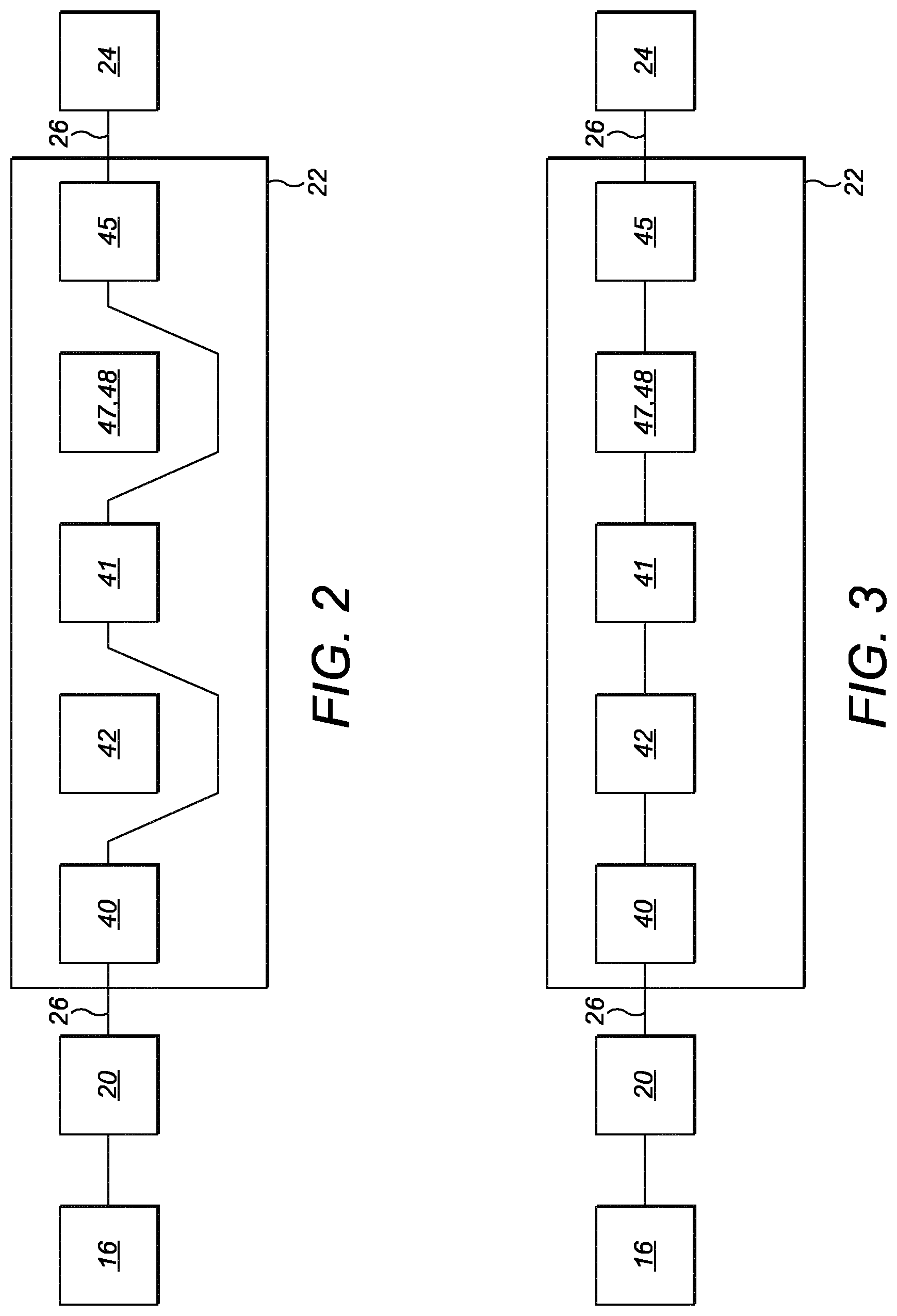
[0019] FIG. 2 is a schematic representation of components and a force path of the injection device of FIG. 1, with the dose limiting features disengaged;
[0020] FIG. 3 is a schematic representation of components and a force path of the injection device of FIG. 1, with the dose limiting features engaged;
[0021] FIG. 4 is a perspective view of another embodiment of the injection device;
[0022] FIG. 5 is an exploded view of the injection device of FIG. 4;
[0023] FIG. 5A is a perspective view showing further detail of the dose limit nut;
[0024] FIG. 5B is a perspective view showing further detail of part of the plunger rack;
[0025] FIG. 6 is a cross-sectional view of the injection device of FIG. 4;
[0026] FIGS. 7 and 7A-7C illustrate incrementing the dose;
[0027] FIGS. 8, 8A and 8B illustrate decrementing the dose;
[0028] FIGS. 9, and 9A-9D illustrate maximum/minimum dose limiting;
[0029] FIGS. 10 and 10a illustrate over-torque protection;
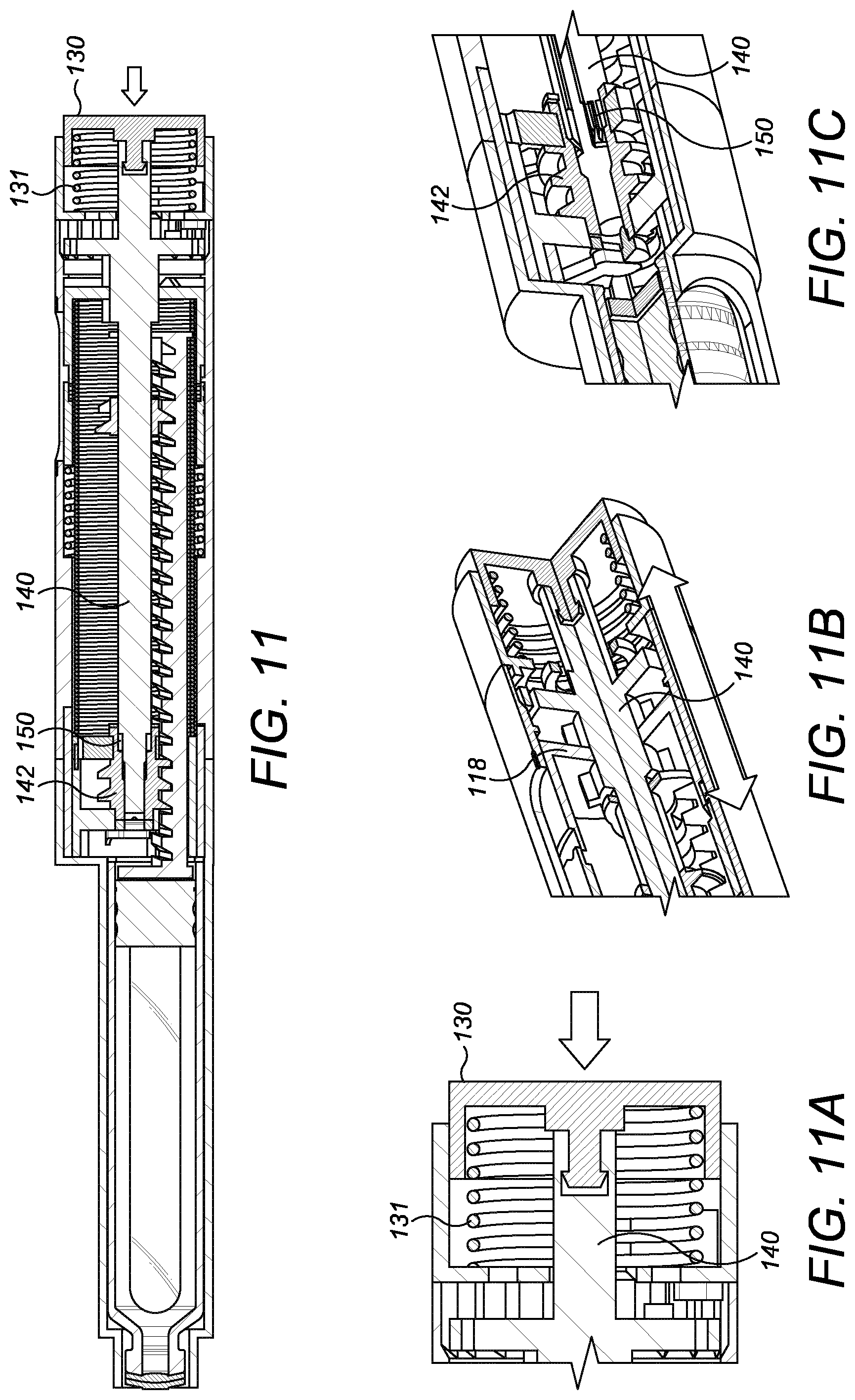
[0030] FIGS. 11 ,11A-11C, 12 and 12A-12B illustrate dose delivery;
[0031] FIGS. 13, 13A and 13B illustrate a haptic feedback feature;
[0032] FIGS. 14 and 14A-14E illustrate last dose protection;
[0033] FIG. 15 is a diagrammatic summary of the key engagement points of the components of the injection device of FIG. 4, at four stages of dose delivery;
[0034] FIG. 16 summarises schematically the mechanical motion of the drive shaft 140, dose limit nut 141, worm gear 142 and plunger rack 145 during dose setting (incrementing the dose);
[0035] FIG. 17 summarises schematically the mechanical motion of the drive shaft 140, dose limit nut 141, worm gear 142 and plunger rack 145 during dose delivery;
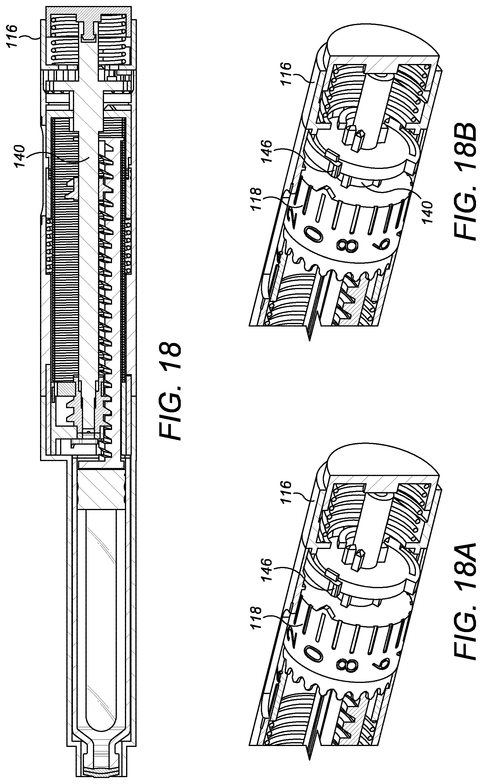
[0036] FIGS. 18, 18A and 18B show how the units wheel is incremented; and
[0037] FIGS. 19, 19A and 19B show how the tens wheel is incremented.
DETAILED DESCRIPTION
[0038] In the present disclosure, the following terms may be understood in view of the below explanations:
[0039] The term "injection device" may refer to a device intended for the injection of a medicament to the body and includes devices configured for various delivery methods, such as intradermal, subcutaneous, intramuscular, intravenous, intraosseous, intraperitoneal, intrathecal, epidural, intracardiac, intraarticular, intracavernous, and intravitreal, which may include via a cannula, catheter or similar device. Injection device includes syringes of all types, devices that contain said syringes such as auto-injectors, pen-injectors, patch injectors and other similar devices.
[0040] The term "pen-injector" may include any device configured to deliver a dose of a medicament from a cartridge.
[0041] The term "user" may refer to a medical practitioner, end user or other user associated therewith.
[0042] The term "coupling" may refer to a connection between components (not necessarily a direct connection; there may be intermediate components therebetween) that enables a force to be transmitted between the components.
[0043] The term "a rotational coupling" may refer to a coupling which enables a rotational force to be transmitted between the components.
[0044] The term "operatively connectable" may refer to at least two individual components which are releasably connectable together in such a way that the individual components can work together, for example wherein rotation of one of the individual components effects rotation of all of the operatively connected components.
[0045] The term "dose selector" may refer to a component or components which, when actuated by a user, enable a dose of medicament to be selected.
[0046] The term "dose indicator" may refer to a component or components which provide a display or indication to the user of the selected dose of medicament.
[0047] The term "splines" may refer to one or more ridges, ribs or other protrusions on one component which engage in corresponding grooves or the like on a second component to connect the two components together.
[0048] The term "a splined connection" may refer to a connection effected by one or more splines.
[0049] The term "forward" or "forwards" may refer to a direction towards the end of the injection device from which medicament is expelled.
[0050] The term "backward", "backwards", "rearwards" or "rearwardly" may refer to a direction away from the end of the injection device from which medicament is expelled.
[0051] The term "drive assembly" may refer to an assembly of components capable of using a driving force from, for example, a spring, to eject medicament from an injection device.
[0052] The term "backlash" may refer to a clearance caused by a gap between mechanical components.
[0053] The term "medicament" may include a substance in liquid or gas form. The medicament may be selected from the group comprising of: antipsychotic substances including risperidone, hormones, antitoxins, substances for the control of pain, immunosuppressives, substances for the control of thrombosis, substances for the control or elimination of infection, peptides, proteins, human insulin or a human insulin analogue or derivative, polysaccharide, DNA, RNA, enzymes, antibodies, oligonucleotide, antiallergics, antihistamines, anti-inflammatories, corticosteroids, disease modifying anti-rheumatic drugs, erythropoietin, or vaccines, for use in the treatment or prevention of rheumatoid arthritis, psoriatic arthritis, ankylosing spondylitis, ulcerative colitis, hormone deficiency, toxicity, pain, thrombosis, infection, diabetes mellitus, diabetic retinopathy, acute coronary syndrome, angina, myocardial infarction, atherosclerosis, cancer, macular degeneration, allergy, hay fever, inflammation, anaemia, or myelodysplasia, or in the expression of protective immunity.
[0054] When referring to the injection device, the term "containing the medicament" may refer to the medicament being contained within a suitable medicament container, such as a pre-filled syringe or cartridge, within the injection device.
[0055] The term "a force path" may refer to a path between two or more coupled components via which a force can be transmitted between the components. A force path may be "interrupted" if there is a gap between the two or more components, i.e. if they are no longer coupled. Transmission of force between coupled components may be "held back" for example by a ratchet arrangement, but in such a case the force path is not "interrupted".
[0056] The term "a clutch" may refer to a component or feature suitable for operatively connecting two component parts either by a positive fit e.g. with teeth, splines, grooves or the like suitable for engaging and disengaging each other, or by a non-positive (e.g. frictional) connection or a combination thereof. Disengaging the clutch may interrupt a force path between two or more coupled components.
Description of First Example Embodiment
[0057] An injection device 10 according to an embodiment of the present invention is shown in FIG. 1. The injection device 10 is configured to deliver a dose of medicament and extends along a longitudinal axis L between a front end 10a and a rear end 10b of the injection device 10. The injection device 10 has a housing 12 and a needle 14 projecting from the housing 12 at the front end 10a. A dose selector 16 is provided at the rear end 10b and is arranged to permit the selection of a desired dose of medicament for delivery through the needle 12 into an injection site. The dose selector 16 is capable of being rotated about the longitudinal axis L with respect to the housing 12 by a user to set the desired dose of medicament to be ejected from the injection device. The housing 12 includes an aperture 12a through which a dose indicator 18 is visible.
[0058] FIG. 2 shows a schematic representation of a force path 26 within the injection device 10. The internal components include the dose selector 16, a spring 20, a drive assembly 22 and a medicament container 24. The drive assembly 22 includes a drive shaft 40, a last dose rotary endstop 42, a dose limit nut 41, dose limiting endstops 47, 48 and a plunger element 45. The spring 20 is configured to provide a drive force to the drive assembly 22 such that the drive assembly 22 may act to dispense medicament from the medicament container 24.
[0059] The dose selector 16 is coupled to the spring 20 such that a charging force can be transmitted via the force path 26 from the dose selector 16 to the spring 20 in order to charge the spring 20. The spring 20 is charged when a force is applied to the spring 20 so as to elastically deform the spring 20, and the resulting elastic energy is stored by the spring 20 (i.e. it is prevented from elastically relaxing during a storage phase). Therefore, charging the spring 20 involves increasing the energy stored by the spring 20.
[0060] The spring 20 is coupled to the drive assembly 22 and is arranged to provide a driving force via the force path 26 thereto when energy stored by the spring 20 is released.
[0061] The spring is capable of storing energy necessary for ejecting the dose of medicament from the injection device.
[0062] The drive assembly 22 acts to expel medicament from the medicament container 24 using the plunger element 45 which is capable of providing an axial force for ejecting a dose of medicament from the container 24. In certain embodiments, the medicament container 24 may be a pre-filled syringe or cartridge having a barrel and a stopper moveable in the barrel. In such embodiments, the plunger element 45 may act to move the stopper so as to expel medicament through an opening in the barrel. In certain embodiments of the invention, the medicament cartridge may or may not be connected to a needle.
[0063] In embodiments where the spring 20 is a torsion spring, the spring 20 is charged by applying a torque to wind the spring 20 and elastic energy may be stored by the spring 20 and subsequently released as torque.
[0064] In embodiments where the spring 20 is a compression spring, the spring 20 may be charged by applying an axial force to compress the spring 20 and elastic energy may be stored by the spring 20 and subsequently released as an axial force.
[0065] The drive spring 20 when implemented as a torsion spring may be fixed at one end with respect to the housing 12 and rotationally coupled at its other end to the drive shaft 40 of the drive assembly 22.
[0066] In certain embodiments, the force path 26 may include one or more torque paths and/or one or more axial force paths, where one or more rotational to axial couplings are employed to switch between rotational and axial forces along the force path 26. Indeed, in certain embodiments, one or more intermediate components may be provided between any of the components shown in FIG. 2.
[0067] The drive shaft 40 and dose limit nut 41 are rotationally coupled together but are able to move axially with respect to one another. As shown in FIG. 2, as the drive shaft 40 is rotated, force is transmitted along the force path 26 to the dose limit nut 41 which therefore also rotates. The last dose rotary endstop 42 is not engaged (and is therefore not part of the force path 26) in FIG. 2.
[0068] The plunger element 45 is threaded so that the dose limit nut 41 is engaged with said plunger element 45 via said thread, in order to guide relative axial movement between the dose limit nut 41 and the plunger element 45. The dose limit nut 41 is provided with dose limiting endstop features 47, 48 which are capable of limiting axial travel of the dose limit nut 41 with respect to the plunger element 45, so as to limit maximum and minimum doses of medicament which can be set by the user. The dose limiting endstop features 47, 48 may engage with changes in the depth of the plunger element thread or formations on the thread, for example. The dose limiting endstop features 47, 48 are not engaged in FIG. 2 (and are therefore not part of the force path 26).
Maximum/Minimum Dose Limiting
[0069] As the drive shaft 40 is rotated during dose setting, the dose limit nut 41, which is rotationally coupled with the drive shaft 40, is also rotated. The dose limit nut 41 travels forwards along the plunger element thread when incrementing the dose and rearwards when decrementing the dose. When one of the dose limiting endstop features 47, 48 engages, the dose limit nut 41 cannot travel further in that axial direction. Axial travel of the dose limit nut 41 along the plunger element 45 during dose setting is only possible within a range determined by the dose limiting endstop features 47, 48. The dose limit nut 41 always remains within this range because, during dose delivery, the dose limit nut 41 does not move axially with respect to the plunger rack 45.
[0070] Limiting the travel of the dose limit nut 41 in this way sets the maximum and minimum doses of medicament that can be set during dose setting, for example 100 IU and 0 IU respectively.
[0071] FIG. 3 shows the condition in which one of the dose limiting endstops 47, 48 is engaged and is now part of the force path 26 between the dose limit nut 41 and the plunger element 45.
Last Dose Protection
[0072] When the medicament cartridge 24 is relatively empty, after several doses have already been delivered therefrom, it is undesirable for the user to be able to select a dose that is larger than the available quantity of medicament remaining. Last dose protection is provided to deal with this situation. Conveniently, the last dose protection is provided by the same component as the maximum/minimum dose limiting i.e. the dose limit nut 41.
[0073] During dose setting, if the user attempts to set a dose that is greater than the available injectable volume of medicament remaining in the container 24, the last dose rotary endstop feature 42 engages, as represented in FIG. 3. The last dose rotary endstop feature 42 prevents further attempted rotation of the dose limit nut 41 by the drive shaft 40 with which it is rotationally coupled. An over-torque feature (not illustrated) may be provided to offer an alternate or additional force path if the user continues to attempt to dial up the dose selector 16.
[0074] The dose limit nut 41 conveniently provides last dose protection and maximum/minimum dose limiting with a single component, reducing the total number of component parts required and simplifying the injection device's design.
Description of Second Example Embodiment
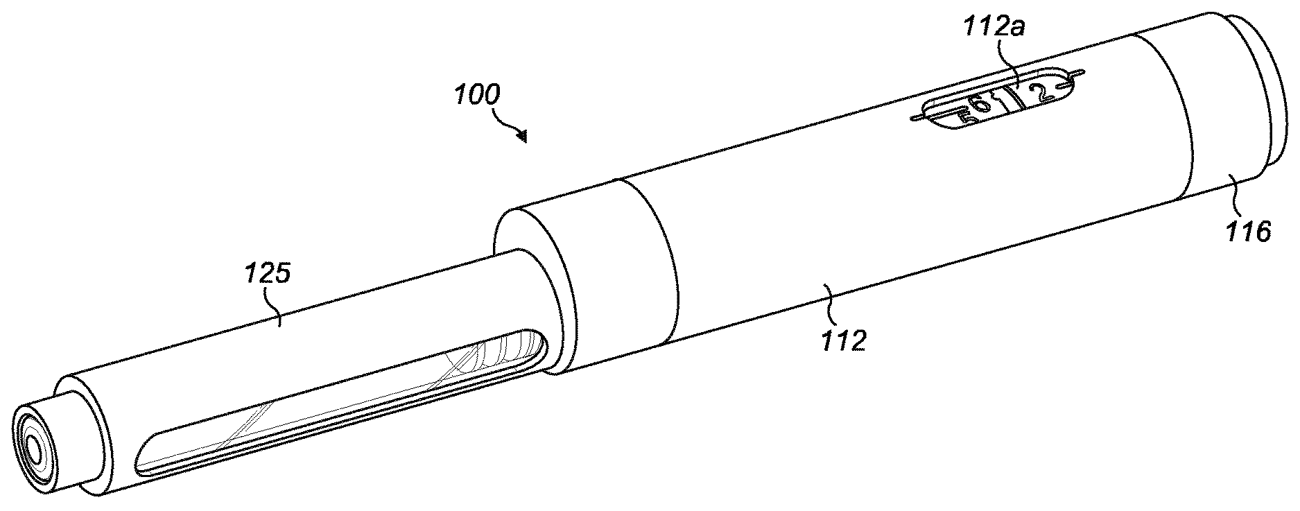
[0075] A further non-limiting embodiment of an injection device according to the present invention is illustrated in FIGS. 4-19B.
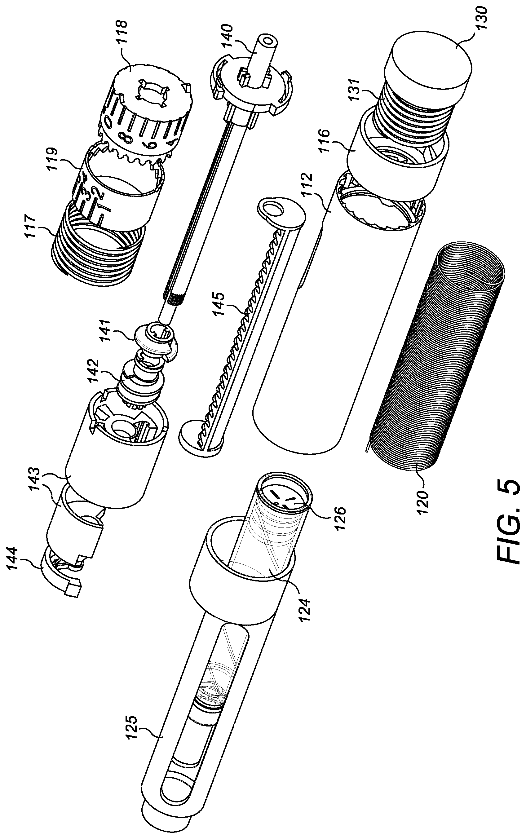
[0076] Referring to FIGS. 4-6, the injection device 100 includes a housing 112, a dose selector 116, a dose button 130 and dose button spring 131, a units wheel 118, a tens wheel 119, a dose indicator spring 117, a drive shaft 140, a drive spring 120, a dose limit nut 141, a worm gear 142, a worm gear support 143 and a worm gear rotational lock 144, all located concentrically about a common longitudinal axis L. The axis L extends between a front end 100a and a rear end 100b of the injection device 100.
[0077] The injection device 100 has a medicament cartridge 124 supported in a cartridge holder 125 at the front end 100a of the injection device 100. The cartridge 124 is sealed by an axially-moveable cartridge stopper 126 at its rear end. The cartridge and cartridge holder are located concentrically about a second longitudinal axis Lc, such that the cartridge is offset from the main housing 112, with L and Lc offset from one another as shown in FIG. 6.
[0078] The dose button 130 is biased rearwardly by the dose button spring 131. The dose selector 116 is provided at the rear end 100b of the injection device 100 and is arranged to permit the selection of a desired dose of medicament for delivery from the medicament cartridge 124 into an injection site. The dose selector 116 is axially constrained with respect to the housing 112 but is rotatable with respect thereto, about axis L. The dose selector 116 is rotationally coupled to the drive shaft 140 via pawl features 115, visible in FIG. 7A, which engage splines 149 on the drive shaft 140. The housing 112 is provided with teeth 113 (visible in FIG. 7B) on an inside surface thereof for engaging ratchet arms 146 on the drive shaft 140. Tabs 114 on the dose selector 116 are capable of depressing the drive shaft ratchet arms 146 when required, as shown in FIG. 8B. The housing 112 is also provided with ramp features 111 (visible in FIG. 12A) which facilitate disengagement of the ratchet arms 146 from the inside surface of the housing 112 when required.
[0079] A dose indicator is disposed within the housing 112 and displays reference indicia, such as numbers or symbols, to indicate the level of dose selected by the dose selector 116. The housing 112 includes an aperture 112a through which the dose indicator is visible. The dose indicator comprises the units wheel 118 for displaying units and the tens wheel 119 for displaying tens. The units wheel 118 is selectively engageable with the tens wheel to increment the tens wheel each time the units wheel moves through units 0 to 9. The units wheel 118 is rotationally coupled to the drive shaft 140.
[0080] As with the first embodiment, described with reference to FIGS. 1-3, biasing means in the form of dose indicator spring 117 biases the units wheel 118 and tens wheel 119 axially rearwardly in the housing.
[0081] The housing 112 has features on an inside surface thereof for engaging with the units wheel 118 and the tens wheel 119.
[0082] An internal surface of the housing 112 is provided with a tens housing feature 108 selectively engageable with the tens wheel 119 to prevent rotation thereof. The tens housing feature comprises one or more axially forwardly extending formations 108 which may be equally spaced around the internal circumference of the housing 112. The formations 108 engage with corresponding axially rearwardly extending formations 119b at the rear of the tens wheel 119. The tens housing feature formations 108 and the tens wheel formations 119b may be teeth, notches, castellations or any other shaped formations that, when engaged together, prevent relative rotation between the tens wheel 119 and the housing 112.
[0083] An internal surface of the housing 112 is provided with a units housing feature 107 capable of moving the units wheel axially-forward against said biasing means 117. The units housing feature is an axially forwardly extending formation 107 having a cam surface which can engage with an axially rearwardly extending formation 118b on the units wheel 118 in order to push the units wheel 118 axially forwards.
[0084] Teeth 118a on the front end of the units wheel 118 are engageable with correspondingly shaped teeth 119a at the rear end of the tens wheel 119. On the tens wheel 119, the teeth 119a (for engaging the units wheel) and the tens wheel formations 119b (for engaging the housing) may be concentrically arranged around the longitudinal axis of the injection device, with the teeth 119a radially inward of the formations 119b.
[0085] The drive spring 120 is a torsion spring which is fixed at one end with respect to the housing 112 and rotationally coupled at its other end to the drive shaft 140 via the units wheel 118.
[0086] A worm gear arrangement is provided which comprises a worm gear 142 meshed with a toothed plunger rack 145 located within the housing 112. During dose delivery, the worm gear 142 drives the plunger rack 145 forward which, in turn, pushes against the cartridge stopper 126 to deliver a dose of medicament. A splined clutch 150 at the forward end of the drive shaft 140 enables the worm gear 142 and drive shaft 140 to be splined together during dose delivery but not during dose setting, described in more detail later. In FIG. 6, the worm gear rotational lock 144 is engaged in the forward end of the worm gear 142, preventing rotation thereof. The worm gear rotational lock 144 is capable of being pushed axially forward by the drive shaft 140 in order to disengage the lock from the worm gear 142.
[0087] The dose limit nut 141 is keyed to the drive shaft 140 so that they are rotationally coupled but not axially coupled. The dose limit nut 141 is engaged with the teeth of the plunger rack 145 and can travel axially forward and backward along the plunger rack 145 as the dose is incremented or decremented respectively. The axial range within which the dose limit nut 141 can travel along the plunger rack 145 is determined by dose limit nut endstop features 141a, 141b which can engage features 147, 148 on the plunger rack thread to serve as endstops for the travel of the dose limit nut 141. FIG. 5A shows the maximum dose limit nut endstop feature 141a and the minimum dose limit nut endstop feature 141b in more detail. Endstops 141a, 141b are able to engage features 147, 148 respectively on the plunger rack 145 (FIG. 5B). These features 147, 148 are preferably changes in the depth of or formations on the plunger rack thread, past which the dose limit nut 141 cannot travel. During dose delivery, the dose limit nut 141 rotates about axis L with the drive shaft 140 to which it is keyed, but it does not move axially with respect to the plunger rack 145 with which it is engaged, thus always keeping the dose limit nut 141 within the range defined by the max/min dose endstops 141a, 141b.
[0088] The operation of the respective features of the injection device 100 will now be described in more detail below.
Dose Setting--Incrementing the Dose
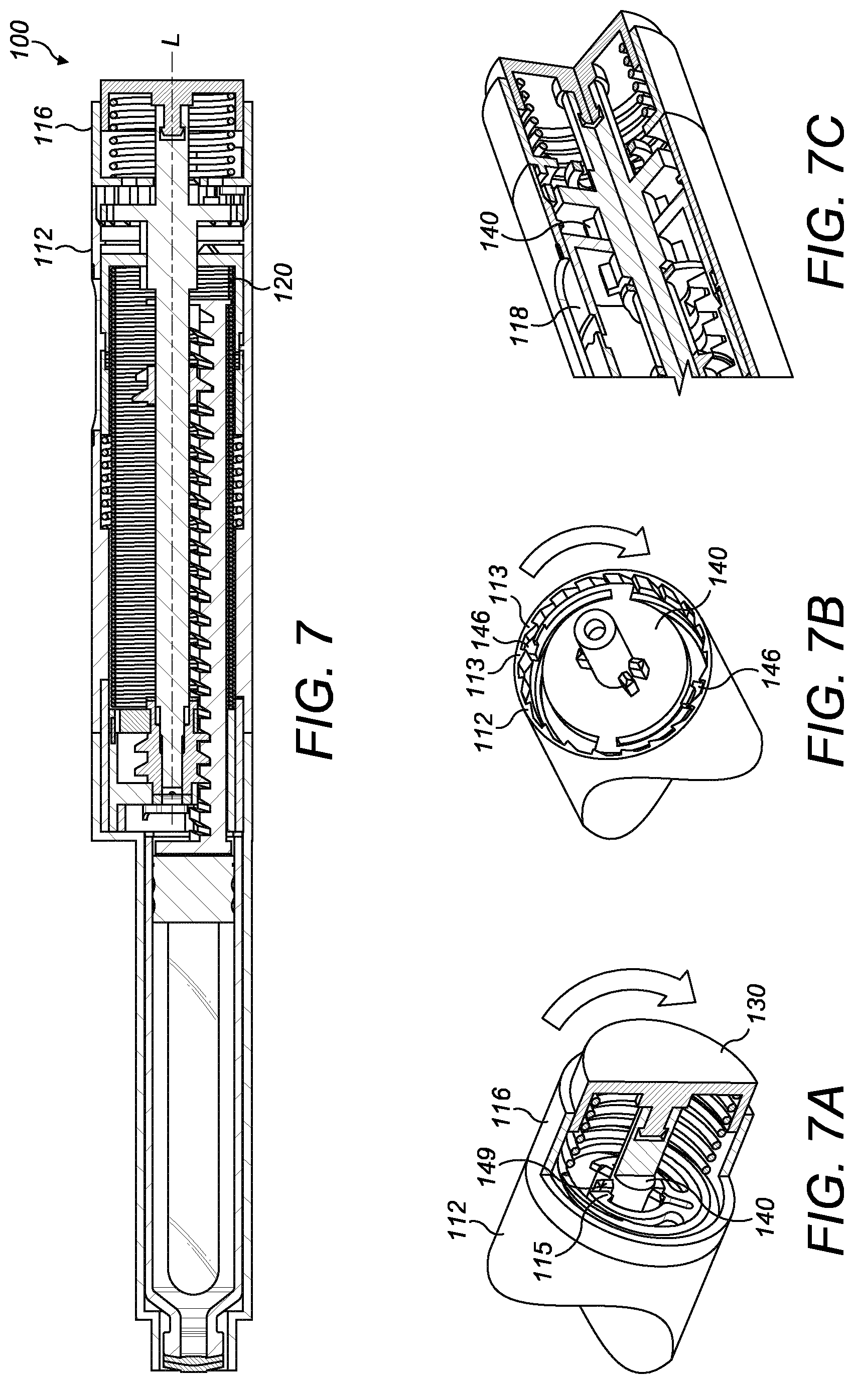
[0089] With the injection device 100 in the configuration shown in FIG. 7, the user grips the dose selector 116 and rotates it clockwise about axis L, with respect to the housing 112, in order to increment the dose and charge the drive spring 120. As the dose selector 116 is turned clockwise, the pawl features 115 engaging the splines 149 on the drive shaft 140 cause the drive shaft 140 to also be driven clockwise, as shown in FIG. 7A.
[0090] While the dose is being incremented, the ratchet arms 146 on the drive shaft 140 engage with the teeth 113 on the inside surface of the housing 112 to prevent un-winding by the drive spring 120, as shown in FIG. 7B.
[0091] As shown in FIG. 7C, the drive shaft 140 is splined to the units wheel 118 which charges or torques up the drive spring 120. In other words, torque is transferred from the dose selector 116 to the drive spring 120 directly through the dose indicator, i.e. the units wheel 118.
Dose Setting--Decrementing the Dose
[0092] When it is desired to decrement the selected dose, the dose selector 116 is turned anti-clockwise. As shown in FIG. 8A, as the dose selector 116 is turned anti-clockwise, there is a small amount of backlash at point A such that the dose selector 116 can rotate slightly with respect to the drive shaft 140. This small relative movement is sufficient to allow the tabs 114 on the dose selector 116 to depress the drive shaft ratchet arms 146 so that they can click past the housing teeth 113, allowing the drive spring to unwind slightly before the ratchet arms 146 catch again on the next housing tooth 113. This is represented in FIG. 8B. Each decrement preferably equates to 1 IU ("international unit") of medicament.
Dose Setting--Maximum/Minimum Dose
[0093] As the drive shaft 140 is rotated during dose setting, the dose limit nut 141, which is keyed to the drive shaft 140, is also rotated (FIG. 9A). The dose limit nut 141 travels forwards when incrementing the dose and rearwards when decrementing the dose (FIG. 9B). The dose limit nut 141 is engaged in the thread of the plunger rack 145. Endstop features 147, 148 are located on the plunger rack 145, past which the dose limit nut 141 cannot travel (FIG. 9C). These endstop features 147, 148 may be changes in the depth of the thread. As shown in FIG. 9D, when the dose limit nut 141 rotates into a position wherein the dose limit nut endstop feature 141a engages feature 147 on the plunger rack 145, further rotation of the dose limit nut 141 is prevented so that a dose of medicament greater than the desired maximum dose of medicament cannot be set. Limiting the travel of the dose limit nut 141 sets the maximum and minimum doses of medicament that can be set during dose setting, preferably 100 IU and 0 IU respectively.
Dose Setting--Over Torque
[0094] As shown in FIG. 10A, in the event the user applies too much force (over torque) to the dose selector 116 in either rotational direction, the dose selector pawl features 115 will flex radially outwardly to allow them to skip past splines 149 on the drive shaft 140. Preferably the interfacing surface areas of the pawl features 115 and/or splines 149 act as a cam lever, preferably having a matching angle and/or a defined static and dynamic surface friction at the interface surface. The over-torque for flexing out the dose pawl features 115 to skip past spline 149 is preferably at least 10% higher than the torque required for dialling up (incrementing) or dialling down (decrementing) the dose indicator 18, 118. The dialling up torque can be 30 to 80 Nmm, preferably less than 60 Nmm, more preferably 30 to 50 Nmm. The dialling down torque can be 20 to 60 Nmm, preferably less than 50 Nmm, more preferably 30 to 40 Nmm. The over-torque in the dialling up direction may be different to the over-torque in dialling down direction. The outward flexing force and/or strength of one flexible pawl arm 115 could be lower compared to a second flexible pawl arm.
[0095] FIG. 16 summarises schematically the mechanical motion of the drive shaft 140, dose limit nut 141, worm gear 142 and plunger rack 145 during dose setting (incrementing the dose). The drive shaft 140 rotates clockwise. The dose limit nut 141 rotates clockwise and advances forwards with respect to the plunger rack 145.
Dose Delivery
[0096] To initiate dose delivery, the user presses the dose button 130 against the bias of the dose button spring 131 as shown in FIG. 11A. This pushes the drive shaft 140 axially forwards. Although the drive shaft 140 is splined to the units wheel 118, it is free to slide axially with respect thereto (FIG. 11B).
[0097] As the drive shaft 140 advances, at its forward end, the splined clutch 150 between the drive shaft and the worm gear 142 engages (FIG. 11C, FIG. 15--Worm Gear Clutch 150). Preferably the drive element, in particular the worm gear 142 and the drive shaft 140 engage after 0.5 mm to 1.5 mm advancement of the dose button 130, more preferably after 0.8 mm to 1.2 mm advancement of the dose button 130. Once the clutch 150 has started to engage, the ratchet arms 146 on the drive shaft 140 begin to disengage from the inside surface of the housing 112 aided by ramp features 111 (FIG. 12A, FIG. 15--Hold Ratchet). Preferably the hold ratchet, in particular the ratchet arms 146 on the drive shaft 140 start to disengage from the structured, in particular toothed surface of the housing 112 after 1.5 mm to 2.5 mm advancement of the dose button 130, more preferably after 1.6 mm to 1.9 mm advancement of the dose button 130. Also, as the drive shaft 140 moves forward, the splines 149 coupling the drive shaft 140 to the dose selector 116 disengage (FIG. 12B, FIG. 15--Over torque ratchet). Preferably the over torque ratchet, in particular the drive shaft splines 149 on the drive shaft 140 start to disengage from the dose selector pawls 115 after 1.5 mm to 3.5 mm of advancement of the dose button 130, more preferably after 2 mm to 3 mm advancement of the dose button 130. The dose indicator and drive shaft 140 are now free to rotate about longitudinal axis L.
[0098] The drive spring 120 drives the units wheel 118 to rotate about longitudinal axis L. The units wheel 118 drives the drive shaft 140 which drives the worm gear 142.
[0099] FIG. 17 summarises schematically the mechanical motion of the drive shaft 140, dose limit nut 141, worm gear 142 and plunger rack 145 during dose delivery. The drive shaft 140, dose limit nut 141 and worm gear 142 all rotate anti-clockwise. Only the plunger rack 145 advances forwards. During dose delivery, the dose limit nut 141 rotates with the drive shaft 140 but does not move axially with the plunger rack 145. The dose limit nut 141 and the drive worm gear 142 preferably have the same thread pitch.
[0100] The worm gear 142 actuates the plunger rack 145 to move axially forwards causing the cartridge stopper 126 to be driven into the cartridge in order to expel medicament thus delivering the selected dose.
[0101] When the dose button 130 is released, the dose button spring 131 returns the dose button 130 and drive shaft 140 to their original starting positions. This axially rearward movement disengages the worm gear clutch 150 and re-engages the drive shaft ratchet arms 146 with the housing 112 thereby stopping dose delivery.
Dose Delivery--Haptic Feedback
[0102] During dose delivery, the drive shaft ratchet arms 146 run (rotationally) on a relatively smooth track 110 on the inside surface of the housing 112 (FIG. 13A). Optionally, this track could be modified to include ridges 109 which would provide audible/haptic feedback to the user during dose delivery (FIG. 13B). The ridges 109 are conveniently placed relatively close to the user's fingers.
Last Dose Protection
[0103] When the medicament cartridge 124 is relatively empty, after several doses have already been delivered therefrom, it is undesirable for the user to be able to select a dose that is larger than the available quantity of medicament remaining. Last dose protection is provided to deal with this situation. Conveniently, the last dose protection is provided by the same feature as the max/min dose limiting i.e. the dose limit nut 141.
[0104] As shown in FIG. 14, after several doses have been delivered, the plunger rack 145 and dose limit nut 141 have advanced axially forwards such that the dose limit nut 141 is approaching the worm gear 142. When there is less than a predetermined amount (e.g. 100 IU) of medicament available, the worm gear 142 serves as an endstop, stopping the dose limit nut 141 from moving further forwards and before the maximum dose limit feature 147 on the plunger rack 145 is reached (FIG. 14A). Preferably, it is the dose limit nut endstop feature for maximum dose limiting 141a which engages the worm gear 142. If the user tries to increment the dose further, torque is transmitted through the dose limit nut 141 into the worm gear 142, the torque being reacted to by the worm gear rotational lock 144 (FIG. 14B). As such, the worm gear 142 is unable to rotate due to rotational engagement with the rotational lock 144.
[0105] During dose delivery, when the drive shaft 140 is moved axially forwards, the worm gear clutch 150 is engaged before the worm gear rotational lock 144 is disengaged (FIG. 14C). The axially-forward movement of the drive shaft 140 causes its forward end to push the worm gear rotational lock 144 out of the front of the worm gear 142. With the worm gear rotational lock 144 disengaged, the worm gear 142 is free to rotate, driven by the drive shaft 140 (FIG. 14D). Once dose delivery is finished, the drive shaft 140 moves rearwardly. The worm gear rotational lock 144 re-engages, before the worm gear clutch 150 is disengaged (FIG. 14E).
[0106] FIG. 15 is a diagrammatic summary of the key engagement points of the injection device components, at four stages of dose delivery.
Dose Display
[0107] As already described above, during dose selection the user rotates the dose selector 116 which also drives the drive shaft 140 around. Ratchet arms 146 interact with teeth 113 in the housing 112 to prevent unwinding (FIG. 18A). The drive shaft 140 is splined to the units wheel 118 which, as it turns, increments the displayed unit (FIG. 18B).
[0108] The units wheel 118 and tens wheel 119 are biased rearwardly by dose indicator spring 117. Twice per revolution of the units wheel 118, the units wheel 118 is moved axially forwards by the cam surface of the units housing feature 107 engaging with the formation 118b on the units wheel 118. This axially forward movement causes the teeth 118a of the units wheel 118 to engage with the teeth 119a of the tens wheel 119 (FIG. 19A). Continued forward axial movement of the units wheel 118 pushes the formations 119b of the tens wheel 119 away from the tens housing feature 108, so that the tens wheel 119 is free to rotate with respect to the housing 112, allowing the tens wheel 119 to be driven around by the units wheel 118 by one increment (FIG. 19B).
[0109] In a preferred embodiment, the selectable and settable dose range is 1 to 100 IU, with a minimum dose setting of 1 IU, wherein per 360 degree rotation of the dose selector 116, 20 to 30 IU may be set. As the units wheel 118 and tens wheel 119 arrangement permits indication of the set IU dose by two digits, a much larger font size for the indicated dose number is usable, thus the arrangement affords better readability of the set dose and usability of the injection device 10, 100.
[0110] As with the first embodiment, described with reference to FIGS. 1-3, a dose limit nut 141 and a plunger element (plunger rack 145) are each threaded so that the dose limit nut 141 is engaged with said plunger element 145 via said thread, in order to guide relative axial movement between the dose limit nut 141 and the plunger element 145.
[0111] The thread is provided with dose limiting endstops 147, 148 which are capable of limiting axial travel of said dose limit nut 141 with respect to said plunger element 145, so as to limit maximum and minimum doses of medicament which can be set by the user.
[0112] The dose limit nut 141 is also engageable with a last dose rotary endstop (worm gear 142) which prevents further rotation of the dose limit nut 141 with respect to the drive shaft 140 so as to prevent the user setting a dose that is greater than an injectable volume of medicament remaining in said medicament container.
[0113] Throughout the description and claims of this specification, the words "comprise" and "contain" and variations of them mean "including but not limited to", and they are not intended to (and do not) exclude other moieties, additives, components, integers or steps. Throughout the description and claims of this specification, the singular encompasses the plural unless the context otherwise requires. In particular, where the indefinite article is used, the specification is to be understood as contemplating plurality as well as singularity, unless the context requires otherwise.
[0114] Features, integers, characteristics, compounds, chemical moieties or groups described in conjunction with a particular aspect, embodiment or example of the invention are to be understood to be applicable to any other aspect, embodiment or example described herein unless incompatible therewith. All of the features disclosed in this specification (including any accompanying claims, abstract and drawings), and/or all of the steps of any method or process so disclosed, may be combined in any combination, except combinations where at least some of such features and/or steps are mutually exclusive. The invention is not restricted to the details of any foregoing embodiments. The invention extends to any novel one, or any novel combination, of the features disclosed in this specification (including any accompanying claims, abstract and drawings), or to any novel one, or any novel combination, of the steps of any method or process so disclosed.
[0115] The reader's attention is directed to all papers and documents which are filed concurrently with or previous to this specification in connection with this application and which are open to public inspection with this specification, and the contents of all such papers and documents are incorporated herein by reference.
REFERENCE NUMERALS
[0116] 10 injection device
[0117] L longitudinal axis
[0118] 10a front end of the device
[0119] 10b rear end of the device
[0120] 12 housing
[0121] 14 needle
[0122] 16 dose selector
[0123] 18 dose indicator
[0124] 20 spring
[0125] 22 drive assembly
[0126] 24 medicament container
[0127] 26 force path
[0128] 40 drive shaft
[0129] 41 dose limit nut
[0130] 42 last dose rotary endstop feature
[0131] 45 plunger element
[0132] 47, 48 dose limit nut endstop features
[0133] 100 injection device
[0134] L longitudinal axis (housing)
[0135] Lc second longitudinal axis (cartridge)
[0136] 100a front end of the device
[0137] 100b rear end of the device
[0138] 107 units housing feature
[0139] 108 tens housing feature
[0140] 109 housing ridge features
[0141] 110 housing smooth inside surface track
[0142] 111 housing ramps for drive shaft ratchet arms
[0143] 112 housing
[0144] 112a aperture in the housing
[0145] 113 housing teeth
[0146] 114 tabs
[0147] 115 dose selector pawl
[0148] 116 dose selector
[0149] 117 dose indicator spring
[0150] 118 units wheel
[0151] 118a teeth on units wheel (for engaging tens wheel)
[0152] 118b formation on units wheel (for engaging units housing feature)
[0153] 119 tens wheel
[0154] 119a teeth on tens wheel (for engaging units wheel)
[0155] 119b formations on tens wheel (for engaging tens housing feature)
[0156] 120 drive spring
[0157] 124 medicament cartridge
[0158] 125 cartridge holder
[0159] 126 cartridge stopper
[0160] 130 dose button
[0161] 131 dose button spring
[0162] 140 drive shaft
[0163] 141 dose limit nut
[0164] 141a dose limit nut endstop feature for max dose limiting and last dose limiting
[0165] 141b dose limit nut endstop feature for min dose limiting
[0166] 142 worm gear
[0167] 143 worm gear support
[0168] 144 worm gear rotational lock
[0169] 145 plunger rack
[0170] 146 drive shaft ratchet arms
[0171] 147 max dose endstop on plunger rack for dose limit nut
[0172] 148 min dose endstop on plunger rack for dose limit nut
[0173] 149 drive shaft splines
[0174] 150 worm gear clutch
[0175] A backlash point for over-torque protection
* * * * *
D00000
D00001
D00002
D00003
D00004
D00005
D00006
D00007
D00008
D00009
D00010
D00011
D00012

D00013

D00014

D00015

D00016

D00017

D00018
D00019

XML
uspto.report is an independent third-party trademark research tool that is not affiliated, endorsed, or sponsored by the United States Patent and Trademark Office (USPTO) or any other governmental organization. The information provided by uspto.report is based on publicly available data at the time of writing and is intended for informational purposes only.
While we strive to provide accurate and up-to-date information, we do not guarantee the accuracy, completeness, reliability, or suitability of the information displayed on this site. The use of this site is at your own risk. Any reliance you place on such information is therefore strictly at your own risk.
All official trademark data, including owner information, should be verified by visiting the official USPTO website at www.uspto.gov. This site is not intended to replace professional legal advice and should not be used as a substitute for consulting with a legal professional who is knowledgeable about trademark law.