Methods For Patient-specific Shoulder Arthroplasty
Kehres; Clinton E. ; et al.
U.S. patent application number 16/541383 was filed with the patent office on 2019-12-05 for methods for patient-specific shoulder arthroplasty. The applicant listed for this patent is Biomet Manufacturing, LLC. Invention is credited to William Hartman, Clinton E. Kehres.
| Application Number | 20190365473 16/541383 |
| Document ID | / |
| Family ID | 47148967 |
| Filed Date | 2019-12-05 |


| United States Patent Application | 20190365473 |
| Kind Code | A1 |
| Kehres; Clinton E. ; et al. | December 5, 2019 |
METHODS FOR PATIENT-SPECIFIC SHOULDER ARTHROPLASTY
Abstract
A method of determining an optimal position of a glenoid implant. The method includes identifying a center point of a patient's glenoid fossa based on an image of the patient's glenoid fossa; determining the optimal position of the glenoid implant based on the location of the center point relative to a medial point of the patient's scapula; and selecting orientation of an alignment pin based on the determined optimal glenoid implant position such that the glenoid fossa will be prepared to receive the glenoid implant at the optimal position when the glenoid fossa is prepared with a cutting device or guide coupled to the alignment pin.
| Inventors: | Kehres; Clinton E.; (Warsaw, IN) ; Hartman; William; (Warsaw, IN) | ||||||||||
| Applicant: |
|
||||||||||
|---|---|---|---|---|---|---|---|---|---|---|---|
| Family ID: | 47148967 | ||||||||||
| Appl. No.: | 16/541383 | ||||||||||
| Filed: | August 15, 2019 |
Related U.S. Patent Documents
| Application Number | Filing Date | Patent Number | ||
|---|---|---|---|---|
| 15045431 | Feb 17, 2016 | 10426549 | ||
| 16541383 | ||||
| 13653893 | Oct 17, 2012 | 9301812 | ||
| 15045431 | ||||
| 61552079 | Oct 27, 2011 | |||
| Current U.S. Class: | 1/1 |
| Current CPC Class: | A61B 17/1684 20130101; A61B 17/1739 20130101; A61B 2034/108 20160201; A61B 17/1778 20161101; A61B 2034/102 20160201; A61F 2/4081 20130101; A61B 17/1703 20130101; A61B 34/10 20160201; A61B 2017/568 20130101 |
| International Class: | A61B 34/10 20060101 A61B034/10; A61B 17/17 20060101 A61B017/17 |
Claims
1-20. (canceled)
21. A method of guiding implantation of a glenoid implant at a desired implantation position in a patent's scapula comprising: providing software run with a processor to create a virtual three-dimensional model of a scapula created from one or more anatomical images of the patient's scapula, the software providing for: identifying a center point of a glenoid fossa; mapping a natural glenoid surface; visually displaying a line representing a natural inclination of the glenoid fossa on the virtual three-dimensional model; determining an anatomic version of the glenoid fossa; adjusting a desired anatomic version and inclination so as to customize a position of the glenoid implant; and designing an alignment pin guide, wherein the alignment pin guide is designed to guide the insertion of an alignment pin into the patient's scapula to achieve the desired implantation position for the glenoid implant.
22. The method of claim 21, further comprising selecting an orientation of a virtual alignment pin using the software and visually displaying the orientation of the virtual alignment pin on the virtual three-dimensional model at an angle from the desired implantation position.
23. The method of claim 22, wherein selecting an orientation of a virtual alignment pin includes identifying the center point of the glenoid fossa using three or more points at a rim of the glenoid fossa.
24. The method of claim 22, further comprising determining an inclination of the glenoid fossa by orienting the virtual alignment pin perpendicular to a second line that extends between the inferior rim of the glenoid fossa and the superior rim of the glenoid fossa, wherein the second line is visually displayed on the three-dimensional model.
25. The method of claim 22, further comprising inserting a surgical alignment pin into the patient's scapula, the surgical alignment pin positioned according to an orientation assigned virtually using the software and corresponding to the orientation assigned to the virtual alignment pin.
26. The method of claim 21, wherein identifying the center point of the glenoid fossa comprises selecting at least a first point on an anterior rim of the glenoid fossa and a second point on the posterior rim of the glenoid fossa.
27. The method of claim 26, further comprising determining a centerline of the glenoid fossa as a function of the first point on the anterior rim and the second point on the posterior rim.
28. The method of claim 27, further comprising displaying the centerline on the virtual model of the scapula.
29. The method of claim 26, further comprising positioning a virtual guide on the virtual model as a function of the first point on the anterior rim and the second point on the posterior rim
30. The method of claim 21, further comprising: identifying a superior rim of the glenoid fossa; identifying an inferior rim of the glenoid fossa; and orienting a virtual guide based on the identified superior rim and inferior rim.
31. A method of positioning a virtual guide on a virtual model of a patient's scapula for installing a glenoid implant, the method comprising: creating the virtual model of a patient's scapula using software run by a processor, the virtual model created from an anatomical image of the patient's scapula; identifying a center point of a glenoid fossa; mapping a natural glenoid surface; visually displaying a line representing a natural inclination of the glenoid fossa on the virtual three-dimensional model; determining an anatomic version of the glenoid fossa; adjusting a desired anatomic version and inclination so as to customize a position of the virtual guide; and positioning the virtual guide on the virtual model of the glenoid fossa as a time ion of the desired anatomic version and the inclination.
32. The method of claim 31, further comprising selecting an orientation of a virtual alignment pin using the software and visually displaying the orientation of the virtual alignment pin on the virtual three-dimensional model.
33. The method of claim 32, wherein selecting the orientation of the virtual alignment pin includes identifying the center point of the glenoid fossa using points at a rim of the glenoid fossa.
34. The method of claim 31, further comprising determining an inclination of the glenoid fossa by orienting the virtual alignment pin perpendicular to a second line that extends between the inferior rim of the glenoid fossa and the superior rim of the glenoid fossa, wherein the second line is visually displayed on the model.
35. The method of claim 31, further comprising virtually designing an alignment pin guide according to an orientation assigned virtually using the software and corresponding to the orientation assigned to the virtual alignment pin.
Description
CROSS-REFERENCE TO RELATED APPLICATIONS
[0001] This application claims the benefit of U.S. Provisional Application No. 61/552,079; filed on Oct. 27; 2011, the entire disclosure of which is incorporated herein by reference.
[0002] This application is related to the following concurrently filed United States patent applications; each of which is incorporated herein by reference: "Patient-Specific Glenoid Guides" (Atty. Doc. No. 5490-000950/US); "Patient-Specific Glenoid Guide" (Atty. Doc. No. 5490-000950/US/01); and "Patient-Specific Glenoid Guide and Implants" (Atty. Doc. No. 5490-000950/US/02).
FIELD
[0003] The present disclosure relates to methods for patient-specific shoulder arthroplasty.
BACKGROUND
[0004] This section provides background information related to the present disclosure, which is not necessarily prior art.
[0005] The shoulder joint is the third most replaced joint in the body. During surgery, a Steinman pin is often used as an instrument guide. The Steinman pin is placed in the scapula, and is precisely positioned to guide the reamer to prepare the joint for an implant that will recreate natural version/inclination in the joint, or any other desired version/inclination. The pin is typically positioned based on a visual assessment of the joint and the surgeon's experience. While orienting the pin in this manner is sufficient, a method and apparatus to facilitate placement of the pin and recreation of natural version and inclination, or any optimal version and inclination, would be desirable.
SUMMARY
[0006] This section provides a general summary of the disclosure, and is not a comprehensive disclosure of its full scope or all of its features.
[0007] The present teachings provide for a method of determining an optimal position of a glenoid implant. The method includes identifying a center point of a patient's glenoid fossa based on an image of the patient's glenoid fossa; determining the optimal position of the glenoid implant based on the location of the center point relative to a medial point of the patient's scapula; and selecting orientation of an alignment pin based on the determined optimal glenoid implant position such that the glenoid fossa will be prepared to receive the glenoid implant at the optimal position when the glenoid fossa is prepared with a cutting device or guide coupled to the alignment pin.
[0008] The present teachings also provide for a method of determining an optimal position of a glenoid implant. The method includes identifying a center point of the patient's glenoid fossa based an image of the patient's glenoid fossa; determining the optimal position of the glenoid implant based on a linear line extending between the center point and an area proximate to a most medial surface of the patient's scapula; and selecting orientation of an alignment pin based on the determined optimal glenoid implant position such that the glenoid fossa will be prepared to receive the glenoid implant at the optimal position when the glenoid fossa is prepared with a cutting device or guide coupled to the alignment pin.
[0009] The present teachings further provide for a device for optimally positioning a glenoid implant during repair of a patient's shoulder joint. The device includes a patient specific surface designed to be received within the patient's glenoid fossa. An alignment pin guide extends from a first opening defined by the patient specific surface. The alignment pin guide is positioned and angled to guide insertion of the alignment pin into the glenoid fossa such that the alignment pin passes through a center of the glenoid fossa towards a medial point of the patient's scapula, thereby orientating the alignment pin such that the glenoid fossa will be prepared to receive the glenoid implant at an optimal position when the glenoid fossa is prepared with a cutting device or guide coupled to the alignment pin. The device can be removed from cooperation from the patient's glenoid fossa without removing the alignment pin.
[0010] Further areas of applicability will become apparent from the description provided herein. The description and specific examples in this summary are intended for purposes of illustration only and are not intended to limit the scope of the present disclosure.
DRAWINGS
[0011] The drawings described herein are for illustrative purposes only of selected embodiments and not all possible implementations, and are not intended to limit the scope of the present disclosure.
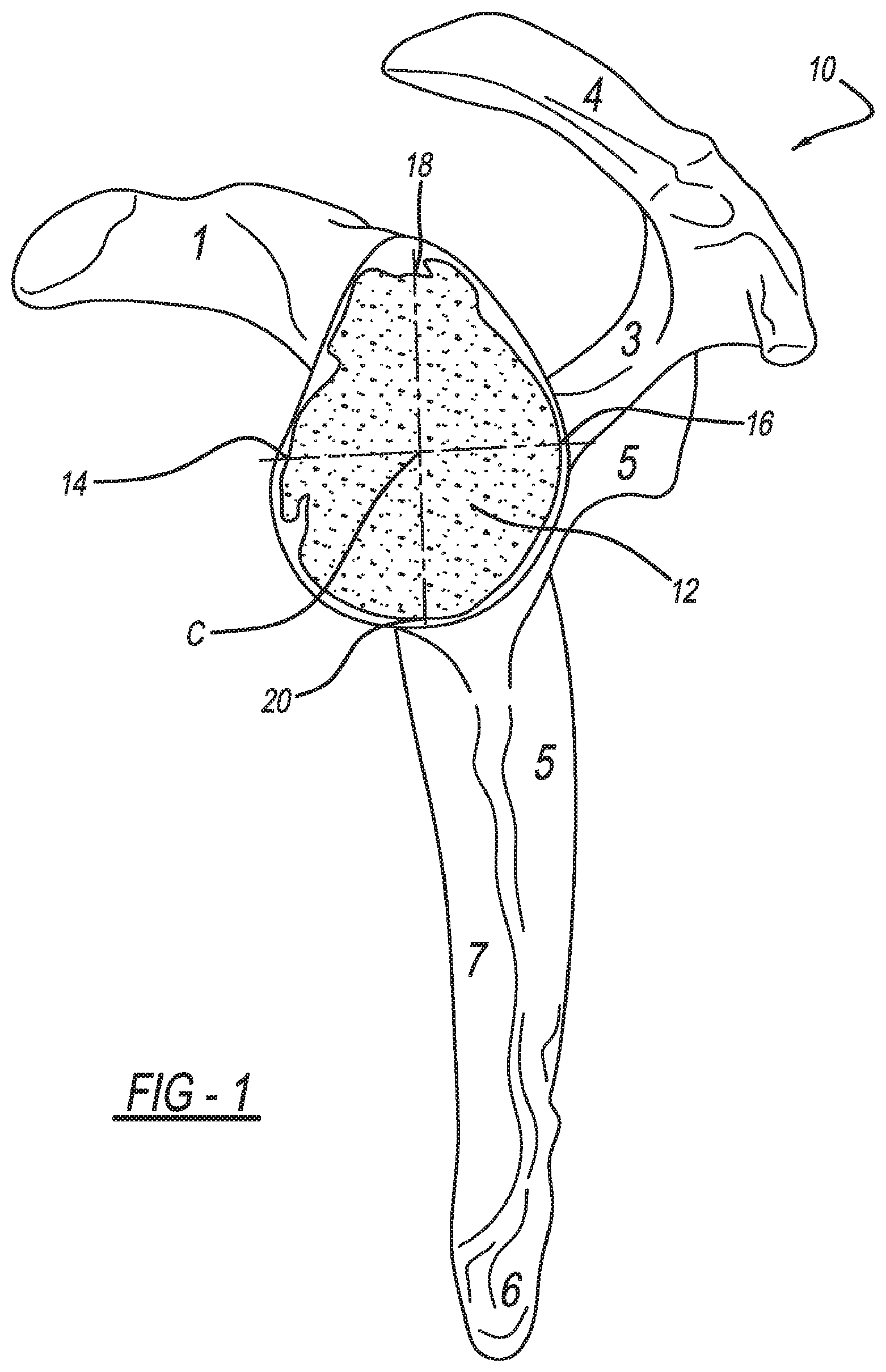
[0012] FIG. 1 is a lateral view of a scapula and a damaged glenoid fossa in need of repair, a center of the glenoid fossa is identified and used to identify optimal version and inclination in accordance with the present teachings;
[0013] FIG. 2A illustrates methods for achieving optimal glenoid version and inclination according to the present teachings;
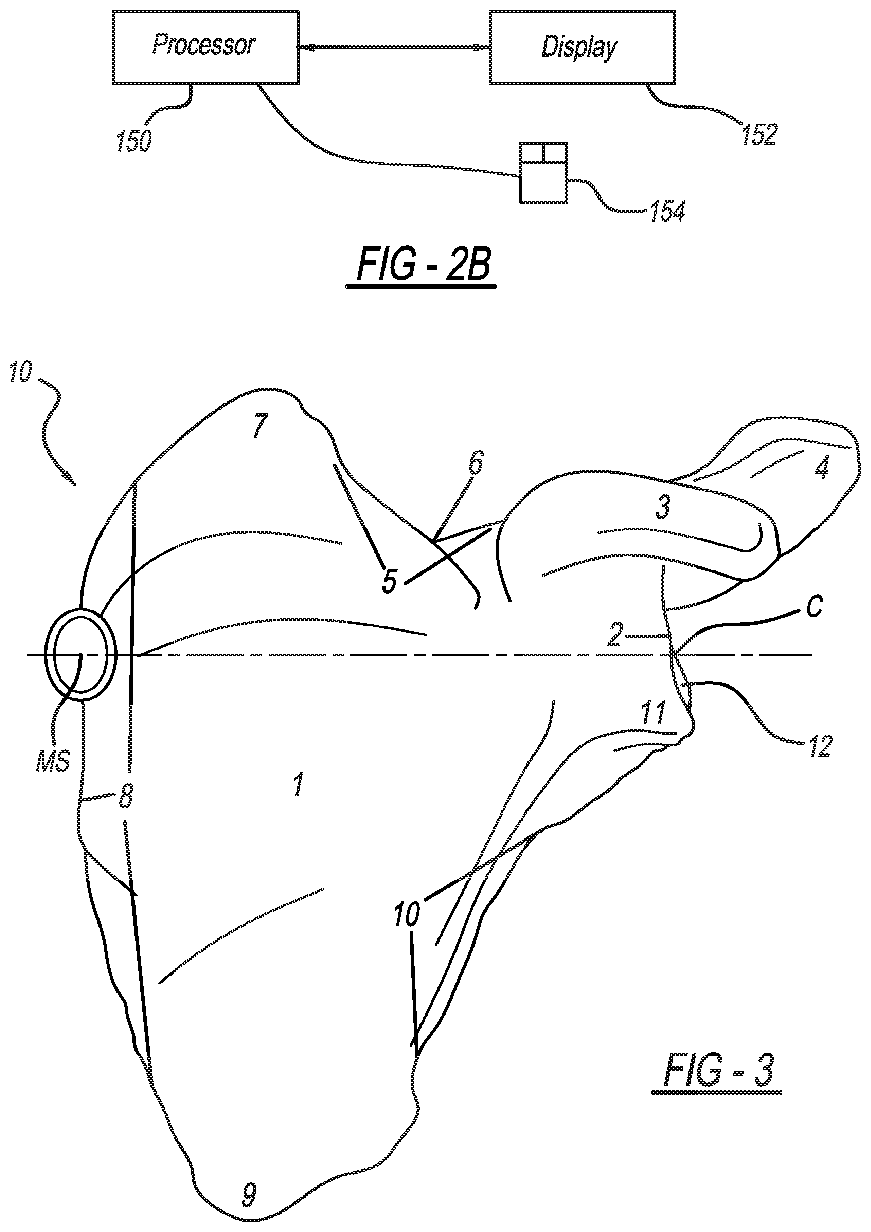
[0014] FIG. 2B illustrates a processor, display, and input device for performing methods according to the present teachings;
[0015] FIG. 3 illustrates providing optimal glenoid version and inclination based on the location of the center of the glenoid fossa relative to a most medial surface of the patient's scapula;
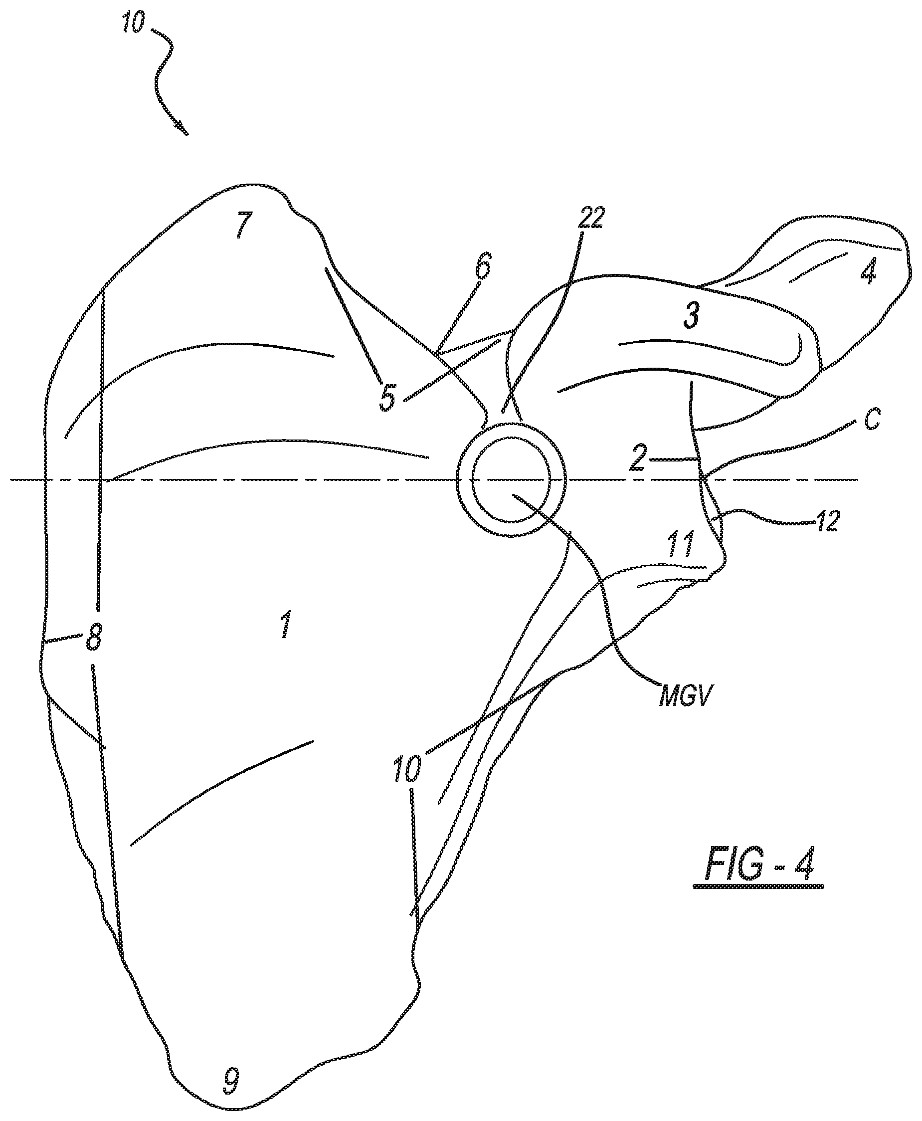
[0016] FIG. 4 illustrates providing optimal glenoid version and inclination based on the location of the center of the glenoid fossa relative to a most medial portion of the patient's medial glenoid fossa;
[0017] FIG. 5 illustrates use of a native glenoid face to provide optimal glenoid version and inclination; and
[0018] FIG. 6 is a perspective view of a patient specific alignment guide according to the present teachings coupled with a glenoid fossa.
[0019] Corresponding reference numerals indicate corresponding parts throughout the several views of the drawings.
DETAILED DESCRIPTION
[0020] Example embodiments will now be described more fully with reference to the accompanying drawings.
[0021] With initial reference to FIG. 1, a human scapula is illustrated at reference numeral 10. The scapula 10 includes a glenoid fossa 12. As illustrated, the glenoid fossa 12 is damaged, such as due to wear, and is in need of repair. To prepare the glenoid fossa 12 to receive an implant at predetermined, optimum version and inclination, which may include natural version and inclination, the present teachings identify and use anatomic landmarks and algorithms to design a patient specific alignment pin positioning guide, which is illustrated at reference number 50 of FIG. 6 and will be described further herein.
[0022] With additional reference to FIG. 2A, methods for orienting an alignment pin, such as a Steinman pin for aligning a reamer, in order to provide optimal glenoid version and inclination, are illustrated at reference numeral 110. With initial reference to block 112, the center of the glenoid fossa 12 is first identified. The center of the glenoid fossa 12 can be identified in any suitable manner.
[0023] For example, a three-dimensional (3D) model of the patient's scapula 10 can be created based on CT images of the patient. The CT images can be provided in the form of DICOM images, which typically include about 200 CT image "slices" of the patient's scapula 10. Any suitable software can be used to process the DICOM images to isolate the scapula 10 from surrounding bone or non-bony regions, such as "ORS Visual" segmentation software from Object Research Systems. The 3D model of the scapula 10 is then made from the images using any suitable software that can create a 3D model, such as "ORS Visual." The 3D model is then imported into any suitable CAD software, such as Siemens NX or Solidworks, for example. To identify the center C, any suitable software (such as Siemens NX or Solidworks) or manual measurements based on the 3D model can be used, as well as a combination of both.
[0024] For example, using the CAD software the center C or an approximation thereof can be identified with a best fit circle referenced off three equally spaced points at the rim of the glenoid fossa 12. The location of the center C can then be refined based on the location of each of the following parts of the glenoid fossa 12: the anterior rim 14, the posterior rim 16, the superior rim 18, and the inferior rim 20. These parts of the glenoid fossa 12 can be automatically identified using suitable software, or can be identified manually using the CAD software by selecting points on the glenoid fossa 12, such as with a mouse (reference no. 154 of FIG. 2B, which is further described herein). Once the center C of the glenoid fossa 12 is identified, the center C can be used to identify orientation of a Steinman pin that will facilitate preparation of the glenoid fossa 12 to receive an implant at a predetermined, optimal version and inclination, as described herein.
[0025] With reference to blocks 114-120 of FIG. 2A, the center C can be used to virtually orient the alignment pin using suitable software, such as the Siemens NX CAD software, in a variety of different ways. FIG. 2B illustrates a processor 150, which can run the CAD software and DICOM image processing software. A user can interact with and operate the software using display 152 and a suitable input device, such as mouse 154. With initial reference to block 114, a transverse plane (or line) that passes through both the center C of the glenoid fossa 12 and the most medial surface (MS) of the scapula 10 can be identified to represent the position of the alignment pin to provide version control, as illustrated in FIG. 3. The most medial surface (MS) can be identified using suitable software, such as the CAD software, or manually identified on the display 152 using the mouse 154. The plane can be identified manually and drawn on the CAD model using the mouse 154, or can be identified using suitable software.
[0026] Inclination control can be identified using the natural inclination of the glenoid, which can be defined by marking two points, either manually using the mouse 154 or automatically using the software. The first point can be on the superior rim 18 of the glenoid fossa 12, and the second point can be on the inferior rim 20 of the glenoid fossa 12. The alignment pin can be arranged such that it is perpendicular to a line connecting the inferior and superior points of the glenoid fossa 12, and extends along the line of FIG. 3, which extends through both the center C of the glenoid fossa 12 and the most medial surface (MS) of the scapula 10. The pin can also be oriented about 8.degree. inferior to the C-MS line, which is based on an average position of the general population, or at any other suitable angle. Inclination can also be determined by matching a best fit sphere to the glenoid surface and connecting the center of the best fit sphere to the center C of the glenoid fossa 12, which can be performed manually using the CAD software or automatically with the CAD software and the mouse 154 or other suitable software run by the processor 150.
[0027] With reference to block 116, version control can also be defined by connecting the center C of the glenoid fossa 12 to the most medial point of the glenoid fossa 22, which is identified in FIG. 4 at MGV, with a line representing the position of the alignment pin either automatically or manually using the CAD software and the mouse 154. Other than referencing the most medial point of the glenoid fossa, the alignment pin is virtually aligned in the same manner described above in the discussion of block 114.
[0028] With reference to block 118 and FIG. 5, the native, undamaged face of the glenoid fossa 12 (to the extent present) can be used to reconstruct anatomic version. If enough of the natural glenoid surface 30 is present, the surface can be mapped using the CAD software or other suitable software to create an axis normal to the surface that passes through the center point C of the glenoid fossa 12. A best fit sphere can be used to create the orientation of the native glenoid surface. This created plane axis can then be used as the pin axis to orient the alignment pins.
[0029] With further reference to block 120, the inner cortex of the scapula 10 can be referenced to orient the alignment pin. After the center C of the glenoid fossa 12 is identified, a plane can be drawn using the CAD software and the mouse 154 from the center C to an area midway between anterior and posterior cortices of the scapula 10. This will ensure that the alignment pin is placed directly in the center of the inner scapula cortex.
[0030] Once the alignment pin is virtually positioned on the display 152 as described at blocks 114-120, the surgeon or other suitably trained person can adjust the virtual position of the alignment pin on the display 152 as necessary at block 122 to customize version and inclination. For example, the alignment pin may be adjusted such that it does not extend directly through the most medial surface (MS) of the scapula 10, but is rather angled to meet patient-specific needs.
[0031] Once the desired orientation of the alignment pin has been virtually set on the display 152 using suitable software, a patient specific alignment guide (FIG. 6 at 50) is formed, and then seated within the patient's glenoid fossa 12 at block 122 of FIG. 2A. The alignment guide 50 includes a patient specific surface 52 that corresponds to, and is a negative of, the patient's glenoid fossa 12. Extending from the patient specific surface 52 are one or more alignment pin guides 54, such as a first alignment pin guide 54A and a second alignment pin guide 54B. Each of the guides 54A and 54B are sized and shaped to receive a first alignment pin 56A and a second alignment pin 56B respectively. At block 124, the first alignment pin 56A is inserted through the first alignment pin guide 54A to within the scapula 10 during a regular "non-reverse" procedure, and the second alignment pin 56B is inserted through the second alignment pin guide 54B to within the scapula 10 during a reverse procedure. The alignment pins 56A and 56B will be positioned according to the orientation assigned virtually using the software in order to provide natural version and inclination, or any other predetermined optimal version and inclination.
[0032] With additional reference to block 128, after he first alignment pin 56A or the second alignment pin 56B is set in the scapula 10, the alignment guide 50 is removed from the glenoid fossa 12. A suitable reamer is then coupled to the set alignment pin 56A or 56B, which will properly position the reamer to prepare the glenoid fossa 12 to receive an implant at block 130 positioned to provide the predetermined optimal version and inclination. At block 132, the implant is attached to the glenoid fossa 12.
[0033] The present teachings can also be adapted to a reverse shoulder procedure. With a reverse procedure, the alignment guide 50 may be provided with additional apertures surrounding the alignment pin guides 54A and 54B to receive fasteners for a reverse shoulder glenoid base plate. The base plate can be oriented to provide optimal version and inclination determined as set forth above. The inclination can be at an inferior tilt of about 10.degree. in addition to the 8.degree. inferior tilt identified above.
[0034] The foregoing description of the embodiments has been provided for purposes of illustration and description. It is not intended to be exhaustive or to limit the disclosure. Individual elements or features of a particular embodiment are generally not limited to that particular embodiment, but, where applicable, are interchangeable and can be used in a selected embodiment, even if not specifically shown or described. The same may also be varied in many ways. Such variations are not to be regarded as a departure from the disclosure, and all such modifications are intended to be included within the scope of the disclosure.
* * * * *
D00000
D00001
D00002
D00003
D00004
D00005
XML
uspto.report is an independent third-party trademark research tool that is not affiliated, endorsed, or sponsored by the United States Patent and Trademark Office (USPTO) or any other governmental organization. The information provided by uspto.report is based on publicly available data at the time of writing and is intended for informational purposes only.
While we strive to provide accurate and up-to-date information, we do not guarantee the accuracy, completeness, reliability, or suitability of the information displayed on this site. The use of this site is at your own risk. Any reliance you place on such information is therefore strictly at your own risk.
All official trademark data, including owner information, should be verified by visiting the official USPTO website at www.uspto.gov. This site is not intended to replace professional legal advice and should not be used as a substitute for consulting with a legal professional who is knowledgeable about trademark law.