Smoking Article And Associated Manufacturing Method
Ademe; Balager ; et al.
U.S. patent application number 16/543336 was filed with the patent office on 2019-12-05 for smoking article and associated manufacturing method. The applicant listed for this patent is R.J. Reynolds Tobacco Company. Invention is credited to Balager Ademe, Vernon Brent Barnes, Billy Tyrone Conner, Evon L. Crooks.
| Application Number | 20190364954 16/543336 |
| Document ID | / |
| Family ID | 52273506 |
| Filed Date | 2019-12-05 |


View All Diagrams
| United States Patent Application | 20190364954 |
| Kind Code | A1 |
| Ademe; Balager ; et al. | December 5, 2019 |
SMOKING ARTICLE AND ASSOCIATED MANUFACTURING METHOD
Abstract
A method and apparatus for forming a smoking article are provided and involve engaging a heat generation segment and a tobacco rod segment with the wrapping material in a longitudinally spaced-apart relation, the outer wrapping material having a heat-conductive strip engaged therewith, and the heat generation segment and/or the tobacco rod segment at least partially overlapping one end of the heat-conductive strip. Lateral ends of the wrapping material are wrapped at most partially about the heat generation and tobacco rod segments such that the heat generation and tobacco rod segments cooperate with the heat-conductive strip to define a longitudinally-extending cavity accessible between the respective lateral ends of the wrapping material and heat-conductive strip. Aerosol generation elements are deposited into the longitudinally-extending cavity (i.e., by gravity feed) between the lateral ends of the heat-conductive strip, and the cavity is closed by overlapping and sealing the lateral ends of the wrapping material.
| Inventors: | Ademe; Balager; (Winston-Salem, NC) ; Barnes; Vernon Brent; (Advance, NC) ; Conner; Billy Tyrone; (Clemmons, NC) ; Crooks; Evon L.; (Mocksville, NC) | ||||||||||
| Applicant: |
|
||||||||||
|---|---|---|---|---|---|---|---|---|---|---|---|
| Family ID: | 52273506 | ||||||||||
| Appl. No.: | 16/543336 | ||||||||||
| Filed: | August 16, 2019 |
Related U.S. Patent Documents
| Application Number | Filing Date | Patent Number | ||
|---|---|---|---|---|
| 14098137 | Dec 5, 2013 | |||
| 16543336 | ||||
| Current U.S. Class: | 1/1 |
| Current CPC Class: | A24C 5/10 20130101; A24F 47/006 20130101 |
| International Class: | A24C 5/10 20060101 A24C005/10 |
Claims
1. A method of forming an elongate smoking article, said method comprising: engaging a heat generation segment and a tobacco rod segment with an outer wrapping material in a longitudinally spaced-apart relation in relation to a length of the outer wrapping material, the outer wrapping material having a heat-conductive strip engaged therewith, the heat-conductive strip having longitudinally spaced-apart ends arranged in relation to the length of the outer wrapping material, and at least one of the heat generation segment and the tobacco rod segment at least partially overlapping one of the longitudinal ends of the heat-conductive strip; wrapping lateral ends of the outer wrapping material at most partially about the heat generation segment and the tobacco rod segment such that the heat generation segment and the tobacco rod segment cooperate with the heat-conductive strip to define a longitudinally-extending cavity accessible between the lateral ends of the outer wrapping material and lateral ends of the heat-conductive strip; depositing a plurality of aerosol generation elements into the longitudinally-extending cavity between the lateral ends of the heat-conductive strip; and closing the longitudinally-extending cavity by overlapping and sealing the lateral ends of the outer wrapping material.
2. The method according to claim 1, further comprising engaging the heat-conductive strip with the length of the outer wrapping material.
3. The method according to claim 2, wherein engaging the heat-conductive strip comprises engaging the heat-conductive strip with the outer wrapping material by applying a lamination adhesive therebetween.
4. The method according to claim 1, wherein engaging the heat generation segment and the tobacco rod segment comprises engaging the heat generation segment and the tobacco rod segment with the outer wrapping material such that only the heat generation segment at least partially overlaps one of the longitudinal ends of the heat-conductive strip.
5. The method according to claim 1, further comprising engaging a spacer element with the heat generation segment, such that the spacer element and the tobacco rod segment cooperate with the heat-conductive strip to define the longitudinally-extending cavity, the spacer element being one of heat-conductive and air permeable.
6. The method according to claim 1, wherein wrapping lateral ends of the outer wrapping material comprises wrapping lateral ends of the outer wrapping material at most partially about the heat generation segment and the tobacco rod segment such that the longitudinally-extending cavity extends vertically downward from an opening defined between the lateral ends of the heat-conductive strip.
7. The method according to claim 1, wherein depositing the plurality of aerosol generation elements comprises depositing the plurality of aerosol generation elements, selected from the group consisting of pellets, beads, discrete small units, carbon pieces, extruded carbon pieces, alumina beads, marumarized tobacco pieces, extruded or compressed cylindrical or spherical elements, milled tobacco lamina, fillers, flavors, visible aerosol forming materials, binders, ovoid elements, irregularly shaped elements, shredded pieces, flakes, elements including tobacco, elements including a visible aerosol-forming material, and combinations thereof, into the longitudinally-extending cavity.
8. The method according to claim 7, wherein depositing the plurality of aerosol generation elements comprises selecting a plurality of forms of the aerosol generation elements, and separately depositing each selected form of the aerosol generation elements into the cavity.
9. The method according to claim 7, wherein depositing the plurality of aerosol generation elements comprises selecting a plurality of forms of the aerosol generation elements, combining the selected forms of the aerosol generation elements to produce an aerosol generation element mixture, and depositing the mixture into the cavity.
10. The method according to claim 1, wherein depositing the plurality of aerosol generation elements comprises depositing the plurality of aerosol generation elements into the longitudinally-extending cavity, such that the cavity is at least about 65% filled with the aerosol generation elements.
11. The method according to claim 1, wherein closing the longitudinally-extending cavity comprises wrapping the lateral ends of the heat-conductive strip about the aerosol generation elements such that the lateral ends of the heat conductive strip abut each other.
12. The method according to claim 1, wherein closing the longitudinally-extending cavity comprises wrapping the lateral ends of the heat-conductive strip about the aerosol generation elements such that the lateral ends of the heat-conductive strip overlap.
13. The method according to claim 1, wherein closing the longitudinally-extending cavity comprises applying a seam-sealing adhesive between the overlapping lateral ends of the outer wrapping material for sealing the lateral ends of the outer wrapping material together.
14.-26. (canceled)
Description
BACKGROUND OF THE DISCLOSURE
Field of the Disclosure
[0001] The present disclosure relates to products made or derived from tobacco, or that otherwise incorporate tobacco, and that are intended for human consumption; and more particularly, to the assembly of components associated with the production of segmented-type smoking articles.
Disclosure of Related Art
[0002] Popular smoking articles, such as cigarettes, have a substantially cylindrical rod-shaped structure and include a charge, roll or column of smokable material, such as shredded tobacco (e.g., in cut filler form), surrounded by a paper wrapper, thereby forming a so-called "smokable rod," "tobacco rod" or "cigarette rod." Normally, a cigarette has a cylindrical filter element aligned in an end-to-end relationship with the tobacco rod. Preferably, a filter element comprises plasticized cellulose acetate tow circumscribed by a paper material known as "plug wrap." Preferably, the filter element is attached to one end of the tobacco rod using a circumscribing wrapping material known as "tipping paper." Examples of tipping materials are described, for example, in U.S. Pat. No. 7,789,089 to Dube et al., and in U.S. Pat. App. Publ. Nos. 2007/0215167 to Crooks et al., 2010/0108081 to Joyce et al., 2010/0108084 to Norman et al., and 2013/0167849 to Ademe et al.; and PCT Pat. App. Pub. No. 2013/160671 to Dittrich et al., each of which is incorporated by reference herein. It also has become desirable to perforate the tipping material and plug wrap, in order to provide dilution of drawn mainstream smoke with ambient air. A traditional type of cigarette is employed by a smoker by lighting one end thereof and burning the tobacco rod. The smoker then receives mainstream smoke into his/her mouth by drawing on the opposite end (e.g., the filter end or mouth end) of the cigarette. Descriptions of cigarettes and the various components thereof are set forth in Tobacco Production, Chemistry and Technology, Davis et al. (Eds.) (1999); which is incorporated herein by reference. Through the years, efforts have been made to improve upon the components, construction and performance of smoking articles. See, for example, the background art discussed in U.S. Pat. No. 7,753,056 to Borschke et al.; which is incorporated herein by reference.
[0003] Certain types of cigarettes that employ carbonaceous fuel elements have been commercially marketed under the brand names "Premier" and "Eclipse" by R. J. Reynolds Tobacco Company. See, for example, those types of cigarettes described in Chemical and Biological Studies on New Cigarette Prototypes that Heat Instead of Burn Tobacco, R. J. Reynolds Tobacco Company Monograph (1988) and Inhalation Toxicology, 12:5, p. 1-58 (2000). Additionally, a similar type of cigarette recently has been marketed in Japan by Japan Tobacco Inc. under the brand name "Steam Hot One." Furthermore, various types of smoking products incorporating carbonaceous fuel elements for heat generation and aerosol formation have been described in the patent literature. See, for example, the types of smoking products and associated components that are proposed, described and referenced in U.S. Pat. No. 4,793,365 to Sensabaugh et al.; U.S. Pat. No. 7,647,932 to Cantrell et al., and U.S. Pat. No. 7,836,897 to Borschke et al.; U.S. Pat. Pub. Nos. 2007/0215168 to Banerjee et al.; 2013/0019888 to Tsuruizumi et al.; 2013/0133675 to Shinozaki et al., 2013/0269720 to Stone et al.; and 2013/0146075 to Poget et al.; PCT Pat. App. Pub. Nos. WO 2012/0164077 to Gladden et al.; WO 2013/098380 to Raether et al.; WO 2013/098405 to Zuber et al.; WO 2013/098410 to Zuber et al.; WO 2013/104914 to Woodcock; WO 2013/120849 to Roudier et al., WO 2013/120854 to Mironov; WO 2013/162028 to Azegami et al.; and WO 2013/160112 to Saleem et al.; and European Pat. App. Nos. EP 1808087 to Baba et al. and EP 2550879 to Tsuruizumi et al.; which are incorporated herein by reference.
[0004] Various manners and methods for assembling smoking articles that possess a plurality of sequentially arranged segmented components have been proposed. See, for example, the various types of assembly techniques and methodologies set forth in U.S. Pat. No. 5,469,871 to Barnes et al. and U.S. Pat. No. 7,647,932 to Crooks et al.; and U.S. Pat. App. Pub. Nos. 2010/0186757 to Crooks et al.; 2012/0042885 to Stone et al., and 2012/0067360 to Conner et al.; which are incorporated herein by reference.
[0005] It would be highly desirable to provide smoking articles that demonstrate the ability to provide to a smoker many of the benefits and advantages of conventional cigarette smoking, without delivering considerable quantities of incomplete combustion and pyrolysis products. Additionally, it would also be highly desirable to provide an efficient and effective manner and method associated with the manufacture and assembly of those types of smoking articles that incorporate a plurality of sequentially arranged segmented components.
BRIEF SUMMARY OF THE DISCLOSURE
[0006] The above and other needs are met by aspects of the present disclosure which, in one aspect, provides a method of forming an elongate smoking article. Such a method comprises engaging a heat generation segment and a tobacco rod segment with an outer wrapping material in a longitudinally spaced-apart relation in relation to a length of the outer wrapping material, wherein the outer wrapping material has a heat-conductive strip engaged therewith, wherein the heat-conductive strip has longitudinally spaced-apart ends arranged in relation to the length of the outer wrapping material, and wherein at least one of the heat generation segment and the tobacco rod segment at least partially overlaps one of the longitudinal ends of the heat-conductive strip. Lateral ends of the outer wrapping material are wrapped at most partially about the heat generation segment and the tobacco rod segment such that the heat generation segment and the tobacco rod segment cooperate with the heat-conductive strip to define a longitudinally-extending cavity accessible between the lateral ends of the outer wrapping material and lateral ends of the heat-conductive strip. A plurality of aerosol generation elements is deposited into the longitudinally-extending cavity between the lateral ends of the heat-conductive strip, and the longitudinally-extending cavity is closed by overlapping and sealing the lateral ends of the outer wrapping material.
[0007] Another aspect of the present disclosure provides an apparatus for forming an elongate smoking article. Such an apparatus comprises an assembly arrangement configured to engage a heat generation segment and a tobacco rod segment with an outer wrapping material in a longitudinally spaced-apart relation in relation to a length of the outer wrapping material, wherein the outer wrapping material has a heat-conductive strip engaged therewith, wherein the heat-conductive strip has longitudinally spaced-apart ends arranged in relation to the length of the outer wrapping material, and wherein at least one of the heat generation segment and the tobacco rod segment at least partially overlaps one of the longitudinal ends of the heat-conductive strip. A wrapping arrangement is configured to wrap lateral ends of the outer wrapping material at most partially about the heat generation segment and the tobacco rod segment such that the heat generation segment and the tobacco rod segment cooperate with the heat-conductive strip to define a longitudinally-extending cavity accessible between the lateral ends of the outer wrapping material and lateral ends of the heat-conductive strip. A dispensing arrangement is configured to deposit a plurality of aerosol generation elements into the longitudinally-extending cavity between the lateral ends of the heat-conductive strip, and a sealing arrangement is configured to close the longitudinally-extending cavity by sealing the lateral ends of the outer wrapping material together.
[0008] In certain aspects, the present disclosure provides an elongate smoking article having a lighting end and an opposed mouth end. Such a smoking article comprises a mouth end segment or portion disposed at the mouth end, and a tobacco rod segment or portion disposed between the lighting end and the mouth end portion. An aerosol generation system is located as a segment disposed between the lighting end and the tobacco segment. The aerosol generation segment is longitudinally disposed from a heat generation portion or segment disposed at the lighting end; and those two segments are in a heat exchange relationship such that heat produced by combustion of components of the heat generation segment upon aerosol forming components of the aerosol generation segment results in the production of aerosol. The longitudinally extending outer surfaces of the heat generation, aerosol generation and tobacco rod segments are circumscribed by an outer wrapping material so as to provide a rod that is in turn attached to the mouth end segment. A layer of heat conductive material is disposed beneath the outer wrapping material so as to provide an outer internal surface of the aerosol generation segment. The heat conductive layer most preferably overlies the outer longitudinal surface of heat generation segment in the region thereof adjacent to the aerosol generation segment; and the heat conductive layer optionally can overlie the outer longitudinal surface of the tobacco rod segment in the region thereof adjacent the aerosol generation segment. The aerosol generation segment further incorporates a plurality of parts or pieces or elements (e.g., pellets or beads) incorporating materials that generate aerosols upon the action of and in response to heat produced by a burning fuel element of the heat generation segment.
[0009] Another aspect of the present disclosure provides a manner or method for producing an elongate smoking article. That is, preformed heat generation and tobacco rod segments are arranged over the inner surface of a web of outer wrapping material in predetermined locations along that web. Also positioned over a predetermined location of the inner surface of the outer wrapping material is a layer of heat conductive material. During wrapping of the various segments with the outer wrapping material so as to form a wrapped rod comprising those three segments, parts, elements, or pieces of materials incorporating aerosol forming substances are downwardly deposited into a cavity that defines the aerosol generation segment. That is, a predetermined amount of pellets or beads can be dropped in a cavity located between the heat generation and tobacco rod segments. Wrapping of the outer wrapping material then is completed so as to provide a wrapped rod incorporating three longitudinally aligned cylindrical segments. The aerosol generation region of the wrapped rod is comprised of a plurality of pellets or beads or other elements circumscribed by a layer of heat conductive material. The wrapped rod incorporating the three longitudinally aligned segments then is attached to a mouth end piece (e.g., a cylindrical filter element) so as to provide a finished filtered cigarette.
[0010] Further features and advantages of the present disclosure are set forth in more detail in the following description.
BRIEF DESCRIPTION OF THE DRAWINGS
[0011] Having thus described the disclosure in general terms, reference will now be made to the accompanying drawings, which are not necessarily drawn to scale, and wherein:
[0012] FIG. 1 schematically illustrates a longitudinal cross-sectional view of a representative smoking article, according to one aspect of the present disclosure;
[0013] FIG. 2 schematically illustrates an enlarged cross-sectional end view of an aerosol generation segment of a representative smoking article, taken along line 2-2 in FIG. 1, according to one aspect of the present disclosure;
[0014] FIG. 3 schematically illustrates a section of a continuous web or strip of wrapping material used to manufacture a series of two-up combined upstream rods, according to one aspect of the present disclosure;
[0015] FIG. 4 schematically illustrates a longitudinal cross-sectional view of a continuous rod comprised of a series of two-up combined upstream rods, according to one aspect of the present disclosure;
[0016] FIG. 5 schematically illustrates a two-up combined upstream rod, according to one aspect of the present disclosure;
[0017] FIG. 6 schematically illustrates a two-up combined filtered smoking article, according to one aspect of the present disclosure;
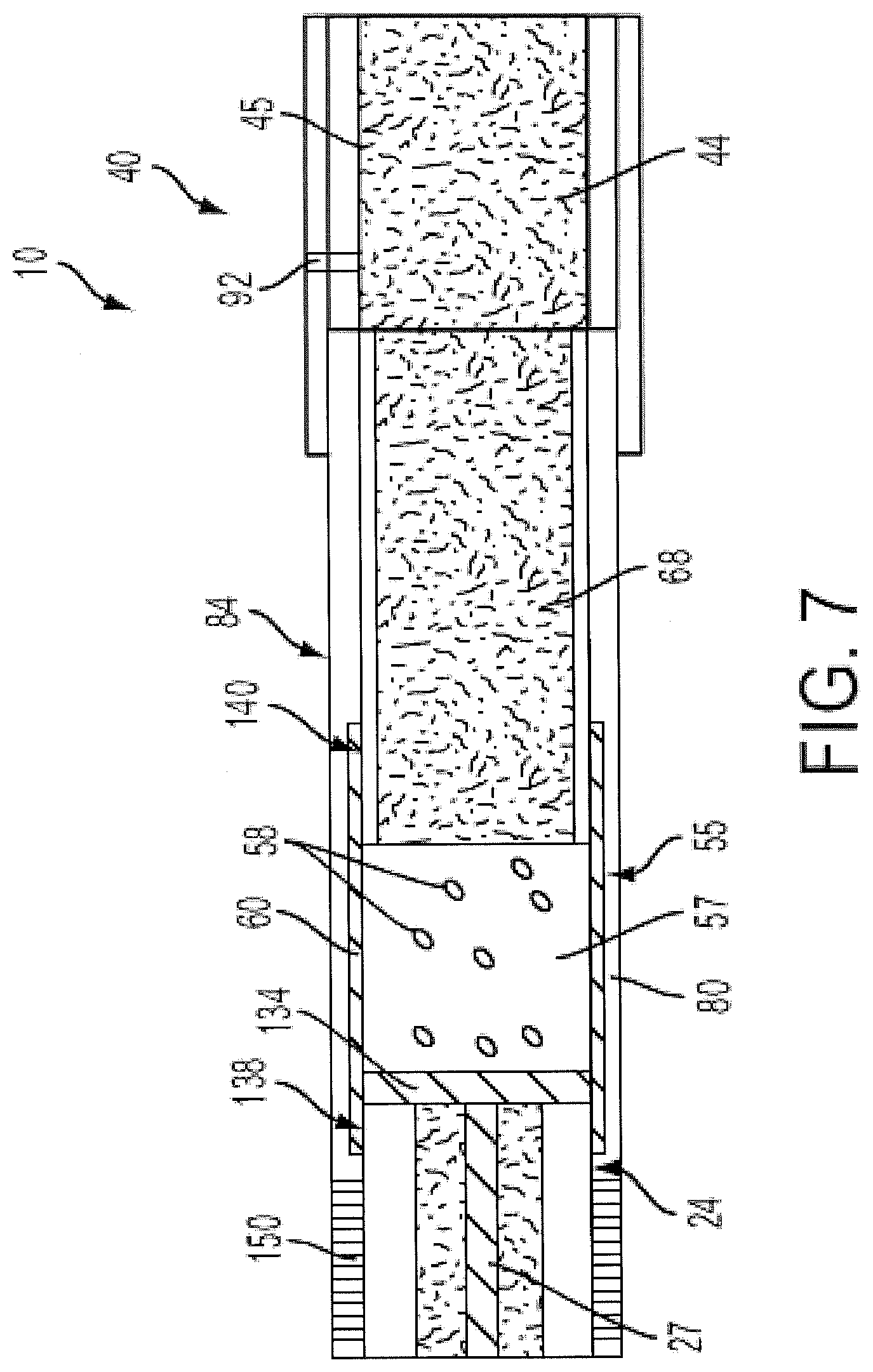
[0018] FIG. 7 schematically illustrates a longitudinal cross-sectional view of a representative smoking article, according to one aspect of the present disclosure;
[0019] FIG. 8 schematically illustrates a section of a continuous web or strip of wrapping material used to manufacture a series of two-up combined upstream rods;
[0020] FIG. 9 schematically illustrates a longitudinal cross-sectional view of a representative smoking article, according to one aspect of the present disclosure;
[0021] FIG. 10 schematically illustrates a longitudinal cross-sectional view of a continuous rod comprised of a series of two-up combined upstream rods, according to one aspect of the present disclosure;
[0022] FIG. 11 schematically illustrates a two-up combined filtered smoking article, according to one aspect of the present disclosure;
[0023] FIG. 12 schematically illustrates a longitudinal cross-sectional view of a representative smoking article, according to one aspect of the present disclosure;
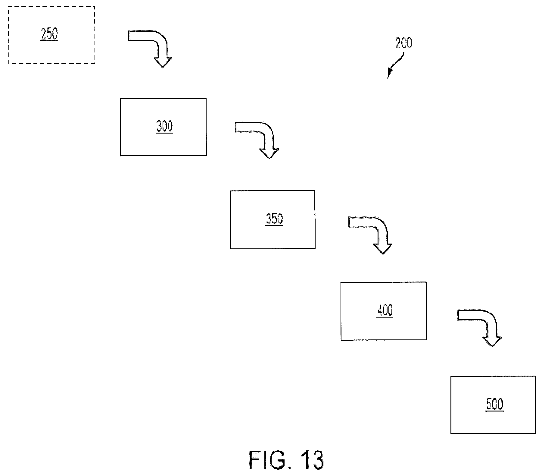
[0024] FIG. 13 schematically illustrates an apparatus for forming an elongate smoking article, according to one aspect of the present disclosure;
[0025] FIGS. 14 and 15 schematically illustrate alternate arrangements of a dispensing arrangement for depositing aerosol generation elements in a smoking article, according to aspects of the present disclosure; and
[0026] FIG. 16 schematically illustrates a method for forming an elongate smoking article, according to one aspect of the present disclosure.
DETAILED DESCRIPTION OF THE PREFERRED EMBODIMENTS
[0027] The present disclosure now will be described more fully hereinafter with reference to the accompanying drawings, in which some, but not all aspects of the disclosure are shown. Indeed, the disclosure may be embodied in many different forms and should not be construed as limited to the aspects set forth herein; rather, these aspects are provided so that this disclosure will satisfy applicable legal requirements. Like numbers refer to like elements throughout.
[0028] Referring to FIG. 1, there is shown a smoking article 10 in the form of a cigarette that is representative of the present invention. The smoking article 10 has a generally rod-like shape, and includes a lighting end 14 at one extreme end. Preferably, the smoking article 10 has the overall size, shape and general appearance of a filtered cigarette.
[0029] At the lighting end 14 is positioned a longitudinally-extending, generally cylindrical, heat generation segment 24. A typical heat generation segment 24 includes a heat source or fuel element 27 coaxially circumscribed by insulation 30, which is in turn coaxially encircled by wrapping material 35. The heat source 27 preferably is configured to be activated by direct ignition of the lighting end 14. That is, the heat source or fuel element is designed to be lit so as to burn and hence produce heat. Preferably, the fuel element incorporates a combustible carbonaceous material (e.g., a material that is comprised primarily of carbon); and most preferably, the fuel element is comprised primarily of carbonaceous material. Preferably, the insulation is provided in the form of a non-woven mat of glass filaments.
[0030] Preferably, the wrapping material 35 that circumscribes the insulation 30 is a paper wrapping material, such as, for example, the type of paper wrapping material used to as the circumscribing wrapping material of the insulation region of the heat source segment of the cigarette marketed under the trade name "Eclipse" by R. J. Reynolds Tobacco Company. Alternatively, that wrapping material 35 can be provided in the form of a tobacco-containing paper or reconstituted tobacco paper material, such as, for example, the type of tobacco-containing paper used as layer within the insulation region of the heat source segment of the cigarette marketed under the trade name "Eclipse" by R. J. Reynolds Tobacco Company, the gathered tobacco paper segment of the cigarette marketed under the trade name "Premier" by R. J. Reynolds Tobacco Company, or as set forth in U.S. Pat. No. 5,065,776 to Lawson et al. and U.S. Pat. No. 5,271,419 to Arzonico et al., which are incorporated herein by reference.
[0031] Preferably, each end of the heat generation segment 24 is open to expose the ends of each of the fuel element 27 and insulation 30. As such, drawn air can readily pass therethrough. The fuel element 27 and the surrounding insulation 30 can be configured so that the lengths of both are co-extensive (i.e., the ends of the insulation are flush with the respective ends of the fuel element, and particularly at the downstream end of the heat generation segment). Optionally, the insulation 30 may extend slightly beyond (e.g., from about 0.5 mm to about 2 mm beyond) either or both ends of the fuel element 27.
[0032] The cross-sectional shape and dimensions of the heat generation segment 24, prior to burning, can vary. Preferably, the cross-sectional area of the fuel element 27 makes up about 10 percent to about 35 percent, often about 15 percent to about 25 percent of the total cross-sectional area of that segment; while the cross-sectional area of the outer or circumscribing region (comprising the insulation 30 and relevant outer wrapping materials) makes up about 65 percent to about 90 percent, often about 75 percent to about 85 percent of the total cross-sectional area of that segment. For example, for a cylindrical smoking article 10 having a circumference of about 24 mm to about 26 mm, a representative fuel element 27 has a generally circular cross-sectional shape with an outer diameter of about 2.5 mm to about 5 mm, often about 3 mm to about 4.5 mm.
[0033] The smoking article 10 also possesses a mouth end 38 at the extreme end opposite the lighting end 14, and the mouth end 38 is considered to be downstream from the lighting end. At the mouth end 38 is located a filter segment 40. A typical filter segment 40 is comparable in many regards to that type of filter element traditionally used for the manufacture of cigarettes, and can be a single segment filter element or a multi-segment filter element. For purposes of illustration only, the filter segment 40 is a two piece segment that possesses an upstream piece 42 comprised of a cylindrical plug of filter material 44 (e.g., plasticized cellulose acetate tow) circumscribed by an outer plug wrap 45 (e.g., a paper plug wrap); and a downstream piece 47 comprised of a tubular filter plug 48 (e.g., a hardened tube of plasticized cellulose acetate tow). The filter pieces 42, 47 are combined to form the filter segment 40 using a plug wrap 49 that circumscribes the outer longitudinal surface of both pieces.
[0034] Located directly downstream from the heat generation segment 24 is an aerosol generation segment 55 comprised of a plurality of pellets or beads or other appropriate elements or combinations thereof 58 coaxially circumscribed by a generally tubular-shaped heat conductive member 60. The overall configuration of the aerosol generation segment 55 within the smoking article 10 can be considered to be generally cylindrical in nature. Representative preferred beads 58 are produced from a formulation that incorporates tobacco, components of tobacco and/or materials that are otherwise derived from tobacco. The beads 58 most preferably incorporate flavors and a visible aerosol forming material (e.g., glycerin or other material that generates a visible vapor that resembles smoke). That is, components of the beads 58 are preferably configured to act as substrate components for volatile flavors, vapor forming materials and aerosol forming materials that are carried thereby. In other aspects, some or all of the beads or pellets can be spherical capsules loaded into the aerosol generation segment may be heat sensitive so as to rupture when heated to release glycerin and tobacco flavor and/or nicotine. Also, in some aspects, the beads can be comprised of, for example, alumina, absorbent clay, silica, and/or absorbent carbon to hold and release an aerosol former.
[0035] The heat generation segment 24 and the aerosol generation segment 55 are considered to be physically separate from one another; and for the embodiment shown, those segments are positioned so that the downstream end of the heat generation segment abuts the upstream end of the aerosol generation segment (i.e., the back faces of the fuel element 27 and the circumscribing insulation 30). That is, heat generation segment 24 and the aerosol generation segment 55 are axially aligned in a serial end-to-end relationship, most preferably abutting one another. For example, it is highly preferred that some pellets 58, though physically separate and positioned downstream from heat generation segment 24, physically contact the downstream inner surface or face of the heat generation segment. Alternatively, those segments 24, 55 can be slightly spaced apart from one another so as each opposing end of each segment is not necessarily in physical contact with the other; and in such a circumstance an additional segment or spacer element acting as a spacer or screen (not shown, but see, e.g., element 134 in FIG. 7) positioned generally perpendicular to the longitudinal axis of the smoking article 10 can provide for physical separation of those two segments while maintaining a heat conductive relationship. That is, the spacer element 134 may preferably be heat-conductive and/or arranged to conduct heat from the heat generation segment 24 to the aerosol generation segment 55.
[0036] The longitudinally extending outer surface of the aerosol generation segment 55 is constructed from a layer of heat conductive material 60 (e.g., a layer or strip comprised of metal foil). That is, a representative aerosol generation segment 55 possesses a plurality of pellets and/or other appropriate elements 58 that are circumscribed along its length by a layer of strip of metal foil 60. A representative metal foil is, for example, aluminum foil having a thickness of about 0.01 mm to about 0.05 mm. Preferably, the metal foil 60 extends along the entire length of the outer co-axial surface of the aerosol generation segment 55; and it is also preferred that the metal foil extends over (i.e., at least partially overlaps) the outer co-axial surface 63 of the heat generation segment 24 (including the optional spacer element 134) in the region of the heat generation segment 24 adjacent to the aerosol generation segment 55.
[0037] Located directly downstream from the aerosol generation segment 55 (and directly upstream from the filter segment 40) is a tobacco segment 68, or other type of segment that acts to provide length and structure to the smoking article 10 while providing flavor or otherwise enhancing the sensory characteristics imparted by the smoking article during use. For the embodiment shown, the tobacco segment 68 is considered to be physically separate from the aerosol generation segment 55 as well as from the filter segment 40; and for the embodiments shown, those segments are positioned so that the downstream end of the aerosol generation segment abuts the upstream end of the tobacco segment, and the downstream end of the tobacco segment abuts the upstream end of the filter segment. A representative tobacco segment 68 possesses a charge or roll of tobacco filler 72 wrapped in a circumscribing paper wrapping material 76, and hence has the general form of a tobacco rod. In some aspects, up to about 10.5 mg menthol can be added to the tobacco in the tobacco rod or otherwise to the tobacco segment 68. However, in other aspects, it may be preferred to add any flavor or other sensory enhancement to the aerosol generation segment 55.
[0038] For the embodiment shown, each of the four segments (i.e., the heat generation segment 24, the aerosol generation segment 55, the tobacco rod segment 68 and the filter segment 40, as those segments are shown as respectively aligned in an abutting end-to-end relationship) are generally cylindrical in shape, and each of the segments is open at each end so that air can readily flow through those segments (i.e., air can enter the upstream end 14 and exit the downstream end 38).
[0039] The heat generation segment 24, aerosol generation segment 55 and tobacco segment 68 are serially positioned end-to-end, and are aligned so as to have the shape of a generally cylindrical rod possessing three physically separate, but generally abutting, cylindrical segments (and any additional cylindrical segment, for example, if an optional spacer element (not shown, but see, e.g., element 134 in FIG. 7) is implemented between the back face or downstream region of the heat generation segment and the front face or the upstream region of the aerosol generation segment). Those three upstream segments are in turn overwrapped over their respective outer coaxial surfaces with an outer wrapping material (i.e. a paper sheet) 80. As such, as a result of the combination of the three upstream segments, there is provided an upstream combined rod 84 (see, e.g., FIG. 9). Though not shown, at least a portion of the region of the outer wrapping material 80 that overlies the heat generation segment 24 can be perforated or otherwise provided in a form that renders that region relatively air permeable or highly porous to the transfer of air therethrough; and in such a manner, there is provided an enhanced source of atmospheric air for combustion of the fuel element.
[0040] The upstream combined rod 84 is physically connected to the filter segment 40. For the embodiment shown, a layer of tipping material 88 (e.g., tipping paper) circumscribes the outer peripheral surface of the filter segment 40 and an adjacent region of the outer wrapping material 80 (i.e., overlaps at least a portion of the combined rod 84) of the combined rod 84 (see, also, FIG. 12). Optional air dilution perforations 92 can be provided through selected regions of the tipping material 88, the underlying outer wrapping material 80 and the underlying wrapping material 76 of the tobacco rod 68. In some aspects, the air dilution perforations 92 may be configured, for example, so as to provide an air dilution of about 24%.
[0041] In use, the mouth end 38 of the smoking article 10 is inserted into the mouth of the smoker. The fuel element 27 located at lighting end 14 of the smoking article 10 is lit (e.g., using a cigarette lighter) so that the fuel element burns and hence produces heat. The fuel element 27 and the aerosol generation segment 55 are configured so as to be in a heat exchange relationship. That is, the heat generated by the combustion of the fuel element 27 acts to heat the beads or other elements 58 located in the aerosol generation segment 55 nearby or adjacent thereto. Additionally, heat resulting from the burning fuel element 27 is transferred to the heat conductive layer 60 that circumscribes the length of the aerosol generation segment 55; and, as such, the beads 58 located within the aerosol generation segment are heated. Upon draw on the mouth end 38 of the smoking article 10 by the smoker, air enters the lighting end 14 of the smoking article, is heated by the burning fuel element 27, and the hot air passing through the aerosol generation region 55 thereby heats the beads of that aerosol generation region. The drawn air also passes through the tobacco rod segment 68, and exits the filter element 40 into the mouth of the smoker. When smoked, flavored aerosol generated from the action of heat upon the components of the aerosol generation segment 55 and the components of the tobacco rod 68 are drawn into the mouth of the smoker. That is, the smoking article described with reference to FIG. 1 may be used in much the same manner as those cigarettes that have been commercially marketed under the trade names "Eclipse" by R. J. Reynolds Tobacco Company and "Steam Hot One" by Japan Tobacco Inc. As a result, when smoked, a highly preferred smoking article 10 yields flavored visible mainstream aerosol resulting principally from volatilized components of the aerosol generation segment 55 and of the tobacco rod segment 68, and that visible aerosol resembles in many regards the mainstream tobacco smoke of a traditional type of cigarette that burns tobacco cut filler.
[0042] Aerosols that are produced by the smoking article 10 are those that comprise air containing components such as vapors, gases, suspended particulates, and the like. Aerosol components can be generated from burning tobacco of some form (and optionally other components that are burned to generate heat, such as for example, when tobacco is incorporated within the fuel element 27 or as a component within the insulation 30 or circumscribing wrapper 35); by thermally decomposing tobacco caused by heating tobacco and charring tobacco (or otherwise causing tobacco to undergo some form of smolder, such as for example, when tobacco beads 58 in physical contact with the burning fuel element 27 are heated); and by vaporizing aerosol forming material. As such, the aerosol can contain volatilized components, combustion products (e.g., carbon dioxide and water), incomplete combustion products, and products of pyrolysis. Preferably, the levels of incomplete combustion products and products of pyrolysis within the aerosol are very low, as compared to the levels characteristic of tobacco products that yield smoke by burning tobacco cut filler. However, aerosol components most preferably are generated by the action of heat from the burning fuel element (and optionally other components that are burned to generate heat) upon substances that are located in a heat exchange relationship therewith. That is, aerosol is generated as a result of the action of the heat generation segment upon components of the aerosol generation segment. Preferably, components of the aerosol generation segment have an overall composition, and are positioned within the smoking article, such that those components do not have a tendency to undergo a significant degree of thermal decomposition (e.g., as a result of combustion, smoldering or pyrolysis) during conditions of normal use of the smoking article.
[0043] The overall dimensions of the smoking article 10, prior to being lit for use, can vary. Typically, a representative smoking article is a cylindrically shaped rod having a circumference of about 24 mm to about 27 mm; and an overall length of about 70 mm to about 120 mm, often about 80 mm to about 100 mm. A representative heat generation segment 24 typically has a length of up to about 30 mm, often up to about 20 mm, and frequently about 10 mm to about 15 mm. The aerosol generation segment 55 typically has a length of up to about 30 mm, often up to about 25 mm, and frequently about 10 mm to about 20 mm. Frequently, the lengths of each of the tobacco rod 68 and filter element 40 segments can vary as desired. For example, a representative tobacco rod segment 68 has an overall length of about 20 mm to about 50 mm, often about 30 mm to about 40 mm; and a representative filter segment 40 has a length of about 10 mm to about 35 mm, often about 20 mm to about 30 mm.
[0044] For purposes of example, a representative smoking article 10 has a length of about 83 mm and a circumference of about 25 mm. Such a cigarette 10 has a cylindrical heat generation segment 24 having a length of about 12 mm, a cylindrical aerosol generation segment 55 comprised of a plurality of beads 58 and having a length of about 13 mm, a tobacco rod segment 68 having a length of about 37 mm, and a filter segment 40 having a length of about 21 mm. The filter segment 40 is of a two piece construction having an upstream piece 42 comprised of a cylindrical plug of plasticized cellulose acetate tow having a length of about 10 mm, and a downstream piece 47 comprised of a steam bonded, plasticized cellulose acetate tube have having a length of about 11 mm. The upstream combined rod 84 of the cigarette is constructed using a 62 mm length of outer wrapping material 80 having a width of about 27 mm, and wrapped such that there is a lap seam of about 2 mm. A layer or patch of metal foil 60 having a thickness of about 0.04 mm, a length of about 17 mm and a width of about 25 mm extends over the length of aerosol generation segment 55 and about 4 mm of the length of the adjacent downstream region of the heat generation segment 24. The aerosol generating segment 55 has the form of a generally cylindrical hollow cavity 57 into which there is positioned a collection of about 120 to about 150 generally spherical beads 58 having a mean or nominal diameter of about 0.5 mm to about 2 mm (e.g., about 130 generally spherical beads of having an nominal diameter of 1.5 mm). For example, a plurality of beads 58 weighing about 300 mg to about 400 mg (preferably about 335 mg to about 350 mg) can be positioned within the cavity 57 that is designed to provide that aerosol generation segment. Preferably, sufficient beads are loaded into the aerosol generation segment cavity 57 to provide at least about 65 percent fill; in some instances, at least about 75 percent fill; in other instances, at least about 85 percent fill; and in some situations, at least about 95 percent of maximum fill, of that cavity with beads or other suitable elements 58. The filter segment 40 is attached to the upstream combined rod 84 using circumscribing standard tipping paper of 30 to 40 gsm that encircles the outer longitudinal surface of the filter segment and overlaps an adjacent 10 mm region of the outer wrapping material 80 that overlies the tobacco rod segment 68. A circumscribing ring of individual air dilution perforations 92 is positioned about 15 mm from the extreme mouth end 38 of the cigarette.
[0045] Referring to FIG. 2, there is shown an enlarged cross-sectional view of the aerosol generation segment 55 of a smoking article 10 of the type described previously with reference to line 2-2 in FIG. 1. That is, there is shown a preferred arrangement of the heat conductive metal foil or foil strip 60 that comprises the outer longitudinally extending surface of the aerosol generation segment 55 and outer wrapping material 80 that overlies that segment of the smoking article. A plurality of beads or other suitable elements 58 are located within the inner longitudinally-extending tubular cavity 57 defined by the arrangement of the metal foil 60. A representative foil has a thickness of about 0.02 mm. For the embodiment shown, the metal foil 60 is formed into a generally circular shape such that each laterally extending end abuts the other. For example, those lateral ends can abut one another (as shown in FIG. 2), nearly abut one another (so that a slight gap or space exits between those two lateral ends), one of the lateral ends can slightly overlap the other, or the lateral ends can otherwise be arranged to be aligned with each other. In some preferred instances, the lateral ends of the metal foil 60 may be arranged to meet in an abutting or nearly abutting relation, but the lateral ends need not necessarily be joined, welded, adhered, or otherwise secured to each other.
[0046] The laterally extending ends of the outer wrapping material (i.e., the elongate paper sheet) 80 are arranged so that one lateral end portion of the outer wrapping material overlaps the opposite lateral end portion, thereby forming a lap or overlap zone 95. A suitable adhesive material is applied in the region of overlap zone 98 so as to secure those lateral end portions together and hence secure the outer wrapping material in a generally tubular fashion around the heat conductive foil 60 of the heat generation segment 55. A representative lap seam adhesive material is provided as an adhesive formulation available as Code 2010-57 from Henkel Corporation. For purposes of example, a representative outer wrapping material is a paper wrapper comprised of wood pulp and calcium carbonate that is treated with sodium citrate and potassium citrate, has a basis weight of about 50 g/m.sup.2 and is available as Item I.D. 20008033 from Delfort Group Specialty Papers Inc. Additionally, for purposes of example, the metal foil 60 and outer wrapping material 80 are adhered or laminated together, typically using a coating of a suitable adhesive material (e.g., an adhesive formulation available as Code 32-220B from Henkel Corporation).
[0047] Referring to FIG. 3, there is shown a view of a portion of a continuous web of wrapping material or paper sheet 80 that is employed to provide the outer wrapper of a preferred upstream combined rod that is described previously with reference to FIG. 1 (see, also, FIG. 8). A representative continuous web 80, which can be provided as a tape-like strip off of a bobbin or other suitable source, has a width of about 27 mm; and as such, the web is designed so as to provide a cylindrical rod having a circumference of about 25 mm and an overlap seam of about 2 mm. Positioned at staggered but regular predetermined intervals along the web 80 are a series of patches or strips of a heat-conductive strip such as a metal foil 60. Each foil patch or strip 60 extends along the length of the web for a distance that roughly corresponds to the distance that the foil extends along the length of the aerosol generation segment, along at least a portion of the length of the heat generation segment, and in some instances, along at least a portion of the length of the tobacco rod segment (as the case may be). That is, the foil patch or strip 60 extends longitudinally along the wrapping material 80 for the length of the aerosol generation segment 55, and at least partially overlaps the heat generation segment 24. In some instances, the foil patch or strip 60 may also extend longitudinally to at least partially overlap the tobacco rod segment 68. If desired, though not shown, the regions of the web 80 that correspond to the regions of locations of the various heat generation segments can be perforated or otherwise rendered porous or permeable to enhanced air passage therethrough. A first distance of separation f between two adjacent foil patches or strips 60 corresponds to the product of the sum of the lengths of two heat generation segments minus twice the length that each heat generation segment is covered or overlapped by each respective foil patch or strip. Thus, for example, for a two-up heat generation segment having a length of 24 mm (i.e., two heat generation segments, each of 12 mm length), with the downstream end of each having a metal foil overlap of 4 mm, the distance f of separation of the two adjacent foil patches is 16 mm. A second distance of separation t between two adjacent foil patches corresponds to the sum of the lengths of two tobacco rod segments. Thus, for example, for a two-up tobacco rod segment having a length of 74 mm (i.e., two tobacco rods, each of 37 mm length), the distance t of separation of the two adjacent foil patches is 74 mm; and the spacing is accordingly reduced if a portion of the foil patch or strip covers or overlaps an adjacent region of the tobacco rod segment. Thus, the spacing of the adjacent patches or strips longitudinally along the continuous web is a staggered alternating pattern of f, t, f, t, f, t, and so on. As a result, metal foil strips or patches 60 are located on the continuous web 80 in a staggered, but regularly repeating pattern; and most preferably, the patches or strips of metal foil are positioned and aligned in a predetermined manner so that each patch aligns with the location of the corresponding aerosol generation segment of the smoking article. Additionally, representative foil patches each have widths of about 25 mm and are laterally positioned so as to not overlie the region of the web 80 intended to provide the overlap seam, as shown by distance s. Optical monitoring devices and/or other monitoring devices can be included in or with an assembly machine and incorporated into its operation to maintain accurate alignment/registration of the foil patches/strips with other smoking article components (e.g., the heating element/heat generation segment and the tobacco rod/tobacco rod segment) during assembly of smoking articles.
[0048] Referring to FIG. 4, there is shown a portion of a continuous rod 105 that is comprised of a series of two-up upstream combined rods 108. There is shown a continuous series of a two-up heat generation segment 110, an aerosol generation segment 55, a two-up tobacco rod segment 115 and an aerosol generating segment 55. In turn, each two-up heat generation segment 110 is cut in half perpendicular or laterally to its longitudinal axis, along line 5-5 as shown. As such, a continuing pattern of the intermediate two-up heat source segments 110 and intermediate two-up tobacco rod segments 115 is arranged on the continuous web of outer wrapping material 80 in relation to each aerosol generation segment 55, as defined by the metal foil patch or strip; and there also is provided a continuous web of outer wrapping material that possesses segments of such a metal foil 60 in spaced apart, pre-selected regions, longitudinally along the outer wrapping material 80, that each define the location of the aerosol generation segment 55.
[0049] The positioning of each foil strip or segment 60 on the continuous web or paper sheet is staggered in a pre-determined, patterned relationship. That is, for the embodiment shown, the distance separating one end of a foil segment 60 from the opposing end 60 of an adjacent foil segment is equal to the length of the two-up tobacco rod 115; while the distance separating the other end of that foil segment 60 from the other adjacent foil segment 60 is equal to the length of the two-up heat source segment 110 minus the overlap at each end of that segment 110. As such, for example, for a continuous web used for the manufacture of a series of continuous two-up rods, there is provided a continuous arrangement on that web of two-up tobacco rod, foil strip, two-up heat generation segment, foil strip, two-up tobacco rod, foil strip, two-up heat generation segment, foil strip, and so on.
[0050] The continuous web or elongate paper sheet 80 is formed so as to overwrap the various segments and to create a type of hollow longitudinally-extending cavity 57 in the region 120 defined by the location of the foil strip 60. That is, the outer wrapping material 80 may be at most partially wrapped about the heat generation and tobacco rod segments 24, 68 (i.e., to form an elongate "U" shaped channel), and therein forming one or more spaced-apart cavities defined through cooperation of adjacent heat generation and tobacco rod segments 24, 68 and the heat-conductive strip 60 disposed therebetween. Such partial wrapping may be provided, for example, by the assembly arrangement causing the outer wrapping material 80 to be urged against and partially into conformity with the respective perimeters of the heat generation and tobacco rod segments 24, 68 engaged therewith. Prior to providing complete overwrap of the continuous rod that is thereby formed, predetermined amounts of beads or other appropriate elements 58 are deposited into each cavity 57 defined by the cooperation of adjacent heat generation and tobacco rod segments 24, 68 and the heat-conductive strip 60 disposed therebetween. As such, upon sealing of the continuous rod 105, each completely manufactured aerosol generation segment 55 is formed.
[0051] Accordingly, such aspects of the present disclosure provide a method and apparatus for forming the disclosed smoking article which allow for the incorporation of a plurality of discrete aerosol generation elements into the smoking article, without necessarily requiring the plurality of aerosol generation elements to be in a cohesive form, or otherwise to be carried by a carrier member for maintaining the plurality of aerosol generation elements in a cohesive form, for delivery to and incorporation in the smoking article. However, one skilled in the art will appreciate that incorporating the plurality of aerosol generation elements, in a cohesive form with or without a carrier member, may be implemented as a further aspect of the present disclosure. Further, such aspects of the disclosed apparatus and method avoid the complexity associated with, for example, pre-forming a cylindrical member from the outer wrapping material, and then inserting the various components, including the discrete aerosol generation elements, longitudinally through an end of the cylindrical member for appropriate longitudinal positioning within the smoking article. Because the plurality of aerosol generation elements can be inserted directly into the cavity 57 disposed at an appropriate location along the length of the outer wrapping material, and be appropriately supported by the deliberately placed heat generation (and optional spacer element) and tobacco rod segments upon insertion, a higher speed manufacturing process may be realized (i.e., the smoking article can be manufactured "in-line," or in a single orientation (i.e., in a horizontal orientation), without changing the orientation thereof, for example, to introduce any of the components into the as-formed outer-wrapping material through one of the longitudinal ends thereof), along with greater efficiency, accuracy, and precision in placing the various other components of the smoking article, such as the heat-conductive strip/foil into engagement with the outer wrapping material. As such, significant cost savings may also be realized.
[0052] The manner by which a representative smoking article is manufactured can vary. The web or bobbin of wrapping material can be manufactured and supplied using known techniques. The various patches or strips of metal foil or appropriate heat-conducting strip also can be manufactured and supplied using known techniques. The foil patches or strips can be applied to predetermined locations on the continuous web of wrapping material using equipment such as that supplied by Montrade Srl and Strouse Corporation. The various segments of the upstream combined rod can be arranged at predetermined locations on the continuous web using equipment such as that available as Merlin from Hauni Maschinenbau AG and Combi from Montrade. Then the various cavities that are created along that continuous partially formed rod can be filled with pellets, beads, flakes, filler, or other appropriate elements, or combinations thereof. Filling of the various cavities with the materials that provide aerosol forming components can be accomplished using pneumatic dosing equipment, or other suitable means for providing a dropping or downward or gravity-facilitated filling of those cavities with the desired materials or appropriate elements. The partially sealed continuous rod so formed then is transferred to a rod forming unit (e.g., a type of device commonly used in the tobacco industry for production of a continuous filter rod) to seal the foil strip 60 and/or the continuous web 80 to form a continuous rod comprised of a repeating pattern of combined rods.
[0053] Referring to FIG. 5 (see, also, FIG. 10), there is shown a representative two-up upstream combined rod 108 that is provided by cutting the continuous rod shown in FIG. 4 at regular intervals through the center of each two-up heat generation segment (e.g., each two-up heat generation segment of the continuous rod is severed about its longitudinal center). Such a combined rod 108 is provided as a series of two-up upstream combined rods, each having a central two-up tobacco rod 115 and a heat generation segment 24 at each end (i.e., the inner segment of the two-up tobacco rod is configured as two intermediate segments jointed to one another as a common tobacco rod). Such a two-up upstream combined rod can facilitate handling during manufacturing of a smoking article. For example, a two-up rod can be processed using standard types of cigarette component processing and manufacturing equipment. In turn, each two-up upstream combined rod is cut in half perpendicular to its longitudinal axis (i.e., through the two-up tobacco rod at the location designed by line 5-5 in FIG. 5 and line 10-10 in FIG. 10) to provide two separate upstream combined rods.
[0054] Referring to FIG. 6 (see, also, FIG. 11), there is shown a representative two-up filtered cigarette 120 that is provided by positioning an upstream combined rod 84 at each end of a two-up filter segment 130. Each upstream combined rod is attached to each end of the two-up filter segment using tipping material to provide a two-up filtered cigarette (i.e., two intermediate cigarettes joined to one another by a common filter segment that has the configuration of two intermediate filter segments joined to one another). Subsequently, each two-up filtered cigarette is cut in half perpendicular to its longitudinal axis (i.e., through the two-up filter element in the location designated by line 6-6 in FIG. 6 and line 11-11 in FIG. 11) to provide two finished filtered cigarettes (see, e.g., FIG. 12).
[0055] Referring to FIG. 7, there is shown a smoking article 10 generally similar to that shown previously with reference to FIG. 1. The smoking article 10 possesses a heat conductive layer (i.e., foil strip 60) that that provides an outer coaxial surface of the aerosol generation segment 55. The heat conductive layer 60 also overlies an optional spacer segment 134 that is positioned between the heat generation segment 24 and the plurality of beads or other appropriate elements 58 of the aerosol generation segment 55. Typically, the spacer segment 134 is generally cylindrical in shape and of one piece construction, and is air permeable to allow the passage of drawn air through. Most preferably, the spacer segment 134 is heat conductive in nature, so that heat generated by the burning fuel element 27 can be readily conducted to the aerosol generation region 55. The length of the spacer segment can vary, and that segment typically extends about 5 mm to about 10 mm along the length of the upstream combined rod 84. Typically, the spacer segment 134 is comprised of a heat resistant material, such as a porous ceramic, a porous graphite material, a metal mesh or screen, a high temperature-resistant plastic or the like. In some instances, the spacer element 134 may include, for example, longitudinally-extending air passageways formed during design/manufacture, drilled therethrough, or otherwise molded, extruded, or shaped into the spacer element during manufacture thereof. If desired, the spacer segment 134 can incorporate catalytic materials, such as materials incorporating cerium or copper ions or oxides and/or salts of cerium and copper ions. See, for example, U.S. Pat. No. 8,469,035 to Banerjee et al. and U. S. Pat. Appl. Pub. Nos. 2007/0215168 to Banerjee et al., and 2011/0180082 to Banerjee et al.; which are incorporated herein by reference.
[0056] The heat conductive layer or foil strip 60 also circumscribes (and at least partially longitudinally overlaps) the outer longitudinally extending surface of the heat generation segment 24 in the region 138 thereof that is adjacent to the aerosol generation segment. The heat conductive layer 60 also circumscribes (and at least partially longitudinally overlaps) the outer longitudinally extending surface of the tobacco rod 68 in the region 140 thereof that is adjacent to the aerosol generation segment 55. For example, the heat conductive layer 60 can extend over or overlap about 2 mm to about 6 mm of the downstream longitudinal surface of the heat generation segment 24; and the heat conductive layer can extend over or overlap up to about 10 mm of the upstream longitudinal surface of the tobacco rod segment 68.
[0057] The filter element 40 is a one piece segment that is positioned at one end of the upstream combined rod 84 adjacent to one end of the tobacco rod segment 68, such that those segments are axially aligned in an end-to-end relationship, abutting one another and without any barrier therebetween. Preferably, the general cross-sectional shapes and dimensions of those aligned segments 24, 55, 134, 68 are essentially identical to one another when viewed on an end elevation perpendicularly to the longitudinal axis of the smoking article 10; and those segments are circumscribed by a layer of outer wrapping material 80. The region of the outer wrapping material 80 that overlies the heat generation segment 55 is provided with a series of perforations 150 (e.g., that region of the outer wrapping material is perforated with, for example, a series of electrostatic perforations, mechanically punched perforations or laser perforations) so as to provide a porous outer wrap around the heat generation region and hence allow for passage of air through the longitudinally extending region of the heat generation segment. The filter element possesses filter material 44 that is overwrapped along the longitudinally extending surface thereof with circumscribing plug wrap material 45. The cigarette can be air diluted by incorporation of a circumscribing ring of a plurality of perforations 92 through the tipping material 88 and the plug wrap 45 of the filter element. In one example, the filter material 44 includes plasticized cellulose acetate tow. Both ends of the filter element 40 are open to permit the passage of drawn air therethrough. Such a cigarette can be assembled by suitable modification of the materials and techniques described previously with reference to FIG. 3 through 6.
[0058] The components of the heat generation segment can vary. One component of the heat generation segment is the fuel element. Suitable heat generation segments and associated fuel elements thereof, and representative components, designs and configurations thereof, as well as manners and methods for producing those heat generation segments and the components thereof, are set forth in U.S. Pat. No. 4,714,082 to Banerjee et al.; U.S. Pat. No. 4,756,318 to Clearman et al.; U.S. Pat. No. 4,881,556 to Clearman et al.; U.S. Pat. No. 4,989,619 to Clearman et al.; U.S. Pat. No. 5,020,548 to Farrier et al.; U.S. Pat. No. 5,027,837 to Clearman et al.; U.S. Pat. No. 5,067,499 to Banerjee et al.; U.S. Pat. No. 5,076,297 to Farrier et al.; U.S. Pat. No. 5,099,861 to Clearman et al.; U.S. Pat. No. 5,105,831 to Banerjee et al.; U.S. Pat. No. 5,129,409 to White et al.; U.S. Pat. No. 5,148,821 to Best et al.; U.S. Pat. No. 5,156,170 to Clearman et al.; U.S. Pat. No. 5,178,167 to Riggs et al.; U.S. Pat. No. 5,211,684 to Shannon et al.; U.S. Pat. No. 5,247,947 to Clearman et al.; U.S. Pat. No. 5,345,955 to Clearman et al.; U.S. Pat. No. 5,469,871 to Barnes et al.; U.S. Pat. No. 5,551,451 to Riggs; U.S. Pat. No. 5,560,376 to Meiring et al.; U.S. Pat. No. 5,706,834 to Meiring et al.; U.S. Pat. No. 5,727,571 to Meiring et al.; U.S. Pat. No. 7,836,897 to Borschke et al.; U.S. Pat. No. 8,119,555 to Banerjee et al.; and U.S. Pat. No. 8,469,035 to Banerjee et al.; U.S. Pat. App. Pub. Nos. 2005/0274390 to Banerjee et al.; 2007/0215167 to Crooks et al.; and 2007/0215168 to Banerjee et al.; and U.S. patent application Ser. No. 13/448,835 to Stone et al. and Ser. No. 14/036,536 to Conner et al.; which are incorporated herein by reference. Other representative types of heat generation segments and associated fuel elements are described in U.S. Pat. No. 4,819,655 to Roberts et al. or U.S. Pat. App. Pub. No. 2009/0044818 to Takeuchi et al.; which are incorporated herein by reference.
[0059] Typically, a preferred fuel element comprises a combustible high carbon content carbonaceous material, and also can include ingredients such as graphite or alumina. Representative carbonaceous fuel elements can possess the types of configurations and components of those types of fuel elements that have been incorporated within those cigarettes commercially marketed under the trade names "Premier" and "Eclipse" by R. J. Reynolds Tobacco Company and "Steam Hot One" by Japan Tobacco Inc.
[0060] The heat generation segment most preferably possesses a fuel element that is circumscribed or otherwise jacketed by insulation (e.g., a non-woven mat or layer of glass filaments or fibers), or other suitable material. The insulation also can be provided in a multi-layer configuration that includes, for example, an inner layer of insulation, an intermediate layer of reconstituted tobacco paper and an outer layer of insulation. The insulation can be configured and employed so as to support, maintain and retain the fuel element in place within the smoking article. Preferably, a cylindrical fuel element is concentrically oriented and overwrapped along its longitudinally extending surface with the insulation. Examples of insulation materials, components of insulation assemblies, configurations of representative insulation assemblies within heat generation segments, wrapping materials for insulation assemblies, and manners and methods for producing those components and assemblies, are set forth in U.S. Pat. No. 4,807,809 to Pryor et al.; U.S. Pat. No. 4,893,637 to Hancock et al.; U.S. Pat. No. 4,938,238 to Barnes et al.; U.S. Pat. No. 5,027,836 to Shannon et al.; U.S. Pat. No. 5,065,776 to Lawson et al.; U.S. Pat. No. 5,105,838 to White et al.; U.S. Pat. No. 5,119,837 to Banerjee et al.; U.S. Pat. No. 5,247,947 to Clearman et al.; U.S. Pat. No. 5,303,720 to Banerjee et al.; U.S. Pat. No. 5,345,955 to Clearman et al.; U.S. Pat. No. 5,396,911 to Casey, III et al.; U.S. Pat. No. 5,546,965 to White; U.S. Pat. No. 5,727,571 to Meiring et al.; U.S. Pat. No. 5,902,431 to Wilkinson et al.; U.S. Pat. No. 5,944,025 to Cook et al.; U.S. Pat. No. 8,424,538 to Thomas et al.; and U.S. Pat. No. 8,464,726 to Sebastian et al.; U.S. Pat. App. Pub. No. 2012/0042885 to Stone et al.; and U.S. patent application Ser. No. 14/036,536 to Conner et al.; which are incorporated herein by reference. Insulation assemblies have been incorporated within the heat generation segments of those types of cigarettes that have been commercially marketed under the trade names "Premier" and "Eclipse" by R. J. Reynolds Tobacco Company, and as "Steam Hot One" cigarette marketed by Japan Tobacco Inc.
[0061] The components of the aerosol generation segment can vary. The aerosol generation segment incorporates components that can be vaporized, aerosolized or entrained in air drawn through the smoking article during use. Most preferably, those components provide sensory and organoleptic effects, such as aroma, flavor, mouthfeel, visible aerosol sensations, and the like. Examples of components of the aerosol generation segment that are drawn into the mouth of the smoker during draw include water (e.g., as water vapor), visible aerosol forming materials (e.g., glycerin), various volatile flavors (e.g., vanillin and menthol), volatile components of tobacco (e.g., nicotine), and the like.
[0062] A preferred aerosol-forming material produces a visible aerosol upon the application of sufficient heat thereto, or otherwise through the action of aerosol forming conditions using components of the smoking article. A highly preferred aerosol-forming material produces a visible aerosol that can be considered to be "smoke-like." A preferred aerosol-forming material is chemically simple, relative to the chemical nature of the smoke produced by burning tobacco. A preferred visible aerosol-forming material is a polyol, and exemplary preferred aerosol forming materials include glycerin, propylene glycol, and mixtures thereof. If desired, aerosol forming materials can be combined with other liquid materials, such as water. For example, aerosol forming material formulations can incorporate mixtures of glycerin and water, or mixtures of propylene glycol and water. See, for example, the various aerosol forming materials referenced in U.S. Pat. App. Pub. No. 2010/0186757 to Crooks et al., which is incorporated herein by reference.
[0063] The aerosol forming materials are carried or supported by substrate materials so as to maintain those aerosol materials within the desired region of the smoking article. Exemplary substrate materials, and exemplary formulations incorporating aerosol-forming materials, are set forth in U.S. Pat. No. 4,793,365 to Sensabaugh et al.; U.S. Pat. No. 4,893,639 to White; U.S. Pat. No. 5,099,861 to Clearman et al.; U.S. Pat. No. 5,101,839 to Jakob et al.; U.S. Pat. No. 5,105,836 to Gentry et al.; U.S. Pat. No. 5,159,942 to Brinkley et al.; U.S. Pat. No. 5,203,355 to Clearman et al.; U.S. Pat. No. 5,271,419 to Arzonico et al.; U.S. Pat. No. 5,327,917 to Lekwauwa et al.; U.S. Pat. No. 5,396,911 to Casey, III et al.; U.S. Pat. No. 5,533,530 to Young et al.; U.S. Pat. No. 5,588,446 to Clearman; U.S. Pat. No. 5,598,868 to Jakob et al.; and U.S. Pat. No. 5,715,844 to Young et al.; and U.S. Patent Application Pub. No. 2005/0066986 to Nestor et al.; which are incorporated herein by reference. See, also, Chemical and Biological Studies on New Cigarette Prototypes that Heat Instead of Burn Tobacco, R. J. Reynolds Tobacco Company Monograph (1988). Exemplary substrate materials have been incorporated within the types of cigarettes commercially marketed under the trade names "Premier" and "Eclipse" by R. J. Reynolds Tobacco Company.
[0064] As used herein the terms "pellets" and "beads" are meant to include beads, pellets, or other discrete small units or pieces of that may include carbon pieces, extruded carbon pieces cut into pellets, alumina beads, marumarized tobacco pieces, and the like, or combinations thereof. For example, pellets or beads can be generally cylindrical or spherical extruded or compressed pellets or beads of comprised of a moistened mixture or slurry of milled tobacco lamina, fillers (e.g., granular calcium carbonate), flavors, visible aerosol forming materials and binders (e.g., carboxy methylcellulose) that are formed, cut or spun to the desired size and shape, and then dried to retain the desired configuration. However, such "pellets" or "beads" may comprise any suitable elements, or combination of elements, meeting the preferred aspects as disclosed herein. For example, some or all of the beads or pellets can comprise spherical capsules that are heat sensitive, so that when deposited into the cavity and exposed to heat, the rupture thereof causes the release of glycerin and tobacco flavor and/or nicotine. Also, the beads can comprise alumina or absorbent clay or silica or absorbent carbon to hold and release an aerosol former. Further, in some aspects, the beads/pellets may comprise a heat conductive material such as, for example, heat conductive graphite, heat conductive ceramic, a metal, tobacco cast on foil, a metal or other suitable material impregnated with appropriate aerosol-generating substances such as glycerin and flavor(s), or a suitable cast sheet material appropriately formed into the desired beads/pellets. In one particular example, the beads/pellets (particles) may be comprised of between about 15% and about 60% of finely milled tobacco (e.g., a blend of Oriental, burley and flue-cured tobaccos, or essentially all flue-cured tobacco), between about 15% and about 60% of finely milled particles of calcium carbonate (or finely milled clay or alumina particles), between about 10% and about 50% of glycerol (and optionally a minor amount of flavors), between about 0.25% and about 15% of a binder (preferably carboxymethylcellulose, guar gum, potassium, or ammonium alginate), and between about 15% and about 50% of water. In another example, the beads/pellets (particles) may be comprised of about 30% of finely milled tobacco (e.g., a blend of Oriental, burley and flue-cured tobaccos, or essentially all flue-cured tobacco), about 30% of finely milled particles of calcium carbonate (or finely milled clay or alumina particles), about 15% of glycerol (and optionally a minor amount of flavors), about 1% of a binder (preferably carboxymethylcellulose, guar gum, potassium, or ammonium alginate), and about 25% of water. In such examples, the particles may be compressed to hold and release the glycerol and, upon compression, may form a porous matrix that facilitates migration of the aerosol generating components to promote efficient aerosol formation. The calcium carbonate or other inorganic filler assists in creating porosity within the particles, and may also function to absorb heat which may, in some instances limit or otherwise prevent scorching of the aerosol generation components, as well as assisting in and promoting aerosol formation. See also, for example, those types of materials set forth in U.S. Pat. No. 5,105,831 to Banerjee, et al., and U.S. Pat. App. Pub. Nos. 2004/0173229 to Crooks et al.; 2011/0271971 to Conner et al.; and 2012/0042885 to Stone et al.; which are incorporated herein by reference.
[0065] In some aspects, where the aerosol generation elements comprise, for example, beads or pellets cast or extruded from materials of the various types set forth above (i.e., a graphite bead including tobacco extract and glycerin), while "damp" or otherwise before drying, may be rolled, for example, between adjacent roller elements, to flatten the shape of the respective beads/pellets. In some instances, the materials of the various types set forth above may be extruded in the form of filamentary strands, wherein the strands may be gathered to form a cylindrical rod or other suitably shaped material (i.e., relative in size to the beads/pellets used to otherwise form the aerosol generation segment) for application in the aerosol generation segment. Upon drying, the flattened beads/pellets may then be shredded or otherwise processed to form, for example, strands, flakes, or other filler configuration that is flat or includes a planar segment that inhibits or prevents roll. Any random configurations resulting form the shredding process may be sufficient. In such instances, the flattened and shredded beads/pellets may then be deposited in the longitudinally-extending cavity 57 as the aerosol generation elements, and the irregular or random configurations thereof may promote, for instance, a plurality of interstitial air spaces throughout the aerosol generation segment, wherein the interstitial air spaces may, in turn, promote heat transfer from the heat generation segment to the individual aerosol generation elements within the cavity. That is, heating of the air in the interstitial spaces within the aerosol generation segment may expose more of the aerosol generation elements to the heat from the heat generation segment, and thus result in enhanced or otherwise improved heating of the aerosol generation segment.
[0066] In some aspects, the beads/pellets may originate from a tobacco material cast on a foil/paper laminate. More particularly, the tobacco material may comprise, for example, a slurry including reconstituted tobacco, glycerin, and a binder material. Such a tobacco material is disclosed, for example, in U.S. Pat. No. 5,101,839 to Jakob et al. and U.S. Patent Application No. 2010/0186757 to Crooks et al., which are incorporated herein by reference. In addition, the slurry can incorporate granular inorganic material (i.e., calcium carbonate). The slurry is cast unto a paper element of a foil-paper laminate, such as disclosed, for example, in U.S. Patent Application No. 2010/0186757 to Crooks et al. and U.S. Pat. No. 7,647,932 to Cantrell et aL, which is also incorporated herein by reference, and the assembled cast sheet product is then dried, for instance by the application of heat (i.e., by heated air, microwave drying, etc.). The paper element may have, for instance, a particular porosity or texture to promote an intimate contact and interaction with the slurry, for instance, over direct contact between the slurry and the foil. However, the exemplary aspect presented herein does not preclude casting the tobacco material (i.e., slurry) directly on a metal foil or other suitable thin film heat conductor. Once such a laminate is cast, it may be formed into various configurations such as, for example, rolled into a rod-shaped form for use as a tobacco substrate in a smoking article. See, e.g., U.S. Pat. No. 5,469,871 to Barnes et al., wherein such a rod-shaped substrate has been incorporated within the types of cigarettes commercially marketed under the trade name "Eclipse" by R. J. Reynolds Tobacco Company. However, in aspects of the present application, the dried cast sheet (i.e., the foil/paper/tobacco material may be shredded, diced, or otherwise separated into a plurality of cast sheet portion elements, wherein each such element preferably includes a portion of the tobacco material (i.e., the substrate) intimately interacted with a portion of the paper element which, in turn, is in intimate contact with a portion of the foil element of the foil-paper laminate. A plurality of the cast sheet portion elements may then be deposited in the longitudinally-extending cavity of the smoking article disclosed herein as all or part of the aerosol-generating elements forming the substrate.
[0067] One skilled in the art will appreciate that, in some circumstances, the cast sheet portion elements inserted into the cavity as all or part of the aerosol generation elements may cooperate to promote improved heat transfer to the tobacco material forming a portion of those cast sheet portion elements or otherwise to abutting elements within the cavity. More particularly, in some instances, heat transfer from the heat generation segment to the tobacco material forming the aerosol generation elements/substrate material may be limited past the interface therebetween, with the heat-conducting strip forming an additional mechanism for conducting heat from the heat generation segment for heating the outer perimeter of the cavity and the aerosol generation elements in contact therewith. In aspects including the cast sheet portion elements inserted into the cavity as all or part of the aerosol generation elements, the heat-conductive portions of the foil element associated with the cast sheet portion elements may form, for example, a plurality of additional heat conductive pathways extending medially through the aerosol generation segment to the tobacco segment. That is, in addition to the immediate contact between the heat generation segment and the aerosol generation segment, and between the heat-conducting (perimetric) strip and the outer aerosol generation elements within the cavity, the cast sheet portion elements used as all or part of the aerosol generation elements may provide additional heat-conductive elements interspersed throughout the aerosol generation elements within the cavity to thereby enhance or otherwise improve heat transfer from the heat generation segment to the aerosol generation elements within the cavity of the aerosol generation segment. That is, one particular and possibly advantageous aspect of the present application involves the interspersing of heat-conductive elements throughout the aerosol generation segment of the disclosed smoking article so as to improve heat transfer from the heat-generation segment to the aerosol generation elements within the aerosol generation segment. In achieving such an aspect, it may be further advantageous to shred or process a substrate material implemented in similar products, such as, for example, the cast tobacco sheet substrate material forming the substrate incorporated within the types of cigarettes commercially marketed under the trade name "Eclipse" by R. J. Reynolds Tobacco Company, as disclosed, e.g., by U.S. Pat. No. 5,469,871 to Barnes et al.
[0068] The pellets or other elements may have smooth, regular outer shapes (e.g., spheres, cylinders, ovoids, or the like) and/or they may have irregular outer shapes (e.g., shredded pieces, flakes, or the like). In one example, the diameter of each pellet may range from less than about 0.05 mm to about 2 mm. The pellets or other elements may at least partially fill an aerosol generation cavity region of a smoking article as described herein. In one example, the volume of the cavity may range from about 500 mm.sup.3 to about 700 mm.sup.3 (e.g., a cavity of a smoking article where the cavity diameter is about 7.5 to about 7.8 mm, and the cavity length is about 11 to about 15 mm, with the cavity having a generally cylindrical geometry extending longitudinally along the smoking article). In one example, the mass of the pellets within the cavity may range from about 200 mg to about 500 mg.
[0069] The manner by which the aerosol forming material is contacted with the substrate material can vary. The aerosol forming material can be applied to a formed material, can be incorporated into processed materials during manufacture of those materials, or can be endogenous to that material. Aerosol-forming material, such as glycerin, can be dissolved or dispersed in an aqueous liquid, or other suitable solvent or liquid carrier, and sprayed onto that substrate material. See, for example, U.S. Patent Appl. Pub. No. 2005/0066986 to Nestor et al. and 2012/0067360 to Conner et al.; which are incorporated herein by reference.
[0070] The tobacco rod segment can vary. Typically, the tobacco rod segment is comprised of shreds or pieces of tobacco cut filler wrapped in a longitudinally extending paper wrapper. Most preferably, the rod is generally cylindrical in shape, and the upstream and downstream ends are open so that drawn air can pass therethrough. Exemplary tobacco rods, components thereof and manners and methods for their manufacture are set forth in U.S. Patent Appl. Pub No. 2007/0215167 to Crooks et al., which is incorporated herein by reference. In the event that the cigarette (i.e., smoking article) is a menthol cigarette, the menthol flavor formulation can be applied to the tobacco rod using traditional types of techniques for applying menthol to a tobacco rod or other tobacco compositions, as will be appreciated by one skilled in the art.
[0071] If desired the tobacco rod segment can be replaced by, or combined with, a segment of similar dimension, but comprised of materials other than, or additional to, tobacco cut filler. For example, the tobacco cut filler can be replaced by an open cell extrudate (e.g., an extrudate of starch, tobacco, or the like) that allows for passage of drawn air therethrough. Alternatively, the tobacco cut filler can be replaced by a steam bonded and plasticized cellulose acetate tube that provides resilience, structure, and length to the smoking article while allowing for passage of drawn air therethrough.
[0072] The mouth end segment can vary. Typically, the mouth end segment has the form of a filter element that is generally similar in many regards to those types of filter elements characteristic of traditional types of smoking articles, such as cigarettes. See, for example, the various types of mouth end pieces, filter element assemblies, filter element components and plug wrap materials described and referenced in U.S. Pat. App. Pub. No. 2010/0186757 to Crooks et al., which is incorporated herein by reference. See also, for example, the types of filter elements and filter element components set forth in U.S. Pat. No. 7,479,098 to Thomas et al.; U.S. Pat. No. 7,740,019 to Nelson et al.; U.S. Pat. No. 7,793,665 to Dube et al.; U.S. Pat. No. 7,972,254 to Stokes et al.; U.S. Pat. No. 8,186,359 to Ademe et al.; and U.S. Pat. No. 8,375,958 to Hutchens et al.; and U.S. Pat. Publ. Nos. 2008/0142028 to Fagg et al.; which are incorporated herein by reference.
[0073] The outer wrapping material can be configured, for example, as a heat-conducting material (e.g., foil paper), insulating material, heavy-gauge paper, plug wrap, cigarette paper, tobacco paper, or any combination thereof. Additionally, or alternatively, the wrapping material may include foil, ceramic, ceramic paper, carbon felt, glass mat, or any combination thereof. Other wrapping materials known or developed in the art may be used alone or in combination with one or more of these wrapping materials. In one aspect, the wrapping material may include a paper material having strips or patches of foil laminated thereto. Examples of representative papers are set forth in U.S. Patent Appl. Pub No. 2007/0215167 to Crooks et al., which is incorporated herein by reference.
[0074] A foil strip or patch may be laminated to the paper sheet to form a laminated coated region. In one example, the foil strip may have a thickness of about 0.0005 mm to about 0.05 mm. The foil strip may be laminated on an interior surface of the paper sheet. The foil strip may be laminated on the paper sheet using any now known or future developed technique including, for example, heat laminating. The foil strip may be laminated on the paper sheet using any now known or future developed adhesive. In one example, the adhesive may be configured as a cold glue adhesive of the type used to secure tipping materials to other components of a cigarette. The foil strip may be laminated or patched to the paper sheet with or without a lubricant. Preferably, the foil strip may be laminated to the interior surface of the paper sheet (e.g., the surface of the paper sheet that faces toward the cavity) to at least partially contact the heat-generation segment, the substrate material (i.e., the beads, pellets, and/or other appropriate elements), and/or the tobacco rod segment. The laminated paper or other wrapping material may be constructed in accordance with the disclosure of U.S. Pat. No. 6,849,085 to Marton, which is incorporated herein by reference in its entirety, or in accordance with other appropriate methods and/or materials.
[0075] The foil strip preferably enhances heat transfer between the heat generation segment and the aerosol forming materials of the aerosol generation segment. Such enhanced heat transfer aids in volatilizing the aerosol forming material in the substrate (i.e., the beads, pellets, and/or other appropriate elements) for aerosol formation. To that end, the foil strip is formed from a heat conducting material. The foil strip may be formed from any heat conducting material including, for example, tin, aluminum, copper, gold, brass, other thermoconductive materials, and/or any combination thereof. In this manner, the cavity may be defined by a foil-lined paper tube or column formed by the wrapping material. The wrapping material may include a registered facing of the foil strip at a discrete location on and along the wrapping material.
[0076] The heat conducting material can be provided by means other than the use of metal foil. For example, the layer of metal foil can be replaced by a metal mesh or screen. Alternatively, the metal foil can be replaced by a heat conductive fabric, such as a layer or sheet of graphite fibers or heat conductive ceramic fibers. Alternatively, the heat conductive material can be provided by application of a heat conductive ink, such as a coating of ink or paint that incorporates metal particles, graphite fibers, particles of heat conductive ceramic materials, or the like.
[0077] Other types of components useful for constructing smoking articles are set forth in U.S. Pat. App. Pub. No. 2007/0215167 to Crooks et al., which is incorporated herein by reference in its entirety.
[0078] One further aspect of the present disclosure comprises an apparatus 200 for forming an elongate smoking article of the type disclosed herein (see, e.g., FIG. 13). As disclosed, one aspect involves engaging the heat conducting material/metal foil with the elongate outer wrapping material and, as such, a suitable manufacturing apparatus may include, for example, a lamination arrangement 250 configured to engage the heat conducting material/foil strip 60 with a length of the outer wrapping material/elongate paper sheet 80 (see, e.g., FIG. 8). As disclosed, each foil strip 60 includes longitudinally spaced-apart ends arranged in relation to the length of the elongate paper sheet 80, and successive foil strips may be longitudinally spaced apart along the outer wrapping material at specified intervals, as previously discussed. In some instances, the lamination arrangement 250 may be configured to engage the foil strip with the elongate paper sheet by applying a lamination adhesive or other appropriate adhesive material therebetween. The lamination arrangement may include, for example, equipment such as that supplied by Montrade Srl and Strouse Corporation, for applying the heat-conductive strips (i.e., foil) to predetermined locations on the continuous web of wrapping material.
[0079] An assembly arrangement 300 may be configured to engage the heat generation segment 24 (i.e., the fuel element 27 and/or the insulation 30) and the tobacco rod segment 68 (i.e., the tobacco filler 72 and/or the circumscribing wrapping paper 76) with the elongate paper sheet (i.e., the outer wrapping material 80) in a longitudinally spaced-apart relation in relation to the length of the elongate paper sheet. In so arranging the heat generation segment 24 and the tobacco rod segment 55, the heat generation segment 24 and/or the tobacco rod segment 55 at least partially overlap one of the longitudinal ends of the foil strip. That is, the assembly arrangement may be configured to place the heat generation segment 24 and/or the tobacco rod segment 55 with respect to the length of the elongate paper sheet such that the heat generation segment 24 and/or the tobacco rod segment 55 overlap and lie on one of the ends of the foil strip extending along the length of the elongate paper sheet (see, e.g., FIG. 9). In some aspects, the assembly arrangement 300 is configured to engage the heat generation segment and the tobacco rod segment with the elongate paper sheet such that only the heat generation segment at least partially overlaps one of the longitudinal ends of the foil strip. In other aspects, as shown, for example, in FIG. 7, the assembly arrangement 300 may be configured to engage a spacer element 134 with the heat generation segment, such that the spacer element and the tobacco rod segment cooperate with the foil strip to define the longitudinally-extending cavity 57. In such instances, the selected spacer element may desirably be heat-conductive and/or air permeable. The assembly arrangement may include, for example, equipment such as that available as Merlin from Hauni Maschinenbau AG and Combi from Montrade, for arranging the various segments of the upstream combined rod at predetermined locations on the continuous web.
[0080] A wrapping arrangement 350 may be configured to subsequently wrap lateral ends of the elongate paper sheet 80 at most partially about the heat generation segment and the tobacco rod segment such that the heat generation segment and the tobacco rod segment cooperate with the foil strip to define a longitudinally-extending cavity 57 accessible between the lateral ends of the elongate paper sheet and lateral ends of the foil strip. That is, the wrapping arrangement 350 may be configured to wrap lateral ends of the elongate paper sheet at most partially about the heat generation segment and the tobacco rod segment such that the longitudinally-extending cavity 57 extends vertically downward (i.e., to form a "U" shaped pocket) from an opening defined between the lateral ends of the foil strip. The opening may also be accessible between the lateral ends of the elongate paper sheet (see, e.g., FIG. 9).
[0081] Once the "U" shaped pocket or cavity 57 is formed, a dispensing arrangement 400 may be arranged and configured to deposit a plurality of aerosol generation elements into the longitudinally-extending cavity 57 between the lateral ends of the foil strip. That is, the dispensing arrangement 400 may be configured to deposit the plurality of aerosol generation elements into the longitudinally-extending cavity 57, typically under the force of gravity. However, in some aspects, the dispensing arrangement 400 may be configured to force feed the plurality of aerosol generation elements into the cavity, for example, using air pressure. Such aerosol generation elements may be selected from the group consisting of pellets, beads, discrete small units, carbon pieces, extruded carbon pieces, alumina beads, marumarized tobacco pieces, extruded or compressed cylindrical or spherical elements, milled tobacco lamina, fillers, flavors, visible aerosol forming materials, binders, ovoid elements, irregularly shaped elements, shredded pieces, flakes, elements including tobacco, elements including a visible aerosol-forming material, and combinations thereof.
[0082] In some aspects, the dispensing arrangement 400 may be configured to permit selection of a plurality of forms of the aerosol generation elements (see, e.g., FIGS. 14 and 15, wherein a selection of 3 types of aerosol generation elements is shown as an example), and, as such, may comprise a separate dispensing device 450A, 450B, 450C for each selected form of the aerosol generation elements, wherein each dispensing device may be configured to dispense the respective form of the aerosol generation elements into the cavity 57, in some instances, directly into the cavity 57. That is, in some aspects, it may be desirable for a combination of different types or forms of aerosol generation elements, such as pellets and beads, to be deposited into a single cavity 57. In such instances, the dispensing arrangement 400 may include a dispensing device for each type or form of aerosol generation element, namely a dispensing device for the pellets and a separate dispensing device for the beads, in accordance with the provided example. In such aspects, each dispensing device may be configured to dispense the respective type or form of aerosol generation element directly into the longitudinally-extending cavity 57 (see, e.g., FIG. 14). However, in other aspects, the dispensing arrangement may be configured to combine the selected forms or types of the aerosol generation elements to produce an aerosol generation element mixture, and an associated dispensing device may be configured to deposit the aerosol generation element mixture into the cavity 57 (see, e.g., FIG. 15). As previously disclosed, the dispensing arrangement 400 may be configured to deposit the plurality of aerosol generation elements into the longitudinally-extending cavity, such that the cavity is at least about 65 percent filled with the aerosol generation elements. In some instances, it may be desirable for the cavity to be at least about 75 percent filled with the aerosol generation elements; in other instances, at least about 85 percent filled; and in some situations, at least about 95 percent of maximum fill with the aerosol generation elements. Filling of the cavities with the materials that provide aerosol forming components can be accomplished using, for example, a dispensing arrangement including pneumatic dosing equipment, or other suitable means for providing a dropping or downward or gravity-facilitated filling of those cavities with the desired materials or appropriate elements.
[0083] In further aspects, one skilled in the art will appreciate that the one or more dispensing devices disclosed herein for the aerosol generation elements may also include, for example, a control system for controlling the amount or relative amounts of the materials comprising the aerosol generation elements dispensed from the various dispensing devices to form the substrate within the cavity. The control system may be common to all dispensing devices (i.e., a single controller in communication with and controlling all of the dispensing devices) or may comprise a separate controller for each dispensing device, wherein each controller may or may not be in communication with on or more of the other controllers for coordinating the controlled dispensation of the various aerosol generation elements from the respective dispensing devices. By controlling the relative amounts of the various aerosol generation elements dispensed into the cavity, it may be possible, for example, to control, customize, or otherwise determine the heat conductivity, interstitial air space, or other characteristics of the aerosol generation elements (and/or the interaction therebetween) within the cavity of the aerosol generation segment. For example, in addition or in the alternative to implementing the cast sheet portion elements, as previously discussed, as the aerosol generation elements, particular heat-conducting elements (i.e., beads, pellets) comprised, for instance, of metal, graphite, or other suitable heat-conducting material, may be dispensed in sufficient proportion into the cavity within the aerosol generation segment to provide the desired heat transfer conduction pathways. In other instances, the controlled dispensation of different configurations of aerosol generation elements (whether random or not) may facilitate attaining certain characteristics of the interstitial air space within the cavity over strictly pellets and/or beads.
[0084] Once the cavity 57 is sufficiently and appropriately filled with a certain amount of the aerosol generation elements, a sealing arrangement 500 may be configured to close the longitudinally-extending cavity 57 by sealing the lateral ends of the elongate paper sheet 80 together. In such aspects, the sealing arrangement 500 may be configured to wrap the lateral ends of the foil strip about the aerosol generation elements such that the lateral ends of the foil strip abut each other (see, e.g., FIG. 2). In other aspects, the sealing arrangement 500 may be configured to wrap the lateral ends of the foil strip about the aerosol generation elements such that the lateral ends of the foil strip overlap. As appropriate or desired, the sealing arrangement 500 may also be configured to apply a seam-sealing adhesive or any appropriate adhesive material between the overlapping lateral ends of the elongate paper sheet for sealing the lateral ends of the elongate paper sheet together. The sealing arrangement 500 may include, for example, a rod forming unit (e.g., a type of device commonly used in the tobacco industry for production of a continuous filter rod) to seal the heat conductive strip and/or the continuous web of outer wrapping material to seal the cavities and to form a continuous rod comprised of a repeating pattern of combined rods.
[0085] In accordance with the disclosure herein, one aspect thus comprises a method of forming an elongate smoking article (see, e.g., FIG. 16). As disclosed, such a method comprises engaging a heat generation segment and a tobacco rod segment with an outer wrapping material in a longitudinally spaced-apart relation in relation to a length of the outer wrapping material (block 600). In particular instances, the outer wrapping material has a heat-conductive strip engaged therewith, and the heat-conductive strip has longitudinally spaced-apart ends arranged in relation to the length of the outer wrapping material. In some aspects, the heat generation segment and/or the tobacco rod segment (either or both) at least partially overlap one of the longitudinal ends of the heat-conductive strip. In particular aspects, only the heat generation segment at least partially overlaps one of the longitudinal ends of the heat-conductive strip. In still other aspects, the method may further comprise engaging a spacer element with the heat generation segment, such that the spacer element and the tobacco rod segment cooperate with the heat-conductive strip to define the longitudinally-extending cavity. In such instances, it may be preferred for the spacer element to be heat-conductive and/or air permeable.
[0086] In some aspects, the method may further comprise engaging the heat-conductive strip with the length of the outer wrapping material, for example, in a lamination procedure, wherein such a lamination procedure may involve, for instance, engaging the heat-conductive strip with the outer wrapping material by applying a lamination adhesive therebetween.
[0087] Lateral ends of the outer wrapping material are then wrapped, at most partially, about the heat generation segment and the tobacco rod segment such that the heat generation segment and the tobacco rod segment cooperate with the heat-conductive strip to define a longitudinally-extending cavity accessible between the lateral ends of the outer wrapping material and lateral ends of the heat-conductive strip (block 625). In some instances, the lateral ends of the outer wrapping material are wrapped at most partially about the heat generation segment (and optional spacer element) and the tobacco rod segment such that the longitudinally-extending cavity extends vertically downward from an opening defined between the lateral ends of the heat-conductive strip.
[0088] Once the outer wrapping material is configured to define the longitudinally-extending cavity, a plurality of aerosol generation elements into the longitudinally-extending cavity between the lateral ends of the heat-conductive strip (block 650), wherein the plurality of aerosol generation elements may be selected from the group consisting of, for example, pellets, beads, discrete small units, carbon pieces, extruded carbon pieces, alumina beads, marumarized tobacco pieces, extruded or compressed cylindrical or spherical elements, milled tobacco lamina, fillers, flavors, visible aerosol forming materials, binders, ovoid elements, irregularly shaped elements, shredded pieces, flakes, elements including tobacco, elements including a visible aerosol-forming material, and combinations thereof.
[0089] In some aspects, a plurality of forms of the aerosol generation elements may be selected, and each selected form of the aerosol generation elements then subsequently deposited into the cavity, in some instances, directly into the cavity. In other instances, the selected forms of the aerosol generation elements may be combined, prior to deposition into the cavity, to produce an aerosol generation element mixture, and the mixture then subsequently deposited into the cavity. In some aspects, the mixture is deposited directly into the cavity. As previously disclosed, the plurality of aerosol generation elements may be dispensed into the longitudinally-extending cavity, such that the cavity is at least about 65 percent filled with the aerosol generation elements. In some instances, it may be desirable for the cavity to be at least about 75 percent filled with the aerosol generation elements; in other instances, at least about 85 percent filled; and in some situations, at least about 95 percent of maximum fill with the aerosol generation elements.
[0090] Once the longitudinally-extending cavity is appropriately filled, the longitudinally-extending cavity may be closed by overlapping and sealing the lateral ends of the outer wrapping material (block 675). In some aspects, closing the longitudinally-extending cavity may comprise wrapping the lateral ends of the heat-conductive strip about the aerosol generation elements such that the lateral ends of the heat conductive strip abut each other. In other aspects, closing the longitudinally-extending cavity may comprise wrapping the lateral ends of the heat-conductive strip about the aerosol generation elements such that the lateral ends of the heat-conductive strip overlap. In particular instances, closing the longitudinally-extending cavity may comprise applying a seam-sealing adhesive between the overlapping lateral ends of the outer wrapping material for sealing the lateral ends of the outer wrapping material together.
[0091] Many modifications and other aspects of the disclosures set forth herein will come to mind to one skilled in the art to which these disclosures pertain having the benefit of the teachings presented in the foregoing descriptions and the associated drawings. For example, those of skill in the art will appreciate that embodiments not expressly illustrated herein may be practiced within the scope of the present disclosure, including that features described herein for different embodiments may be combined with each other and/or with currently-known or future-developed technologies while remaining within the scope of the claims presented here. Therefore, it is to be understood that the disclosures are not to be limited to the specific aspects disclosed and that equivalents, modifications, and other aspects are intended to be included within the scope of the appended claims. Although specific terms are employed herein, they are used in a generic and descriptive sense only and not for purposes of limitation.
* * * * *
D00000
D00001
D00002
D00003
D00004
D00005
D00006
D00007
D00008
D00009
D00010
D00011
XML
uspto.report is an independent third-party trademark research tool that is not affiliated, endorsed, or sponsored by the United States Patent and Trademark Office (USPTO) or any other governmental organization. The information provided by uspto.report is based on publicly available data at the time of writing and is intended for informational purposes only.
While we strive to provide accurate and up-to-date information, we do not guarantee the accuracy, completeness, reliability, or suitability of the information displayed on this site. The use of this site is at your own risk. Any reliance you place on such information is therefore strictly at your own risk.
All official trademark data, including owner information, should be verified by visiting the official USPTO website at www.uspto.gov. This site is not intended to replace professional legal advice and should not be used as a substitute for consulting with a legal professional who is knowledgeable about trademark law.