Connecting Element For Connecting A Motor Shaft Of A Motor To A Rotary Encoder And Motor
HAUN; DOMINIK ; et al.
U.S. patent application number 16/332704 was filed with the patent office on 2019-11-28 for connecting element for connecting a motor shaft of a motor to a rotary encoder and motor. This patent application is currently assigned to Siemens Aktiengesellschaft. The applicant listed for this patent is Siemens Aktiengesellschaft. Invention is credited to DOMINIK HAUN, HELMUT SCHNEIDER.
| Application Number | 20190363608 16/332704 |
| Document ID | / |
| Family ID | 57199878 |
| Filed Date | 2019-11-28 |


| United States Patent Application | 20190363608 |
| Kind Code | A1 |
| HAUN; DOMINIK ; et al. | November 28, 2019 |
CONNECTING ELEMENT FOR CONNECTING A MOTOR SHAFT OF A MOTOR TO A ROTARY ENCODER AND MOTOR
Abstract
A connecting element for connecting a motor shaft of a motor to an encoder shaft of a rotary encoder which is designed to detect a rotational position and/or a rotational speed of the motor shaft has a connecting region which runs in an annular shape around a connecting axis and has two end sides which lie axially opposite one another, an outer side facing away from the connecting axis and an inner side facing the connecting axis. In addition, the connecting element has at least one fan blade which protrudes radially from the outer side of the connecting region.
| Inventors: | HAUN; DOMINIK; (Bad Kissingen, DE) ; SCHNEIDER; HELMUT; (Bad Kissingen, DE) | ||||||||||
| Applicant: |
|
||||||||||
|---|---|---|---|---|---|---|---|---|---|---|---|
| Assignee: | Siemens Aktiengesellschaft 80333 Munchen DE |
||||||||||
| Family ID: | 57199878 | ||||||||||
| Appl. No.: | 16/332704 | ||||||||||
| Filed: | August 17, 2017 | ||||||||||
| PCT Filed: | August 17, 2017 | ||||||||||
| PCT NO: | PCT/EP2017/070828 | ||||||||||
| 371 Date: | March 12, 2019 |
| Current U.S. Class: | 1/1 |
| Current CPC Class: | F04D 29/38 20130101; H02K 11/21 20160101; H02K 9/06 20130101; G01D 11/30 20130101; F16D 1/10 20130101; G01D 11/245 20130101; H02K 7/003 20130101; H02K 11/225 20160101; F04D 29/34 20130101; F16D 1/06 20130101 |
| International Class: | H02K 7/00 20060101 H02K007/00; F04D 29/34 20060101 F04D029/34; F04D 29/38 20060101 F04D029/38; H02K 11/21 20060101 H02K011/21 |
Foreign Application Data
| Date | Code | Application Number |
|---|---|---|
| Sep 29, 2016 | EP | 16191465.0 |
Claims
1.-12. (canceled)
13. A connecting element for connecting a motor shaft of a motor to an encoder shaft of a rotary encoder which detects a rotational position and/or a rotational speed of the motor shaft, said connecting element comprising: a connecting region configured to run in an annular shape around a connecting axis, said connecting region including two end sides which lie axially opposite one another, an outer side facing away from the connecting axis, and an inner side facing toward the connecting axis, each said end side of the connecting region having a coupling recess which extends radially from the inner side to the outer side of the connecting region; and a fan blade protruding radially from the outer side of the connecting region.
14. The connecting element of claim 13, further comprising a plurality of said fan blade protruding radially from the outer side of the connecting region and distributed at regular intervals along a circle around the connecting axis.
15. The connecting element of claim 13, wherein the fan blade has substantially a shape of a prism with a triangular base area which extends out vertically from the outer side of the connecting region.
16. The connecting element of claim 13, wherein each said end side of the connecting region has precisely two of said coupling recess disposed radially opposite one another.
17. The connecting element of claim 16, wherein the two coupling recesses of one of the end sides are offset by 90 degrees relative to the two coupling recesses of another one of the end sides.
18. The connecting element of claim 13, wherein the coupling recess has an axial depth which is roughly half as great as an axial extension of the connecting region.
19. The connecting element of claim 13, wherein the connecting region includes an axially extending groove-like indentation in each wall bounding the coupling recess, said indentation extending from one of the end sides of the connecting region.
20. The connecting element of claim 13, wherein the connecting region has a cutout which extends axially from one of the end sides at a distance to the outer side and to the inner side.
21. The connecting element of claim 13, wherein the connecting element is formed as a single, integral unit.
22. The connecting element of claim 13, wherein the connecting element is fabricated from a plastic material.
23. A motor, comprising: a motor shaft defining a motor shaft longitudinal axis; a rotary encoder detecting a rotational position and/or a rotational speed of the motor shaft, said rotary encoder including an encoder shaft defining an encoder shaft longitudinal axis; and a connecting element connected in a positive-locking manner to a motor shaft end of the motor shaft on an encoder shaft side and connected in a positive-locking manner to an encoder shaft end of the encoder shaft on a motor shaft side for connecting the motor shaft end and the encoder shaft end to one another, said connecting element including a connecting region configured to run in an annular shape around a connecting axis, said connecting region including two end sides which lie axially opposite one another, an outer side facing away from the connecting axis, and an inner side facing toward the connecting axis, each said end side of the connecting region having a coupling recess which extends radially from the inner side to the outer side of the connecting region, and a fan blade protruding radially from the outer side of the connecting region, wherein a first one of the end sides of the connecting region of the connecting element faces toward the motor shaft and a second one of the end sides of the connecting region of the connecting element faces toward the rotary encoder, and wherein the connecting axis of the connecting element coincides with the motor shaft longitudinal axis and the encoder shaft longitudinal axis.
24. The motor of claim 23, wherein the motor shaft end includes for the coupling recess of the frit end side a motor shaft stud which projects radially into the coupling recess of the first end side, and for the coupling recess of the second end side an encoder shaft stud which projects radially into the coupling recess of the second end side.
25. The motor of claim 23, wherein the connecting element includes a plurality of said fan blade protruding radially from the outer side of the connecting region and distributed at regular intervals along a circle around the connecting axis.
26. The motor of claim 23, wherein the fan blade has substantially a shape of a prism with a triangular base area which extends out vertically from the outer side of the connecting region.
27. The motor of claim 23, wherein each of the first and second end sides of the connecting region has precisely two of said coupling recess disposed radially opposite one another.
28. The motor of claim 27, wherein the two coupling recesses of the first end side are offset by 90 degrees relative to the two coupling recesses of the second end side.
29. The motor of claim 23, wherein the coupling recess of each said end side of the connecting region has an axial depth which is roughly half as great as an axial extension of the connecting region.
30. The motor of claim 23, wherein the connecting region includes an axially extending groove-like indentation in each wall bounding the coupling recess, said indentation extending from one of the end sides of the connecting region.
31. The motor of claim 23, wherein the connecting region has a cutout which extends axially from one of the end sides at a distance to the outer side and to the inner side.
32. The motor of claim 23, wherein the connecting element is formed as a single, integral unit made of plastic material.
Description
[0001] The invention relates to the connection of a motor shaft of a motor to a rotary encoder which is embodied to detect a rotational position and/or a rotational speed of the motor shaft.
[0002] Motors often comprise a rotary encoder for the purpose of detecting a rotational position and/or a rotational speed of a motor shaft of the motor. A rotary encoder of a motor is frequently exposed to high temperatures produced as a result of the operation of the motor and capable of causing a failure of the rotary encoder due to excessive temperature.
[0003] JP H08 163826 A discloses a rotating electric machine with a rotation detector. Fins of a fan are coupled to a rotary shaft of the machine for the purpose of guiding air around the rotation detector in order to cool the latter.
[0004] The object underlying the invention is to disclose an improved connection of a motor shaft of a motor to a rotary encoder which is embodied to detect a rotational position and/or a rotational speed of the motor shaft.
[0005] The object is achieved according to the invention by means of a connecting element having the features of claim 1.
[0006] Advantageous embodiments of the invention are the subject matter of the claims dependent on claim 1.
[0007] A connecting element according to the invention is embodied for connecting a motor shaft of a motor to an encoder shaft of a rotary encoder which is embodied to detect a rotational position and/or a rotational speed of the motor shaft. The connecting element has a connecting region which runs in an annular shape around a connecting axis and has two end sides which lie axially opposite one another, an outer side facing away from the connecting axis and an inner side facing toward the connecting axis. At least one fan blade protrudes radially from the outer side of the connecting region. Each end side of the connecting region has at least one coupling recess which extends radially from the inner side to the outer side of the connecting region.
[0008] The connecting element advantageously enables a motor shaft of a motor to be connected to the encoder shaft of a rotary encoder and a simultaneous cooling of the rotary encoder. The cooling is effected by means of at least one fan blade which is arranged externally on the connecting element. During a rotation of the motor shaft, the connecting element, and consequently also the at least one fan blade, is set into rotation, such that the fan blade generates an air flow in the region of the rotary encoder which cools the rotary encoder. This advantageously results in the rotary encoder being cooled precisely when said cooling of the rotary encoder is required, that is to say when the motor is in operation so that the motor shaft rotates. In particular, therefore, no additional power connection is required for the cooling by means of the at least one fan blade.
[0009] The coupling recesses in the end sides of the connecting region advantageously enable positive-locking connections of the connecting element to the motor shaft and the encoder shaft to be realized by means of motor shaft and encoder shaft studs protruding from the motor shaft and the encoder shaft respectively and projecting radially into the coupling recesses. In particular, positive-locking connections of the connecting element to the motor shaft and the encoder shaft of said type permit axial displacements of the motor shaft and the encoder shaft relative to the connecting element, with the result that temperature-induced changes in length of the motor shaft and the encoder shaft can be compensated for by the connecting element.
[0010] One embodiment of the invention provides a plurality of fan blades protruding radially from the outer side of the connecting region and distributed at regular intervals along a circle around the connecting axis. The cooling function of the connecting element is advantageously magnified by means of a plurality of fan blades as compared to just one fan blade. A uniform distribution of the fan blades around the circumference of the connecting element advantageously prevents unbalances that would be caused by an uneven distribution of the fan blades.
[0011] A further embodiment of the invention provides that each fan blade has substantially the shape of a prism with a triangular base area which stands out vertically from the outer side of the connecting region. This advantageously enables the fan blades to be produced in a simple manufacturing process and with a stable design.
[0012] A further embodiment of the invention provides that each end side of the connecting region has precisely two coupling recesses that are disposed radially opposite one another. In this arrangement, the two coupling recesses of a first end side are offset by, for example, 90 degrees relative to the coupling recesses of the second end side. This advantageously increases the stability of the positive-locking connections of the connecting element to the motor shaft and the encoder shaft. Furthermore, a symmetric loading of the connecting element by the motor shaft and the encoder shaft is achieved.
[0013] A further embodiment of the invention provides that each coupling recess has an axial depth which is roughly half as great as the axial extension of the connecting region. This produces a twofold advantage: firstly, it prevents the stability of the connecting element from being significantly reduced due to an excessively large axial depth of the coupling recesses; secondly, a sufficient depth of the coupling recesses is realized to enable reliable positive-locking connections of the connecting element to the motor shaft and the encoder shaft.
[0014] A further embodiment of the invention provides that the connecting region has at least one axially extending, groove-like indentation in each wall bounding a coupling recess and starting from an end side of the connecting region. Groove-like indentations of said type in walls of the coupling recesses advantageously facilitate axial displacements of the motor shaft end and the encoder shaft end relative to the connecting element in order to compensate for temperature-induced changes in length by reducing the friction between the connecting element and the motor shaft and the encoder shaft. The reduction in friction is achieved on the one hand by a reduction in the size of the friction surfaces between the connecting element and the motor shaft and between the connecting element and the encoder shaft. Furthermore, the indentations can accommodate a lubricant that is used for lubricating the coupling recesses, thereby further reducing the friction between the connecting element and the motor shaft and the encoder shaft.
[0015] A further embodiment of the invention provides that the connecting region has at least one cutout which extends axially from an end side and spaced apart from the outer side and the inner side. This advantageously enables the mass of the connecting element to be reduced and the stability of the connecting element to be increased.
[0016] A further embodiment of the invention provides that the connecting element is formed as a single, integral unit. This advantageously enables the stability of the connecting element to be increased and the manufacturing costs of the connecting element to be reduced.
[0017] A further embodiment of the invention provides that the connecting element is fabricated from a plastic material. This advantageously enables the mass and the manufacturing costs of the connecting element to be reduced for example compared to a fabrication of the connecting element from metal.
[0018] A motor according to the invention comprises a motor shaft having a motor shaft longitudinal axis, a rotary encoder for detecting a rotational position and/or a rotational speed of the motor shaft, and a connecting element according to the invention. The rotary encoder comprises an encoder shaft having an encoder shaft longitudinal axis. The connecting element connects a motor shaft end of the motor shaft on the encoder shaft side and an encoder shaft end of the encoder shaft on the motor shaft side to one another in that it is connected in a positive-locking manner in each case to the motor shaft end and to the encoder shaft end, wherein a first end side of the connecting region of the connecting element faces toward the motor shaft, the second end side of the connecting region of the connecting element faces toward the rotary encoder, and the connecting axis of the connecting element coincides with the motor shaft longitudinal axis and the encoder shaft longitudinal axis.
[0019] One embodiment of the motor provides that each end side of the connecting region has at least one coupling recess which extends radially from the inner side to the outer side of the connecting region, the motor shaft end has, for each coupling recess of the first end side, a motor shaft stud projecting radially into the coupling recess, and the encoder shaft end has, for each coupling recess of the second end side, an encoder shaft stud projecting radially into the coupling recess.
[0020] The advantages of a motor according to the invention will become apparent from the advantages of a connecting element according to the invention that have already been cited hereinabove.
[0021] The above-described characteristics, features and advantages of the present invention, as well as the manner in which these are achieved, will become clearer and more readily understandable in connection with the following description of exemplary embodiments which are explained in more detail with reference to the drawings, in which:
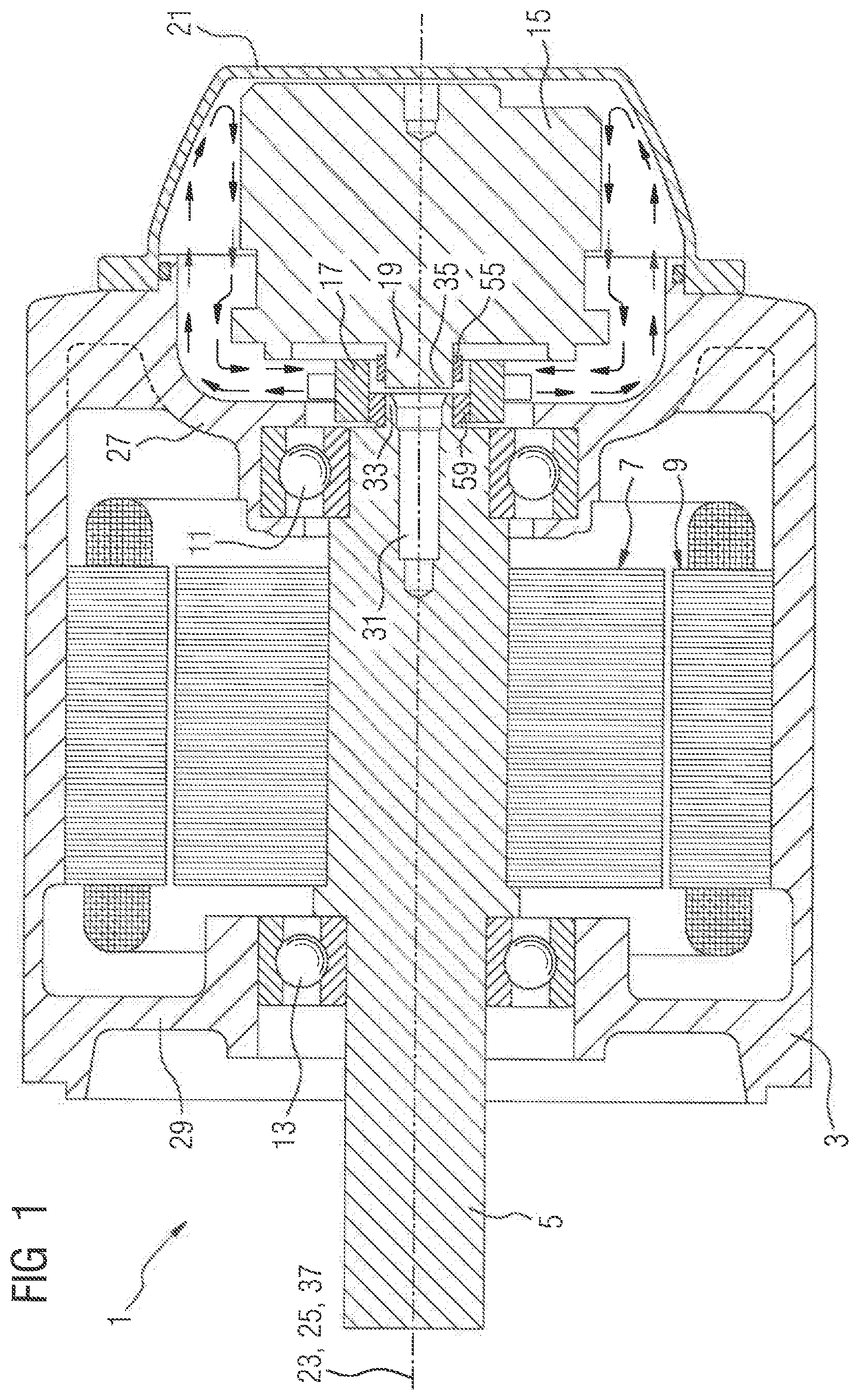
[0022] FIG. 1 shows a sectional view of a motor having a rotary encoder,
[0023] FIG. 2 shows an enlarged detail of FIG. 1,
[0024] FIG. 3 shows a perspective sectional view of the motor shown in FIG. 1 in the region of the rotary encoder, and
[0025] FIG. 4 shows a perspective view of a connecting element for connecting a motor shaft of a motor to an encoder shaft of a rotary encoder.
[0026] Parts corresponding to one another are labeled with the same reference numerals in all the figures.
[0027] FIG. 1 shows a schematic sectional view of a motor 1, which is an electric motor. The motor 1 comprises a motor housing 3, a motor shaft 5, a rotor 7 arranged on the motor shaft 5, a stator 9 arranged around the rotor 7 on the motor housing 3, two motor shaft bearings 11, 13 for mounting the motor shaft 5, a rotary encoder 15 for detecting a rotational position and/or a rotational speed of the motor shaft 5, a connecting element 17 for connecting the motor shaft 5 to an encoder shaft 19 of the rotary encoder 15, and an encoder cover 21.
[0028] FIG. 2 shows an enlarged detail of FIG. 1 in the region of the connecting element 17.
[0029] FIG. 3 shows a perspective sectional view of the motor 1 illustrated in FIG. 1 in the region of the rotary encoder 15.
[0030] FIG. 4 shows a perspective view of the connecting element 17.
[0031] The motor shaft 5 is mounted by means of the motor shaft bearings 11, 13 so as to be rotatable about a motor shaft longitudinal axis 23 of the motor shaft 5. A first motor shaft bearing 11 is arranged on a first bearing shield 27 of the motor housing 3 facing toward the rotary encoder 15. The second motor shaft bearing 13 is arranged on a second bearing shield 29 of the motor housing 3 facing away from the rotary encoder 15. On the rotary encoder side, the motor shaft 5 has a bore 31 extending along the motor shaft longitudinal axis 23.
[0032] The rotary encoder 15 is mounted so as to be rotatable about an encoder shaft longitudinal axis 25 which coincides with the motor shaft longitudinal axis 23.
[0033] The encoder cover 21 is embodied in a pot-like shape and seals off an end of the motor housing 3 on the rotary encoder side. The encoder cover 21 protects the rotary encoder 15 against influences from the environment of the motor 1.
[0034] The connecting element 17 connects a motor shaft end 33 of the motor shaft 5 on the encoder shaft side to an encoder shaft end 35 of the encoder shaft 19 on the motor shaft side, such that the encoder shaft 19 co-rotates with the motor shaft 5. The motor shaft end 33 and the encoder shaft end 35 have at least approximately equal outer diameters and are spaced apart from one another.
[0035] The connecting element 17 comprises a connecting region 39 which runs in an annular shape around a connecting axis 37, as well as a plurality of fan blades 41. The connecting axis 37 coincides with the motor shaft longitudinal axis 23 and the encoder shaft longitudinal axis 25. The connecting region 39 has two end sides 43, 45 which lie axially opposite one another, an outer side 47 facing away from the connecting axis 37, and an inner side 49 facing toward the connecting axis 37. A first end side 43 of the connecting region 39 faces toward the motor shaft 5, while the second end side 45 faces toward the rotary encoder 15. The fan blades 41 protrude radially from the outer side 47 of the connecting region 39. The terms radially and axially refer in this context to the connecting axis 37.
[0036] The fan blades 41 are distributed at regular intervals along a circle around the connecting axis 47 on the outer side 47 of the connecting region 39. In the exemplary embodiment illustrated in FIG. 4, the connecting element 17 has four fan blades 41. However, alternative exemplary embodiments of the connecting element 17 may also have a different number of fan blades 41. Each fan blade 41 has substantially the shape of a prism with a triangular base area which stands out vertically from the outer side 47 of the connecting region 39. During a rotation of the motor shaft 5, the fan blades 41 generate an air flow, indicated by arrows in FIG. 1, which distributes colder air from the region of the encoder cover 21 around the rotary encoder 15 and thereby advantageously cools the rotary encoder 15.
[0037] Each end side 43, 45 of the connecting region 39 of the connecting element 17 has two coupling recesses 51 which extend radially in each case from the inner side 49 to the outer side 47 of the connecting region 39 and are disposed radially opposite one another. The coupling recesses 51 of the first end side 43 are offset by 90 degrees relative to the coupling recesses 51 of the second end side 45. Each coupling recess 51 has an axial depth which is roughly half as great as the axial extension of the connecting region 39.
[0038] For each coupling recess 51 of the second end side 45 of the connecting region 39, the encoder shaft end 35 has an encoder shaft stud 53 projecting radially into the coupling recess 51. Each encoder shaft stud 53 is part of an encoder shaft attachment 55 which annularly surrounds the encoder shaft end 35 and is press-fitted onto the encoder shaft end 35. The engagement of the encoder shaft studs 53 into the coupling recesses 51 of the second end side 45 of the connecting region 39 causes the encoder shaft end 35 to be connected to the connecting element 17 in a positive-locking manner.
[0039] Analogously thereto, for each coupling recess 51 of the first end side 43 of the connecting region 39, the motor shaft end 33 has a motor shaft stud 57 projecting radially into the coupling recess 51. Each motor shaft stud 57 is part of a motor shaft attachment 59 which annularly surrounds the motor shaft end 33 and is press-fitted onto the motor shaft end 33. The engagement of the motor shaft studs 57 into the coupling recesses 51 of the first end side 43 of the connecting region 39 causes the motor shaft end 33 to be connected to the connecting element 17 in a positive-locking manner.
[0040] The positive-locking connections of the motor shaft end 33 and the encoder shaft end 35 to the connecting element 17 enable axial displacements of the motor shaft end 33 and the encoder shaft end 35 relative to the connecting element 17, such that temperature-induced changes in length of the motor shaft 5 and the encoder shaft 19 can be compensated for by the connecting element 17.
[0041] In order to facilitate such axial displacements of the motor shaft end 33 and the encoder shaft end 35 relative to the connecting element 17, the connecting element 17 has axially extending groove-like indentations 61 in each wall bounding a coupling recess 51 and starting from an end side 43, 45 of the connecting region 39. The friction between the connecting element 17 and the motor shaft end 33 and the encoder shaft end 35 is advantageously reduced by the indentations 61 as a result of a reduction in the size of the friction surfaces between the connecting element 17 and the motor shaft end 33 and the encoder shaft end 35. Furthermore, the indentations 61 can accommodate a lubricant which is used for lubricating the coupling recesses 51, thereby further reducing the friction between the connecting element 17 and the motor shaft end 33 and the encoder shaft end 35.
[0042] Optionally, the connecting region 39 has a plurality of cutouts 63 which extend axially in each case from an end side 43, 45 and spaced apart from the outer side 47 and from the inner side 49. This advantageously enables the mass of the connecting element 17 to be reduced.
[0043] The connecting element 17 is preferably fabricated from a plastic material and formed as a single, integral unit, and produced in an injection molding process, for example.
[0044] Although the invention has been illustrated and described in more detail on the basis of preferred exemplary embodiments, the invention is not limited by the disclosed examples and other variations may be derived herefrom by the person skilled in the art without leaving the scope of protection of the invention.
* * * * *
D00000
D00001
D00002
D00003
D00004
XML
uspto.report is an independent third-party trademark research tool that is not affiliated, endorsed, or sponsored by the United States Patent and Trademark Office (USPTO) or any other governmental organization. The information provided by uspto.report is based on publicly available data at the time of writing and is intended for informational purposes only.
While we strive to provide accurate and up-to-date information, we do not guarantee the accuracy, completeness, reliability, or suitability of the information displayed on this site. The use of this site is at your own risk. Any reliance you place on such information is therefore strictly at your own risk.
All official trademark data, including owner information, should be verified by visiting the official USPTO website at www.uspto.gov. This site is not intended to replace professional legal advice and should not be used as a substitute for consulting with a legal professional who is knowledgeable about trademark law.